4 — U2G460 Quick Start Guide
GAttach all of the connectors to the brackets on the
rails and chassis. There should be one at the
elbow side and two at the other end.
Lower CMA orientation
HSlowly slide the enclosure forward to ensure the
CMA arm is operating properly, then slide it back
into the rack.
IMirror the steps above to install the lower cable
management arm.
Step 4: Thread the cables through the
CMAs
NOTE: Before cabling the CMAs, note the following
routing of the cables. For best results, the cables
that are supported by the upper CMA are inserted
into IOM B (right hand side looking at the rear) and
the lower CMA cables are routed to IOM A (left hand
side looking at the rear)
Thread the cables into the CMAs, beginning with the
lower CMA.
AUnlatch the elbow side of the CMA arm and swing
it forward by pressing the blue button that says
“push” to unlatch it.
BGather the SAS cables, one power cable, and one
Ethernet cable to install in the left hand side.
For each cable, reserve enough slack at the
connector end to operate smoothly. Allow 20" -
21" (508 – 533.4mm) between the end of the
connector and the first basket. Make sure to route
all of the upper CMA cables under the lower CMA
cables.
CTest for binding in the extension of the CMAs by
gently pulling the enclosure out of the rack to
ensure the cables extend properly and that the
system doesn’t bind. Adjust the lengths as
necessary.
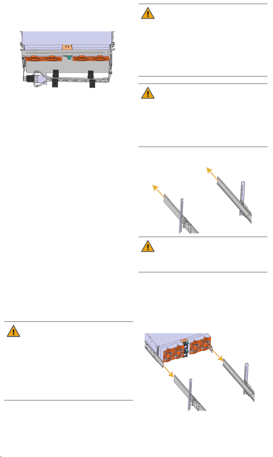
Step 5: Install the U2G460 on the rack
AExtend the mid-rails out of the rack so that they
are protruding from the front of the rack and the
safety latches engage.
BTeam lift the U2G460 chassis from the sides—not
from the front and back.
CLine up the inner-chassis rails with the extended
rack rails, until the rail locks engage.
DLocate the blue tabs on each of the inner rails,
and slide them towards the front of the chassis.
Push on the chassis, pushing the U2G460
completely into the rack; you should hear the
locking tabs click into position.
ETighten the thumbscrews that hold the front of the
U2G460 to the rack.
CAUTION: This step in the installation
requires a minimum of 3 individuals to
install safely, two to lift and one to guide
the others whom may have difficulty seeing
because the enclosure is in the way.
Ensure that the appropriate measures are
taken to safely support the enclosure
during installation. The enclosure MUST
have no drives installed and requires a two
person team lift to install. Do not attempt to
lift the system if it is fully populated with
drives.
CAUTION: The handles on the front of the
chassis are not intended to be used to
support the weight of the Ultrastar Data60.
Lifting the unit by the chassis handles or
trying to support the unit on the handles
can cause them to fail. This can cause
serious damage to the unit or serious
bodily harm to those handling the unit.
Always team lift the chassis by gripping the
underside of the unit, and never try to lift a
chassis that is filled with drives.
WARNING: Do not lift the chassis by the
cable tray while removing the chassis from
the rack OR while installing it into a rack.
This can cause serious damage to the
storage expansion or serious bodily harm
to those handling it.
Always team lift the chassis by gripping the
underside of the unit, and never try to lift a
chassis that is filled with drives.
CAUTION: To prevent potential damage
due to improper mating of the rails, make
sure that the bearing plates on the inside of
the mid-rails are fully forward and that the
lock has engaged.


