Part number: P0450170 Rev: E Release Date: August 2019
Related Documentation: Nexsan Unity Hardware Maintenance Guide,
Nexsan Unity User Guide, Nexsan Unity Online Help, Nexsan Unity
nxadmin CLI Reference Guide
Technical Support
By Web: http://helper.nexsansupport.com/unt_support.html
Nexsan 325 E. Hillcrest Drive, Suite 150, Thousand Oaks, CA 91360 | www.nexsan.com
Copyright © 2010-2019 Nexsan Technologies, Inc. All Rights Reserved. Nexsan®, UNITY2200™, UNITY4400™, UNITY6900™, UNITY2200X™, US224™,
US316™, US424™, US460,™, FASTier™, and the Nexsan logo are trademarks or registered trademarks of Nexsan . All other trademarks and registered
trademarks are the property of their respective owners.
If the Fan fail LED or Power fail LED illuminates,
replace the component as described in the Nexsan
Unity Storage Expansion Reference Guide.
Drive carrier LEDs
Each drive carrier on the US316 Expansion has two
LEDs. If a drive fails, replace the drive as described
in the Nexsan Unity Storage Expansion Reference
Guide at www.nexsan.com/ (see Support > Unity >
DocumentaUS424US424tion & Online Help).
.
Safety notices
This equipment must be installed and operated in
compliance with local laws and regulations.
Ensure that the ambient temperature at the
installation site is between 5°C (41°F) and 30°C
(86°F). If the temperature at the site is not actively
regulated, ensure that daily and seasonal
temperature changes will not result in the ambient
temperature going outside these limits.
Always fully stabilize racks with wall anchors or
stabilizing legs, or both, before mounting the
Nexsan storage enclosure or any other
components on the rack.
Situate the rack so that full air flow at both the
front and the rear of the Nexsan storage enclosure
is possible.
Ensure that the floor beneath the mounting rack
has enough load-bearing capacity to support the
rack and all mounted components.
Always fully secure all rack-mounting hardware
when installing the Nexsan storage enclosure in a
rack. Insufficient rack-mount support may allow
the enclosure to fall onto other rack-mounted
hardware or onto the floor, potentially damaging
equipment or causing injury.
Rack and enclosure specifications
Rail kit mounting
3U enclosure height
The rack has square holes
Maximum distances: 30" (800 mm)
Enclosure dimensions
Height: 5.25’’/133 mm
Width: 17.25’/’438 mm
Depth: 26.25’’/667 mm
Weight
54 lbs/24.5 kg (no drives installed)
75 lbs/34 kg (all drives installed)
Power requirements
Power supply: 1200W
Input voltage: 100-240V
Amperage: 12V (100A @ 240V), +5Vsb (6A @
240V, 4A @ 100V)
Input frequency: 50/60 Hz
Power consumption: Varies, depending on the
number and size of drives, running fans, and room
temperature
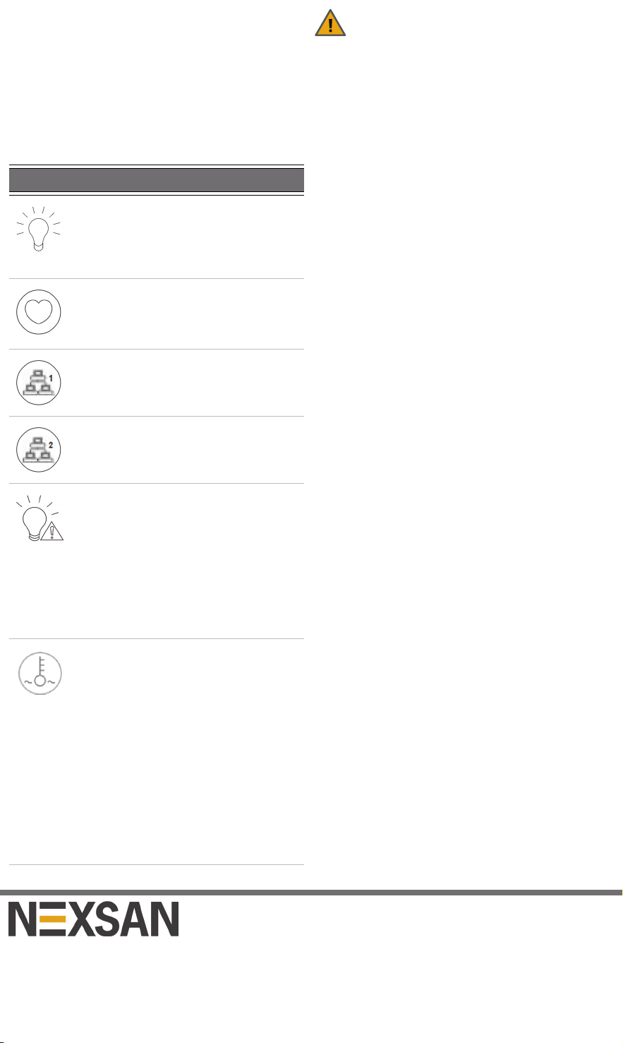
LED Indication
Power
Indicates power is being supplied to
the system’s power supply units. This
LED is illuminated when the system is
operating.
Heartbeat
This is a server board heartbeat LED
and indicates that power is being
supplied to the server board.
NIC1
Indicates network activity on the LAN1
port when flashing.
NIC2
Indicates network activity on the LAN2
port when flashing.
Power fail
Indicates a power supply module has
failed. The second power supply
module takes the load and keeps the
system running, but the failed module
should be replaced as soon as
possible.
This LED should be off when the
system is operating normally.
Fan fail
When flashing, this LED indicates a
fan failure.
When lit continuously, this LED
indicates an overheated condition,
which may be caused by cables
obstructing the airflow in the system or
the room temperature being too high.
Check the routing of the cables and
make sure that all fans are connected
and operating normally. You should
also check to make sure that the
chassis covers are installed.