Copyright © 2010-2016 Nexsan Corporation. All Rights Reserved. Nexsan®, E-Centre™, UNITY4000™, UNITY6000™, UNITY6000MC™, UNITY224X™,
E18™, E48™, E60™, FASTier™, and the Nexsan logo are trademarks or registered trademarks of Nexsan Corporation. All other trademarks and
registered trademarks are the property of their respective owners.
Nexsan 900 E Hamilton Ave, Suite 230, Campbell, CA 95008 | p. 1.866.463.9726 | www.nexsan.com
Part number: P0450158 Rev: ARelease Date: June 2016
Related Documentation: Nexsan UNITY Hardware Reference Guide,
Nexsan UNITY Software User Guide, Nexsan UNITY nxadmin CLI
Reference Guide
Technical Support
By Phone:
U.S. & Canada: +1 (866) 263-9726
Global: U.S. Toll +1 (760) 690-1111
By Web: http://helper.nexsansupport.com/nexsan_aaq.html
Attach the front bezel
If all LEDs indicate normal operational status, attach
the front bezel to the UNITY224X:
AUnpack the front bezel of the expansion unit from
its packaging.
BHook the left end of the bezel onto the chassis.
CFit the right side of the bezel onto the chassis.
DTurn the key lock at the right end of the bezel to
the lock position to secure the bezel to the chassis.
Monitor the UNITY224X
To monitor the enclosure:
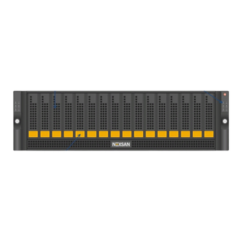
Four LEDs on the right side of the front of the
UNITY224X Expander’s enclosure indicate the
status of the whole enclosure.
When a failure occurs on a
controller or PSU unit, the
enclosure LEDs indicate an
enclosure fault.
For instructions to replace a
controller or a PSU unit,
see the Nexsan UNITY
Expander Unit Reference
Guide.
To monitor the disk drives:
Each disk drive carrier has three LEDs that indicate
the status of the disk drive. For instructions to
replace a disk drive, see the Nexsan UNITY
Expander Unit Reference Guide.
Safety Notices
This equipment must be installed and operated in
compliance with local laws and regulations.
Ensure that the ambient temperature at the
installation is between 5°C (41°F) and 30°C
(86°F). If the temperature at the site is not actively
regulated, ensure that daily and seasonal
temperature changes will not result in the ambient
temperature going outside these limits.
Always fully stabilize racks with wall anchors or
stabilizing legs, or both, before mounting the
Nexsan storage unit or any other components on
the rack.
Situate the rack so that full air flow at both the
front and the rear of the Nexsan storage unit is
possible.
Ensure that the floor beneath the mounting rack
has enough load-bearing capacity to support the
rack and all mounted components.
Always fully secure all rack-mounting hardware
when installing the Nexsan storage unit in a rack.
Insufficient rack-mount support may allow the unit
to fall onto other rack-mounted hardware or onto
the floor, potentially damaging equipment or
causing injury to nearby personnel.
Rack and Enclosure Specifications
Rail Kit Mounting
2U enclosure height
The rack has square roles
Maximum distances: 30" (800 mm)
Enclosure Dimensions
Height: 3.5’’ 88 mm
Width: 17.6’’ 447 mm
Depth: 19.3’’ 490 mm
Weight
Weight: 53 lbs 27 kg (all drives installed)
Power Requirements
Power supply: 920W
Input voltage: 100-240V
Amperage: 5V @ 45A, 3.3V @ 24A, -12V @0.6A
Input frequency: 50/60 Hz
Power consumption: varies depending on the
number and size of drives, running fans, and
room temperature
LED Condition Color Indication
1 N/A White Not used
2 On Amber Enclosure fault
3 Flash Amber Service action
allowed
4 On Green Power on
LED Condition Color Indication
Blue On Blue Service
action
allowed
(not used)
Yellow On Amber Drive
fault
Green On/
Flashing Green Drive
ready


