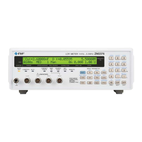
NF ZM2376 User manual

LCR METER
ZM2376
Instruction Manual
(Alternative Commands)
NF Corporation


LCR METER
ZM2376
Instruction Manual
(Alternative Commands)
DA00042210-001


Preface
This instruction manual describes the alternative commands of ZM2376.
The following instruction manuals are provided for ZM2376.
ZM2376 Instruction Manual (Basics)
This manual describes basic items such as how to operate ZM2376 from the panel,
specifications, and maintenance.
ZM2376 Instruction Manual (Remote Control)
This manual describes the remote control of ZM2376.
It includes the description of standard commands.
Standard commands are used in the operation mode 0 (initial value).
ZM2376 Instruction Manual (Alternative Commands)
This manual describes the alternative commands of ZM2376.
Alternative commands are used in the operation mode 1.
If you find the alternative commands easier to use than the standard commands, use them.
However, the alternative commands provides limited functions.
“ZM2376 Instruction Manual (Remote Control)” and “ZM2376 Instruction Manual (Alternative
Commands)” are included in the attached CD-ROM.
This instruction manual has the following chapters.
1. PREPARATIONS BEFORE USE
Describes the setting and precautions of the interfaces.
2. RESPONSE TO INTERFACE MESSAGE
Lists the responses to main IEEE-488.1 interface messages.
3. ALTERNATIVE COMMAND LIST AND COMMAND TREE
Describes the overview of all the alternative commands.
4. ALTERNATIVE COMMAND EXPLANATION
Describes the details of individual alternative commands.
5. STATUS SYSTEM
Describes the status system in the operation mode 1.
6. TRIGGER SYSTEM
Describes the overview of the trigger system and the measurement procedure of the remote control.
7. ERROR MESSAGE
Describes the error messages of the remote control.
iZM2376

Table of Contents
Page
1. PREPARATIONS BEFORE USE············································································ 1
1.1 Outline of Operation Mode 1.................................................................................................1
1.2 Switching of Operation Mode................................................................................................1
1.3 Initial Value (Operation Mode 1)...........................................................................................2
2. RESPONSE TO INTERFACE MESSAGE································································· 3
3. ALTERNATIVE COMMAND LIST AND COMMAND TREE··········································· 4
4. ALTERNATIVE COMMAND EXPLANATION····························································· 8
4.1 Outline of Command Language............................................................................................8
4.1.1 Subsystem Commands ......................................................................................................................8
4.1.2 Path Separator....................................................................................................................................8
4.1.3 Keywords Simplification.....................................................................................................................9
4.2 Overlap Commands and Sequential Commands..............................................................9
4.3 Alternative Command Details..............................................................................................10
4.3.1 Common Commands........................................................................................................................11
4.3.2 Alternative Subsystem Commands.................................................................................................15
5. STATUS SYSTEM······························································································26
5.1 Outline of Status System .....................................................................................................26
5.2 Status Byte ............................................................................................................................27
5.3 Standard Event Status .........................................................................................................29
5.4 Extension event status.........................................................................................................31
6. TRIGGER SYSTEM····························································································33
7. Error Messages ·································································································35
Attached Figures and Tables
Page
Figure 5-1 Status system ······················································································26
Figure 5-2 Standard event status structure ·······························································29
Figure 5-3 Extension event status structure ······························································31
Figure 6-1 Trigger system ·····················································································33
Table 1-1 Initial value (specific to operation mode 1) ··················································· 2
Table 2-1 Responses to interface messages (operation mode 1)···································· 3
Table 3-1 Common command list (operation mode 1) ·················································· 4
Table 3-2 Subsystem command list (operation mode 1)················································ 5
Table 5-1 Status byte register definitions··································································27
Table 5-2 Standard event status register contents······················································29
Table 5-3 Event status register 0 contents································································32
Table 5-4 Event status register 1 contents································································32
ii ZM2376

1.PREPARATIONS BEFORE USE
1.PREPARATIONS BEFORE USE
1.1 Outline of Operation Mode 1
In ZM2376, you can switch the operation mode to use the alternative command instead of the
standard command. Use the operation mode 1 when the alternative command is easier to use for you.
However, the alternative command does not support all of the functions in ZM2376.
Operation mode 1 also provides the same operation from the panel. However, if you operate a
function unsupported by the alternative command from the panel, unintended operation may be
caused. It is recommended that you only use functions that are available from the initial settings with
the alternative command in the operation mode 1.
1.2 Switching of operation mode
The initial value of the operation mode is 0 (standard command mode).
To use the alternative command, switch the operation mode of ZM2376 to 1 (alternative command
mode). The operation mode is not initialized by the power on/off and the full initialization by the
_SHIFT_+ [INIT] key operation or from the system setting menu.
_SHIFT_+ [ SYSTEM ]
Press the _SHIFT_+ [SYSTEM] keys to display the system setting menu.
SYSTEM settings
0)INTERFACE 1)BEEPER >NEXT Options (first page)
Press the _-__2__3__0__0_keys in this order to display the operation mode setting menu as
shown below. (This option is not displayed in the system menu.)
Operation mode:0 Current setting
0)Mode 0 1)Mode 1 Options
Press the _1_key to enter the operation mode 1.
When the operation mode is set, the initialization equivalent to “INITIALIZE ALL” in each
operation mode is executed.
In the operation mode 1, the underline cursor is displayed at the end of second line of the display.
Operation mode 0 • • • • • • • 1.00000k
• • • • • • • 1.00 V
Operation mode 1 • • • • • • • 1.00000k
• • • • • • • 1.00 VUnderline
1ZM2376

1.PREPARATIONS BEFORE USE
1.3 Initial Value (Operation Mode1)
Initial values specific to the operation mode 1 are as follows. The other initial values are the same as
the operation mode 0.
Table 1-1 Initial value (specific to operation mode 1)
Setting item Parameter range Initial value INIT *RST
Setting
memory
Resume
:MEASure? response
parameter
5, 0 (equivalent
to Z, θ)
←←
GPIB response terminator
{LF+EOI | CR,LF+EOI}
0
×
×
×
The GPIB response terminator is initialized by operating the full initialization in the system setting
menu or switching the operation mode.
Remarks
Initial value Set when full initialization is executed with the system setting menu.
INIT Set when initialization is executed with the initialize menu ( SHIFT + [INIT]).
*RST Set when *RST command of remote control is executed
←Same as left (initial values)
× Function not provided. (No influence)
Function provided.
Function provided. However, it is saved independently from general resume
target ().
2ZM2376

2.RESPONSE TO INTERFACE MESSAGE
2.RESPONSE TO INTERFACE MESSAGE
The responses to main IEEE-488.1 interface messages are as listed below.
Table 2-1 Responses to interface messages (operation mode 1)
Message Function
IFC < InterFace Clear >
Initializes the GPIB interface.
Releases the specified listener and talker.
DCL,SDC < Device CLear >, < Selected Device Clear >
Clears the input buffer and stops interpretation and execution of a command.
Clears the output buffer and clears the bit 4 (MAV) of status byte register.
Releases the overlap command queuing by *WAI, *OPC, and *OPC? commands.
LLO < Local LockOut >
Disables the transition from remote state to local state by pressing the _LOCAL_key on
the panel.
GTL < Go To Local >
Selects the local state.
GET < Group Execute Trigger >
Executes the trigger. Same function as *TRG command.
How to send an interface message from the controller is different depending on the device driver. For
details, see the manual of each driver.
3ZM2376

3.ALTERNATIVE COMMAND LIST AND COMMAND TREE
3.ALTERNATIVE COMMAND LIST AND COMMAND TREE
ZM2376 alternative commands are separated into the common commands defined by IEEE488.2 and
subsystem commands which reflect instrument-specific functions.
The common commands and subsystem commands provided by ZM2376 are listed below.
The meanings of symbols used in the list are as follows:
• Keywords shown in square brackets ([ ]) are omissible. (Implicit Keywords)
• The vertical bar ( | ) indicates the possibility to select a keyword from several keywords.
• It is possible to omit the lowercase part of each keyword.
Table 3-1 Common command list (operation mode1)
Command
Name
Function
*CLS
Clear Staus Command
Clears status data.
*ESE
*ESE?
Standard Event Status
Enable Command /
Query
Sets/queries the standard event status enable
register.
*ESR?
Standard Event Status
Register Query
Queries the standard event status register contents.
*IDN?
Identification Query
Queries the device identification information (model
name etc).
*OPC
*OPC?
Operation Complete
Command / Query
Requests to set the Standard Event Status register’s
OPC bit to 1 when all command operations are
completed. In response to query, it returns 1 when all
operations are completed.
*RST
Reset Command
Resets the instrument to restore the initial setting
values.
*SRE
*SRE?
Service Request Enable
Command / Query
Sets/queries the service request enable register.
*STB?
Read Status Byte Query
Queries the status byte.
*TRG
Trigger Command
Applies the trigger to perform measurement once,
when the instrument waits for trigger.
*TST?
Self-Test Query
Queries the self-diagnosis result.
“0” (no error) is returned, if normal.
*WAI
Wait-to-Continue
Command
Waits for executing the following commands until all of
the preceding command operations are completed.
4ZM2376

3.ALTERNATIVE COMMAND LIST AND COMMAND TREE
Table 3-2 Subsystem command list (operation mode1)
1/2
Command
Function / Operation target
:APPLication:DISPlay:LIGHt
(Backlight on/off. Always on)
:APPLication:DISPlay:MONItor
Displays voltage/current monitored value
:AVERaging
Averaging count
:BEEPer:COMParator
Enables beeper of comparator
:BEEPer:KEY
(Enables beeper of key entry. Always off)
:CABLe
Cable length correction
:COMParator
Enables limit comparison
:COMParator:FLIMit:ABSolute
Upper and lower limit values of primary parameter
:COMParator:FLIMit:DEViation
Reference value and upper and lower limit values of
primary parameter
:COMParator:FLIMit:MODE
Limit comparison mode of primary parameter
:COMParator:FLIMit:PERcent
= :COMParator:FLIMit:DEViation
:COMParator:SLIMit:ABSolute
Upper and lower limit values of secondary parameter
:COMParator:SLIMit:DEViation
Reference value and upper and lower limit values of
secondary parameter
:COMParator:SLIMit:MODE
Limit comparison mode of secondary parameter
:COMParator:SLIMit:PERcent
= :COMParator:SLIMit:DEViation
:CORRection:DATA?
Queries spot correction value
:CORRection:OPEN
OPEN correction
:CORRection:SHORt
SHORT correction
:DISPlay:MONItor?
Queries voltage/current monitored value
:ERRor?
(Queries RS-232 error. Always returns 0)
:ESE0
Event status enable register 0
:ESR0?
Queries event status register 0
:ESR1?
Queries event status register 1
:FREQuency
Measurement frequency
:IO:OUTPut:DELay
(/EOM delay time. Fixed)
:LEVel
Signal level mode
:LEVel:CCURRent
Constant current level
:LEVel:CVOLTage
Constant voltage level
:LEVel:VOLTage
Open voltage
:LIMiter
(Enables signal level limit. Always off)
:LIMiter:CURRent
(Signal current limiting value. Always maximum value)
:LIMiter:VOLTage
(Signal voltage limiting value. Always maximum value)
:LOAD
Recalls settings and correction value
:MEASure?
Reads measured value
:MEASure:ITEM
Specifies measured value to be read
5ZM2376

3.ALTERNATIVE COMMAND LIST AND COMMAND TREE
Table 3-2 Subsystem command list (operation mode 1)
2/2
Command
Function / Operation target
:PARameter1
Primary parameter and its equivalent circuit
:PARameter2
(Nothing is set)
:PARameter3
Secondary parameter and its equivalent circuit
:PARameter4
(Nothing is set)
:PARameter:DIGit
(Number of measured value display digits. Always auto)
:RANGe / :RANGe?
Sets/queries measurement range
:RANGe:AUTO
Enables automatic selection of measurement range
:SAVE
Saves settings and correction value
:SPEEd
Measurement speed
:TRANsmit:TERMinator
GPIB response message terminator
:TRIGger
Trigger mode
:TRIGger:DELAy
Trigger delay time
:USER:IDENtity
(Fixed. Nothing is changed even if set)
Supplement: A command that makes inquiry is called “query” and it ends with a question mark.
The operation mode 1 (alternative command mode) does not support most queries.
Queries not described in this table or detailed explanation below cannot be used.
6ZM2376

3.ALTERNATIVE COMMAND LIST AND COMMAND TREE
The subsystem command tree of ZM2376 is shown below.
Command tree (operation mode 1)
<Root>
:APPLication :DISPlay :LIGHt
:MONItor
:AVERaging
:BEEPer :COMParator
:KEY
:CABLe
:COMParator
:FLIMit :ABSolute
:DEViation
:MODE
:PERcent
:SLIMit :ABSolute
:DEViation
:MODE
:PERcent
:CORRection :DATA?
:OPEN
:SHORt
:DISPlay :MONItor?
:ERRor?
:ESE0
:ESR0?
:ESR1?
:FREQuency
:IO :OUTPut :DELay
:LEVel
:CCURRent
:CVOLTage
:VOLTage
:LIMiter
:CURRent
:VOLTage
:LOAD
:MEASure?
:MEASure :ITEM
:PARameter :DIGit
:PARameter1
:PARameter2
:PARameter3
:PARameter4
:RANGe?
:RANGe
:AUTO
:SAVE
:SPEEd
:TRANsmit :TERMinator
:TRIGger
:DELAy
:USER :IDENtity
7ZM2376

4.ALTERNATIVE COMMAND EXPLANATION
4.ALTERNATIVE COMMAND EXPLANATION
4.1 Outline of Command Language
4.1.1 Subsystem Commands
Commands are divided into groups depending on their function. Subsystem commands are arranged
in a hierarchy. The colon ( : ) is defined as the path separator.
4.1.2 Path Separator
The path separator ( : ) separates the current keyword from the keywords one level lower. In a
command character string, each colon ( : ) indicates a displacement to the path one level below the
current path.
When the colon ( : ) is found at the beginning of a command character string it means “to set the
current path to root”. The current path is also set to root by the power on, *RST command, or
message terminator. The beginning of a program message is always set to root. A colon ( : ) at the
beginning of a command character string is omissible arbitrarily.
:LEV:VOLT 1
Set current path to root (Omissible)
LEVel subsystem command (LEVel is a root command)
LEVel subsystem attached VOLTage command
A space is required between the header and the parameters
By separating the commands with a semicolon ( ; ), plural command character strings can be put
together into one program message.
:COMP:FLIM:DEV 2.2E-6, -3, +3 ; :COMP:FLIM:MODE PER
Command 1 Command 2
The above example shows one program message equivalent to the following two program
messages.
:COMP:FLIM:DEV 2.2E-6, -3, +3 Current path after execution is :COMP:FLIM:
:COMP:FLIM:MODE PER
If a colon ( :) is omitted in the second and subsequent command character strings, the
subsystem command on the same level is accessible without changing the current path.
:COMP:FLIM:DEV 2.2E-6, -3, +3 ; MODE PER In the second command string,
:COMP:FLIM: is omissible
In both cases, the program message terminator at the end is omitted.
↑
↑
↑
↑
8ZM2376

4.ALTERNATIVE COMMAND EXPLANATION
4.1.3 Keywords Simplification
In this Instruction Manual, a keyword indicating a command or parameter is expressed with a
combination of uppercase and lowercase alphabets. Uppercase characters are used for short form
(abbreviation). Even if lowercase character part is all omitted, it has the same function as long form
that includes all the lowercase character part. However, only a part of lowercase character part cannot
be omitted.
Uppercase and lowercase characters are used only as an expedient means to explicit the form that can
be shortened but instrument makes no distinction whatsoever between the two. It is possible to use
both simultaneously.
Ex.) Command notation :DISPlay:MONItor? (Acceptable, × Error)
→:display:monitor? Long form, all lowercase character
:Disp:Moni? Short form, mixed uppercase/lowercase characters
:DISPL:MONI? × Wrong intermediary abbreviated form
:DISP:MON?× Omission over-abbreviated
4.2 Overlap Commands and Sequential Commands
Some commands allow the following commands to be executed simultaneously during execution of
them, and some commands do not allow.
Overlap commands
During execution of that command, the following command can be executed.
Sequential commands
After execution of that command finished, the following command is executed.
Note that executing multiple overlap commands will result in an operation failure.
Use *WAI, *OPC, and *OPC? commands when you do not want to execute the following commands
or query until the execution of overlap commands finished.
The commands given below are overlap commands. Other commands are all sequential commands.
Overlap commands :
:CORRection:OPEN
:CORRection:SHORt
9ZM2376

4.ALTERNATIVE COMMAND EXPLANATION
4.3 Alternative Command Details
The function and syntax of each command shown in “Table 3-1 Common command list
(alternative command)” and “Table 3-2 Subsystem command list (alternative command)” are
explained below.
[Meaning of symbols]
• Keywords shown in square brackets ([ ]) are omissible.(Implicit Keywords)
• Curly braces ({ }) indicate parameters in the command character string.
• The vertical bar (|) indicates possibilities to select a keyword from several options.
• Comparison marks (< >) indicate that a parameter such as numerical values and
character strings need to be set.
These symbols are used for description only. They are not used in actual commands.
Description [:ABCDe][:FGHijk]:COMMandx {ON|OFF}
Actual command :ABCDe:FGHijk:COMMandx ON
[Parameters data format]
Symbol
Format
ex.
NR1
Integer (numeric value)
123
NR2
Decimal point format no having exponent (numeric
value)
0.075
NR3
Decimal point format having exponent (numeric
value)
4.99E+06
CRD
Character strings
ALL
SRD
Character strings in double quotation marks
"No error"
bool
Logical value
ON, OFF, 1, 0
• Unless otherwise specified individually, a numeric value in any format is accepted and it
is rounded to the nearest value if exceeding the specified resolution.
• Unless otherwise specified individually, a numeric value is set to minimum value if
below the minimum value, or set to maximum value if above the maximum value.
• For numeric value parameters in which the description is made so that MAX / MIN can
be used, a numeric value is set to maximum value if MAX (or MAXIMUM) is given, or
set to minimum value if MIN (or MINIMUM) is given.
• When the response is a numeric value, and the range, resolution and unit are omitted, it
is same as a setting. Unless otherwise specified individually, the mantissa of response in
NR3 format is 6 digits.
• For the commands in which the parameter type varies depending on the format setting,
even if a numeric value exceeding the range mentioned below is given, it is rounded to
the same range as displayed on panel or resolution. For the range of actually set value,
see the description of operation panel.
• Character strings in quotation marks are accepted in single or double quotation marks.
[Remarks]
• Both commands and queries are called commands here.
The keyword attached with “?” at the end is a query.
• Response messages to commands do not come with headers. They cannot have headers.
10 ZM2376

4.ALTERNATIVE COMMAND EXPLANATION
4.3.1 Common Commands
*CLS
Description: Clears the following statuses.
• Standard event status register
• Extension event status register
• Status Byte
• Error queue
Also, the error display on the panel is reset.
Setting example: *CLS
Remarks: The *CLS command does not directly clears the status byte register. Except for
the MAV bit and the RQS bit, the status byte is indirectly cleared. It is possible
to indirectly clear the MAV bit by clearing the input buffer with a device clear. It
is possible to clear the RQS bit by reading out the status with the serial pole.
*ESE <mask>
*ESE?
Description: Sets/Queries the standard event status enable register.
Parameter: <mask> {numeric value, range 0 to 255} Out of range value causes an error.
Details • • • "5.3 Standard Event Status"
Setting example: *ESE 255
Sets 255 to the standard event status enable register.
Response: <mask> {numeric value, format NR1, range 0 to 255}
Query example: *ESE?
Response example: +255
The content of standard event status enable register is 255.
*ESR?
Description: Queries the standard event status register contents.
The query clears all the standard event status register bits to 0.
Response: <register contents> {numeric value, format NR1, range 0 to 255}
Details • • • "5.3 Standard Event Status"
Query example: *ESR?
Response example: +128
The content of standard event status register is 128.
11 ZM2376

4.ALTERNATIVE COMMAND EXPLANATION
*IDN?
Description: Queries the model name etc.
Response: {"<name of manufacturer>, <model name>, <serial number>, <firmware
version>"}
format SRD
Query example: *IDN?
Response example: "NF Corporation,ZM2376,9055552,Ver1.00"
*OPC
*OPC?
Description: Confirms that the execution of all the preceding commands is completed.
Setting example:
*OPC
Makes setting so that OPC bit of standard event status register is set to “1” when
the execution of all the preceding commands is completed. By monitoring the
status, the completion of command execution can be known.
Response: 1
1 is returned when the execution of all the preceding commands is completed.
Query example: *OPC?
Response example: 1
The execution of all commands is completed.
Remarks: The OPC bit of standard event status register is not cleared by *OPC?. To clear it,
use the device clear, *CLS, or *RST command.
You can also generate SRQ when the OPC bit is changed to 1.
*RST
Description: Resets to initial setting state.
Details • • • "Table 1-1 Initial value (specific to operation mode 1)"
Setting example: *RST
Remarks: Beware of the following points:
• OPEN, SHORT, and LOAD correction values are initialized. When using
previous correction values, save them in advance, and recall them after *RST.
• • • :SAVE, :LOAD commands
• The initial value of trigger delay time is not zero.
12 ZM2376

4.ALTERNATIVE COMMAND EXPLANATION
*SRE <SRQ mask>
*SRE?
Description: Sets/Queries the service request enable register.
Parameter: <SRQ mask> {numeric value, range 0 to 255} Out of range value causes an error.
Details • • • "5.1 Outline of Status System"
Setting example: *SRE 32
Response: {numeric value, format NR1, range 0 to 255}
Query example: *SRE?
Response example: +32
The content of service request enable register is 32.
*STB?
Description: Queries the content of status byte register.
Response: <register contents> {numeric value, format NR1, range 0 to 255}
Details • • • "5.2 Status Byte"
Query example: *STB?
Response example: +32
The content of status byte register is 32.
*TRG
Description: Applies the trigger to perform measurement once, when the instrument waits for
trigger. When the instrument does not wait for a trigger, a trigger is not applied,
causing an error.
Setting example: *TRG
Apply the trigger.
*TST?
Description: Queries the self-diagnosis results.
ZM2376 conducts the self-diagnosis and returns its result.
Response: {numeric value, format NR1, range 0 to 4}
0: Pass (no abnormality is found)
1: Hardware failed (whole measurement circuits are faulty)
2: Oscillator failed (drive signal source is faulty)
3: Analyzer failed (voltage & current measurement section is faulty)
4: HF failed (error of high-frequency internal impedance bridge)
Query example: TST?
Response example: +0
No abnormality was found in the self-diagnosis.
13 ZM2376

4.ALTERNATIVE COMMAND EXPLANATION
*WAI
Description: Waits for executing the following commands until all of the preceding command
operations are completed.
Example: Overlap command 1 ; Overlap command 2 ; *WAI ; following command
<program message terminator>
After the execution of both overlap command 1 and overlap command 2 finished,
the following commands are executed.
Remarks: The waiting caused by the *WAI command can be canceled with device clear.
14 ZM2376
Other manuals for ZM2376
1
Table of contents
Other NF Measuring Instrument manuals
Popular Measuring Instrument manuals by other brands
Neuvition
Neuvition Titan M Series Product user manual
Fluke
Fluke 1630-2 user manual

multicomp pro
multicomp pro MP780904 user manual
Badger Meter
Badger Meter Impeller Data Industrial 228PV Series Installation & operation manual
Digital Dowsing
Digital Dowsing S.E.M user guide

Ludlum Measurements
Ludlum Measurements 26 quick start guide

KISTERS
KISTERS HydroMet OSS-B1 user manual

Aqua-Tronics
Aqua-Tronics S.D.A.D.II Operator's manual
Endress+Hauser
Endress+Hauser Memograph M RSG40 Brief operating instructions

Kanomax
Kanomax Fast CPC 3650 user manual
National Instruments
National Instruments SCXI-1520 user manual
SMC Networks
SMC Networks PFMV301 Operation manual
