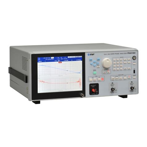
NF FRA51602 User manual

NF Corporation
GAIN-PHASE ANALYZER
FRA
51602
INSTRUCTION MANUAL
(OPERATIONS)


GAIN-PHASE ANALYZER
FRA
51602
INSTRUCTION MANUAL
(OPERATIONS)
DA00061635-001

Registered Trademarks
National Instruments, LabVIEW, and Measurement Studio are registered trademarks of National
Instruments Corporation in the United States.
WINDOWS® EMBEDDED 8.1 INDUSTRY PRO
Used with permission from Microsoft.
Other company names and product names used in this instruction manual may be trademarks or
registered trademarks of their respective companies.
Copyright
NI Measurement Studio
Copyright (C) 2010 National Instruments Corporation
All Rights Reserved.

i FRA
51602
──── Preface ────
Thank you for purchasing the "FRA
51602 GAIN-PHASE ANALYZER".
For safe and correct use of this product, please read the "Safety Precautions" section that follows
before attempting to use the instrument.
■Marks and symbols
For safe operation by the user and to prevent damage to the instrument, please give attention to the
following marks and symbols that are used in this manual.
!
WARNING
This mark indicates information for preventing the possibility of death or serious
personal injury from electrical shock or other hazards or damage to the instrument
in the use or handling of this instrument.
!
CAUTION
This mark indicates information for preventing the possibility of injury to the user or
damage to the instrument and the use for handling of this instrument.
■The scope of this Manual
This manual describes the FRA
51602 that conform to requirements of CE Marking.
Products without CE Marking affixed, may not meet derectives for CE Marking (EMC and others).
Please confirm the CE Marking is affixed on the rear panel.

Preface
ii FRA
51602
The manuals provided for the FRA
51602 are listed below.
●Instruction manual (Operations)
This manual describes operation of the FRA
51602 from the instrument’s control panel,
specifications, maintenance, and other basic matters.
●Instruction manual (Remote Control)
This manual describes remote control of the FRA
51602
The chapters of this manual are described below
If you’re using this equipment for the first time, begin reading from Chapter 1.
1. Introduction
This chapter provides a general description of the instrument, including its features,
applications, functions, and basic operating principles.
2. Preparation before use
This chapter describes important preparation that must be done before operating the
instrument.
3. Panel operations
This chapter explains the function, operating procedure, default values, and measurement
values for each part of the display screen. Read this chapter for a quick overall understanding
of the panel and its use.
4. Basic operation
This chapter explains the basic operating procedures of the FRA
51602. Refer to this chapter
as you use the instrument.
5. Advanced operation
This chapter explains a wider range of operations.
6. File formats
This chapter explains the various file formats for saving data in external storage devices
(USB memory).
7. Troubleshooting
This chapter describes how to deal with error messages and cases in which you think the
instrument is malfunctioning.
8. Maintenance
This chapter explains maintenance, repacking, transportation, and performance testing
methods.
9. Specifications
This chapter describes the instrument specifications (functions and performance).

iii FRA
51602
──── Safety Precautions ────
For safe use of this product, give full attention to the following warnings and cautions.
The NF Corporation shall not be held liable for damages that arise from failure to observe these warnings
and cautions.
This product is a Class I device (with protective conductor terminals) that conforms to the IEC insulation
standards.
Be sure to observe the instructions in the instruction manual.
This instruction manual contains information for the safe operation and use of this product.
Read the instructions and information before using the product.
All of the warning items contained in this instruction manual are intended to avoid risks that may lead
to serious accidents. Follow the warnings and instructions carefully.
Be certain that the product is properly grounded.
This product uses a line filter which may cause electric shock if the product is not grounded.
To prevent electrical shock accidents, connect the product to an earth ground so that ground resistance
is 100 or less.
This product is automatically grounded by connecting a 3-pin power plug to a power outlet with a
protective ground contact.
This product does not come with an accessory 3-pin to 2-pin power adapter. If you must use your own
adapter, be sure to connect the ground line of the adapter to a suitable ground near the power outlet.
Check the power supply voltage.
This instrument operates on the power source voltage described in "2.3 Grounding and Power
Connections".
Before plugging in the power cord, confirm that the outlet voltage conforms to the rated voltage of
this instrument.
If you think something is wrong, ...
If smoke or an unusual odor or sound comes from the instrument, immediately remove the power cord
from the socket and cease use of the instrument.
If any such abnormality occurs, take measures to prevent the use of the instrument until repairs have
been completed and promptly contact the NF Corporation or its authorized agent.
Do not use this product when gas is present.
Operating the instrument in the presence of flammable gases may cause an explosion.
Do not open the product case.
To prevent exposure to high voltages, never remove the cover of the instrument.
Only technicians certified by the NF Corporation are authorized to inspect or touch anything inside
the product case.

Safety Precautions
iv FRA
51602
Do not modify this product.
Never modify this product in any way. Modification might create new risks. The NF Corporation may
refuse to service an instrument that has an unauthorized modification.
Do not expose this product to water.
Use of this product when it is wet may result in electrical shock or fire. If the instrument becomes wet,
immediately unplug the power cord and contact the NF Corporation or its authorized agent.
If lightning occurs nearby, turn off the power switch and unplug the power cord.
A lightning strike may cause electrical shock, fire, or instrument malfunction.
Safety related symbols
The marks and codes defined below are used in this manual or on the instrument itself to indicate
safety information or instructions.
!
Instruction manual reference symbol
This notifies the user of a potential hazard and indicates that the user must
refer to the instruction manual.
Electric shock danger symbol
This symbol indicates a location that presents a risk of electric shock under
specific conditions.
Warning symbol
This contains information to avoid risks when handling the equipment that
could result in the death or serious injury of the operator.
Caution symbol
This contains information to avoid risks when handling the equipment that
could result in minor or moderate injury of the operator or damage to
property.
Other symbols
Indicates that the "ON" position of the power switch
Indicates the "OFF" position of the power switch
Indicates that the outer conductor of the connector is connected to the instrument
enclosure.
Indicates that the outer conductor of the connector is insulated from the instrument
enclosure.
However, safe operation of the instrument requires that the potential difference from the
grounding potential is restricted to 42 Vpk or less.
Indicates that the outer conductor of the connector is insulated from the instrument
enclosure.
However, the potential difference from ground or from the line neutral point must be 600
V or less and restricted to MEASUREMENT CATEGORY II at the mains.
This product is grounded when in use, so the electrical potential of the instrument enclosure is equal to
the ground potential.
!
CAUTION
!
WARNING
600V
CAT II
42Vpk

Safety Precautions
v FRA
51602
MEASUREMENT CATEGORIES
MEASUREMENT CATEGORIES specified by IEC61010-2-030:2017 may be specified for the
measurement connectors and other connectors of this instrument based on the location on the mains
that is being measured. The relevant MEASUREMENT CATEGORIES are listed below.
MEASUREMENT CATEGORY IV (CAT IV):
Circuits connected to the source of the building's low-voltage mains installation
MEASUREMENT CATEGORY III (CAT III):
Circuits connected to the distribution part of the building's low-voltage mains installation
MEASUREMENT CATEGORY II (CAT II):
Circuits connected directly to utilization points of the low-voltage mains installation
No MEASUREMENT CATEGORY:
Circuits not intended to be directly connected to the mains
Electromagnetic compatibility
This product is a CISPR 11 Group 1 Class A compliant instrument. It should not be used outside
industrial environments. Use of this product in ordinary office or residential areas may result in
electromagnetic interference with other devices.
Disposal of this product
To protect the environment, follow the guidelines described below for the disposal of this product.
a) This device is equipped with a lithium battery. Use the services of an industrial waste disposal
contractor to dispose of such batteries.
b) The LCD backlight module that is used in this product does not contain mercury.
c) Use the services of an industrial waste disposal contractor for disposal of the entire product.

vi FRA
51602
Contents
Page
1. Introduction................................................................................................................................ 1-1
1.1 Features..............................................................................................................................1-2
1.2 Applications........................................................................................................................1-3
1.3 Operating principles............................................................................................................1-6
2. Preparation before use.............................................................................................................. 2-1
2.1 Checking before use ..........................................................................................................2-2
2.2 Installation...........................................................................................................................2-5
2.3 Grounding and power connections ..................................................................................2-11
2.4 Quick operation check......................................................................................................2-13
2.5 Calibration.........................................................................................................................2-14
3. Panel operations ....................................................................................................................... 3-1
3.1 Function and use of each part of the panels......................................................................3-2
3.2 Input and output connectors...............................................................................................3-9
3.3 Outline of operation screen..............................................................................................3-20
3.4 Operation tree...................................................................................................................3-33
3.5 Operation screen reference..............................................................................................3-39
3.6 Initial settings....................................................................................................................3-84
4. Basic operation.......................................................................................................................... 4-1
4.1 Display and operation for powering up...............................................................................4-2
4.2 Simple operation for the first use .......................................................................................4-5
4.3 Oscillator settings.............................................................................................................4-14
4.4 Integration.........................................................................................................................4-18
4.5 Measurement control........................................................................................................4-20
4.6 Graph display mode.........................................................................................................4-22
4.7 High-frequency measurements........................................................................................4-25
5.Advanced operation................................................................................................................... 5-1
5.1 Analysis mode....................................................................................................................5-2
5.2 Delay...................................................................................................................................5-3
5.3 Input settings......................................................................................................................5-5
5.4 Oscillator control.................................................................................................................5-8
5.5 Graph display ...................................................................................................................5-12
5.6 Marker operations.............................................................................................................5-20
5.7 Amplitude compression....................................................................................................5-26
5.8 Automatic high density sweep..........................................................................................5-29
5.9 Error correction.................................................................................................................5-31

Contents
vii FRA
51602
5.10Differentiation and integration function.............................................................................5-39
5.11Sequence measurement..................................................................................................5-40
5.12Memory operations...........................................................................................................5-42
5.13External reference clock...................................................................................................5-52
5.14Other operations...............................................................................................................5-54
6. File formats................................................................................................................................ 6-1
6.1 Overview.............................................................................................................................6-2
6.2 Measurement data file format.............................................................................................6-2
6.3 Measurement conditions file format...................................................................................6-6
6.4 Screen capture file format................................................................................................6-10
7. Troubleshooting......................................................................................................................... 7-1
7.1 Error messages..................................................................................................................7-2
7.2 Information messages........................................................................................................7-6
7.3 Quick diagnosis..................................................................................................................7-8
8. Maintenance.............................................................................................................................. 8-1
8.1 Introduction.........................................................................................................................8-2
8.2 Daily maintenance..............................................................................................................8-3
8.3 Storage, repacking, and transportation..............................................................................8-3
8.4 Checking the version number.............................................................................................8-3
8.5 Performance test................................................................................................................8-4
8.6 Calibration.........................................................................................................................8-14
9. Specifications ............................................................................................................................ 9-1
9.1 Oscillator section................................................................................................................9-2
9.2 Analysis input section.........................................................................................................9-4
9.3 Measurement processing section ......................................................................................9-6
9.4 Analysis processing section...............................................................................................9-9
9.5 Display section .................................................................................................................9-14
9.6 Memory.............................................................................................................................9-14
9.7 External memory ..............................................................................................................9-15
9.8 External input/output function...........................................................................................9-15
9.9 Miscellaneous specifications............................................................................................9-17

viii FRA
51602
Figures and Tables
Page
Figure 1-1 Example of gain-phase characteristic measurement................................................ 1-3
Figure 1-2 Example of loop gain measurement ......................................................................... 1-4
Figure 1-3 Example of impedance characteristic measurement................................................ 1-5
Figure 1-4 Principal of frequency transfer characteristic measurement with the FRA
51602.... 1-6
Figure 1-5 Block diagram............................................................................................................ 1-7
Figure 2-1 Rack mounting kit assembly diagram (JIS) .............................................................. 2-7
Figure 2-2 Rack mounting kit assembly diagram (EIA).............................................................. 2-8
Figure 2-3 Rack mounting kit dimensions (JIS).......................................................................... 2-9
Figure 2-4 Rack mounting kit dimensions (EIA)....................................................................... 2-10
Figure 3-1 Front panel................................................................................................................ 3-2
Figure 3-2 Rear panel................................................................................................................. 3-3
Figure 3-3 Isolation rating of the analyzer input connectors...................................................... 3-9
Figure 3-4 Isolation withstand voltage of the analysis module input connectors by
frequency ................................................................................................................ 3-10
Figure 3-5 Maximum input voltage of the analysis module input connectors by frequency.....3-11
Figure 3-6 Isolation rating of the oscillator output connector................................................... 3-12
Figure 3-7 Isolation withstand voltage of the oscillator output connector by frequency .......... 3-13
Figure 3-8 Isolation withstand voltage between signal connectors.......................................... 3-14
Figure 3-9 Isolation withstand voltage between the signal connectors by frequency.............. 3-15
Figure 3-10 Screen immediately after startup.......................................................................... 3-20
Figure 3-11 Top menu............................................................................................................... 3-22
Figure 3-12 Top menu switching............................................................................................... 3-22
Figure 3-13 Example of a settings dialog................................................................................. 3-23
Figure 3-14 Navigating the menu hierarchy............................................................................. 3-23
Figure 3-15 Graph display styles.............................................................................................. 3-32
Figure 4-1 Connections for loop gain measurement.................................................................. 4-6
Figure 4-2 Example of connections for measuring the loop gain of a DC-DC converter........... 4-6
Figure 4-3 Nyquist plots obtained from actual measurements................................................... 4-9
Figure 4-4 Example of connections for gain-phase measurement.......................................... 4-10
Figure 4-5 Example of connections for transfer characteristic measurement.......................... 4-10
Figure 4-6 Example of connections for measuring impedance.................................................4-11
Figure 4-7 Example of connections for measuring impedance with high-power..................... 4-13
Figure 5-1 Example of a response waveform that requires a delay........................................... 5-3
Figure 5-2 Change in output voltage for the SLOW setting....................................................... 5-8
Figure 5-3 Oscillation stop mode setting and change in output voltage.................................... 5-9

Figures and Tables
ix FRA
51602
Figure 5-4 Frequency change mode and waveform change ................................................... 5-10
Figure 5-5 Graph display styles................................................................................................ 5-12
Figure 5-6 Example of phase measurements .......................................................................... 5-16
Figure 5-7 Example of marker search (Bode plot, MAX / MIN / PEAK / BOTTOM) ................ 5-21
Figure 5-8 Example of marker search (Bode plot, Y1 VALUE)................................................ 5-22
Figure 5-9 Example of marker search (Bode plot, ⊿Y1 VALUE)............................................ 5-22
Figure 5-10 Example of marker search (Nyquist plot, X MAX / PEAK / VALUE)..................... 5-22
Figure 5-11 Example of marker search (Nyquist plot, ⊿X)..................................................... 5-23
Figure 5-12 Example of using amplitude compression (gain-phase measurement) ............... 5-26
Figure 5-13 Example of using amplitude compression (impedance measurement)................ 5-26
Figure 5-14 Operation for amplitude......................................................................................... 5-27
Figure 5-15 Example of measurement using the automatic high density sweep .................... 5-29
Figure 5-16 Error correction data flow...................................................................................... 5-31
Figure 5-17 Connections for calibration ................................................................................... 5-32
Figure 5-18 Example of connections for gain-phase measurement........................................ 5-36
Figure 5-19 Example of connections for systematic error........................................................ 5-36
Figure 5-20 Conversion among displacement, speed, and acceleration by differentiation
and integration ........................................................................................................ 5-39
Figure 6-1 Structure of the measurement data file (no sequence measurement)..................... 6-2
Figure 6-2 Structure of the measurement data file (with sequence measurement)................... 6-3
Figure 6-3 Structure of the measurement conditions file ........................................................... 6-6
Figure 9-1 Isolation voltage specifications relative to the enclosure.......................................... 9-5
Figure 9-2 Isolation voltage specifications between signal connectors..................................... 9-6
Figure 9-3 External dimensions................................................................................................ 9-18

Figures and Tables
x FRA
51602
Table 2-1 Packing list.................................................................................................................. 2-2
Table 3-1 Initial settings 1/8...................................................................................................... 3-84
Table 4-1 Display modes .......................................................................................................... 4-22
Table 4-2 Graph axis parameters............................................................................................. 4-23
Table 4-3 Display parameter conversion formulas................................................................... 4-24
Table 6-1 Data file format (header)............................................................................................. 6-3
Table 6-2 Data file format (measurement conditions part)......................................................... 6-4
Table 6-3 Data file formats (measurement data part)................................................................. 6-5
Table 6-4 Measurement conditions file format (header)............................................................. 6-6
Table 6-5 Measurement conditions file format (measurement conditions part)......................... 6-6
Table 7-1 Power-up errors.......................................................................................................... 7-2
Table 7-2 Panel operation errors................................................................................................ 7-3
Table 7-3 Errors that occur during measurement....................................................................... 7-4
Table 7-4 Other errors................................................................................................................. 7-5
Table 7-5 Messages presented at start-up................................................................................. 7-6
Table 7-6 Messages presented during operation....................................................................... 7-6
Table 7-7 Troubleshooting.......................................................................................................... 7-8

1-1FRA
51602
1. Introduction
1.1 Features................................................................................1-2
1.2 Applications...........................................................................1-3
1.3 Operating principles..............................................................1-6
1.3.1 Basic principles............................................................1-6
1.3.2 Block diagram..............................................................1-7

1.1 Features
1-2FRA
51602
1.1 Features
The "FRA
51602 GAIN-PHASE ANALYZER" measures the loop gain frequency characteristics of
circuits such as inverters and switching power supplies by frequency sweeping. The instrument has a sweep
oscillator that uses the synthesizer method for driving the circuit being measured, an analyzer for
measuring the response of the circuit being measured to the driving signal and obtaining gain and phase
data, and a display screen for presenting the results. In addition to measuring the loop gain of inverters,
switching power supplies, and DC-DC converters, and mechanical servo characteristics, the instrument can
also measure the gain-phase characteristics of electronic circuits.
(1) High accuracy and wide dynamic range
The internal oscillator of the instrument maintains high frequency accuracy and resolution by using the
synthesizer method. The analyzer ensures a wide dynamic range with a high-resolutionA/D converter and
an automatic ranging function.
(2) Isolated input and output connectors
The two analysis inputs and oscillator outputs are independently isolated from the instrument enclosure
(600 V CAT II/300 V CAT III).
(3) Wide frequency range (10 µHz to 2 MHz)
This instrument can measure across a 10 µHz to 2 MHz frequency range with a single sweep.
(4) Color LCD and touch panel
The frequency characteristic graph and measurement condition setting menu are displayed on a color LCD
that is equipped with a touch panel. Various settings and operations can be performed intuitively by
touching the screen.
(5) High-speed measurement (as fast as 0.5 ms per data point)
Frequency sweeping is performed at up to 0.5 ms per data point. This performance contributes to
shortening the Takt time.
(6) GPIB/USB/RS-232/LAN interface as standard equipment
It is possible to set measurement conditions and read measurement data with an external personal computer.

1.2 Applications
1-3FRA
51602
1.2 Applications
This instrument features isolated input and output and highly-accurate measurement over a wide dynamic
range, enabling application in a variety of fields such as those listed below.
●Power electronics Loop characteristic measurement of inverters, switching power
supplies, etc.
●Contactless power supplies Frequency characteristic measurement of transmission coils and
driver amplifiers
●Servo systems Servo characteristic measurement of optical disk drives, robots,
camera lens control systems, etc.
●Electronic circuits Frequency characteristic measurement of filters, and amplifiers,
etc.
Loop characteristic measurement of DC-DC converters
●Electronic components Frequency characteristic measurement of coils, capacitors, and
other electronic components
●Audio equipment Frequency characteristic measurements of speakers, microphones,
etc.
●Vibration analysis Measurement of resonance characteristics
■Example of gain-phase characteristic measurement
An example of measuring frequency response characteristics (gain-phase characteristics) for amplifiers,
filters, and other such circuits is illustrated in Figure 1-1. The setup includes the sweep oscillator (OSC),
the equipment under test (EUT), and two measurement channels (CH1 and CH2).
The gain and phase of the EUT are obtained by measuring the input voltage from CH2, measuring the
output voltage from CH1, and dividing the measured output voltage by the input voltage. By taking the
measurements while sweeping the OSC frequency, the frequency characteristic is obtained automatically
and displayed in graph form on the LCD of the instrument.
Figure 1-1 Example of gain-phase characteristic measurement
EUT
CH1
CH2
OSC

1.2 Applications
1-4FRA
51602
■Example of loop gain characteristic measurement
The loop gain characteristic is obtained by injecting a perturbance signal into a negative feedback loop and
measuring the response to the perturbance signal.
The internal signal generator of the instrument is in a floating state with respect to the enclosure, so it is
possible to measure the linking characteristic without using an isolation transformer for signal injection.
The high withstand voltage isolation of up to 600 V (CAT II) enables measurement on the primary side of
inverters and switching power supplies that are connected directly to the mains.
Figure 1-2 Example of loop gain measurement
By measuring the characteristics with this instrument, it is possible to obtain the phase margin, gain margin,
and other indices that are needed to determine negative feedback loop stability.
+
A
β
input
output
v2
v1
=v2×Aβ
~
PWM
Vref
ErrorAmp
CH1
CH2
OSC
LOAD
(EUT)
switching power supply
-
-
-
+
+
+

1.2 Applications
1-5FRA
51602
■Example of impedance characteristic measurement
The impedance of the DUT can be measured by using this instrument to measure the voltage (v) with CH1
and the current (i) with CH2, and calculating the impedance by taking the vector ratio of CH1 and CH2.
The current of the DUT (i) is converted to a voltage with a shunt resistance, current probe, or CT, etc., and
the voltage is input to CH2. An impedance of 1 ohm is represented as a gain factor of 1 (0 dB).
Figure 1-3 Example of impedance characteristic measurement
It is possible to measure the impedance of the DUT at high voltage or large current by amplification of the
output of the sweep oscillator with the power amplifier as needed. This instrument differs from LCR meters,
impedance analyzers, and other such devices that limit the signal level to less than 1 V in that measurement
is possible under the signal amplitude conditions actually used by the EUT, thus enabling evaluation of
materials that handle high energy levels, such as magnets and dielectrics.
v
POWERAMPLIFIER
(OPTION)
i
CT
CH2
OSC
CH1
Z=v/i=V1/V2 x KCT
( KCT=V2/i )
V1
V2
DUT
(Z)

1.3 Operating principles
1-6FRA
51602
1.3 Operating principles
1.3.1 Basic principles
This instrument measures the frequency transfer characteristics of the equipment under test (EUT) with
high accuracy over a wide dynamic range. It is equipped with a sweep oscillator and two analysis input
channels (CH1,CH2), and makes highly-accurate calculations of analysis frequency component vectors
(amplitude and phase) from Fourier coefficients obtained from a discrete Fourier transform of the input
signals. By measuring the EUT input signal (Vin) and output signal (Vout) with the analysis input channels
(CH1 and CH2) and calculating the vector ratio (CH1/CH2), the gain and phase at the analysis frequency
(f) of the EUT can be obtained.
Figure 1-4 Principal of frequency transfer characteristic measurement with the FRA
51602
The loop characteristic measurement and impedance characteristic measurement both differ from the
frequency response measurement only in the connections and the units of the measurement results, so the
measurement principle is the same as for the frequency response measurement described above.
One round of measurement produces the gain and phase values at the analysis frequency (f). By measuring
the gain and phase while sweeping the oscillator and analysis frequencies, frequency characteristics such as
Bode plots can be obtained.Also, when auto-range is set, the range of the analysis module is optimized for
each frequency being measured, so the dynamic range is greatly increased for measurement ofA/D
converters.
~
A/D
A/D
OSC
CH1
CH2
EUT
DFT
DFT
Frequency
= f
V2(f)
V1(f)
|Gain(f)| = |V1(f)| ÷|V2(f)|
Phase(f) = ∠V1(f) -∠V2(f)
Vin
Vout
FRA51602
Other manuals for FRA51602
1
Table of contents
Other NF Measuring Instrument manuals

