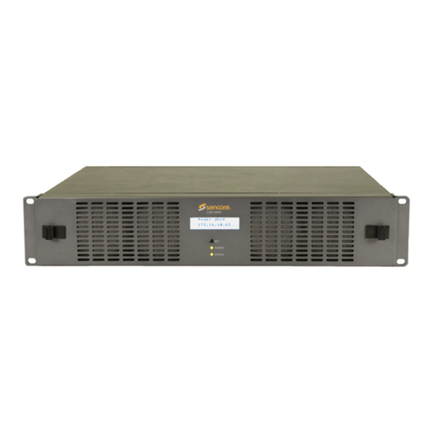
NF ZM2376 User manual

NF Corporation
LCR METER
ZM2376
Instruction Manual (Basics)


LCR METER
ZM2376
Instruction Manual (Basics)
DA00042208-005

Registered Trademarks
National Instruments and LabVIEW are registered trademarks of National Instruments
Corporation in the United States.
Other company names and product names used in this Instruction Manual may be trademarks or
registered trademarks of respective companies.
f

iZM2376
Preface
Thank you very much for purchasing our “ZM2376 LCR METER”.
Please read, first of all, "Safety Precautions" on the follawing pages, to use the instrument in the
correct and safe manner.
Caution Symbols Used in This Manual
The following caution symbols are used in this manual. Be sure to observe these caution symbols and
their contents to ensure the safety of the user and avoid damage to the equipment.
!
WARNING
Equipment handling could result in death or serious injury. This symbol contains
information to avoid such risk.
!
CAUTION
Equipment handling could result in minor or moderate injury or property damage. This
symbol contains information to avoid such risk.
The scope of this Manual
This manual describes the ZM2376 with the firmware version 1.00 or more and CE Marking.
Please make sure the CE marking on the rear panel.
Please watch the version that appears at the power-on.

Preface
ii ZM2376
The following instruction manuals are provided for ZM2376.
ZM2376 Instruction Manual (Basics)
This manual describes basic items such as how to operate ZM2376 from the panel,
specifications, and maintenance.
ZM2376 Instruction Manual (Remote Control)
This manual describes how to remote control ZM2376.
It includes the description of standard commands (ZM2376 primary commands).
ZM2376 Instruction Manual (Alternative Commands)
This manual describes the alternative commands of ZM2376.
If you find the alternative commands easier to use than the standard commands, you can use
them. However, the alternative command provides limited functions.
This manual (Basics) has the following chapters.
If using this equipment for the first time, start from Chapter 1.
1. OUTLINE
This chapter describes the overview, specificities, applications, functions and simple principle of
operations of this product.
2. PREPARATIONS BEFORE USE
This chapter describes important preparation before installation and operation.
3. PANEL FEATURES AND BASIC OPERATIONS
This chapter describes the functions and basic operations available for each panel screen part.
Read while operation the instrument.
4. ADVANCED OPERATIONS
This chapter describes even further the instrument operation.
5. TROUBLESHOOTING
This chapter describes how to deal with error messages and troubles.
6. MAINTENANCE
This chapter describes storage, repacking transportation as well as performance testing.
7. SPECIFICATION
This chapter describes the product’s specifications (functions and performance).

Safety Precautions
iii ZM2376
———— Safety Precautions ————
To ensure safe use, be sure to observe the following warnings and cautions.
NF Corporation shall not be held liable for damages that arise from a failure to observe these warnings
and cautions.
This product is a Class I product (with protective conductor terminal) that conforms to the IEC insulation
standards.
Be sure to observe the contents of instruction manual.
This instruction manual contains information for the safe operation and use of this product.
Be sure to read this information first before using this product.
All the warning items contained in this instruction manual are intended for preventing risks
that may lead to serious accidents. Ensure to obey them.
Be sure to ground the product.
This product uses a line filter, which may cause electric shock if the product is not
grounded.
To prevent electric shock accidents, connect it to an earth ground so that ground resistance
is 100Ω or less.
Check the power supply voltage.
This product operates on the power supply voltage indicated in “Grounding and Power
Supply Connection”in this instruction manual.
Prior to connecting the power supply, check that the voltage of the power outlet matches
the rated power supply of the product.
In case of suspected anomaly
If this product emits smoke, an abnormal smell, or abnormal noise, immediately power it
off and stop using it.
If such an abnormal occurs, prevent anyone from using this product until it has been
repaired, and immediately report the problem to NF Corporation or one of our
representatives.
Do not use this product when gas is present.
An explosion or other such hazard may result.
Do not remove the cover.
This product contains high-voltage parts. Absolutely never remove its cover.
Even when the inside of this product needs to be inspected, do not touch the inside. All
such inspections are to be performed by service technicians designated by NF Corporation.

Safety Precautions
iv ZM2376
Do not modify this product.
Never modify or try to modify the instrument. Your modification of the instrument could
cause unexpected accidents or failures. NF Corporation has the right to refuse providing
services for any instruments modified by unauthorized persons.
Do not expose this product to water.
When this product is used in wet condition, it may cause an electric shock and a fire. If
this product is exposed to water, unplug the power cord immediately, and contact NF
Corporation or one of our representatives.
If lightning occurs, power off this product and unplug the power cord.
A lightning may cause an electric shock, a fire and a failure.
Safety-related symbols
The general definitions of the safety-related symbols used on this product and in the
instruction manual are provided below.
!
Instruction Manual Reference Symbol
This symbol is displayed to alert the user to potential danger and refer him/her
to the instruction manual.
Warning Symbol
This symbol indicates information for the avoidance of a hazard such as electric
shock that may endanger human life or cause injury during handling of the
equipment.
Caution Symbol
This symbol indicates information for the avoidance of damage to the
equipment during handling.
Other Symbols
This symbol indicates the “on”position of the power switch.
This symbol indicates the “off”position of the power switch.
Shows when connected to the housing.
———— Electromagnetic Compatibility ————
This product may cause interference if used in residential areas. Such use must be avoided unless the
user takes special measures to reduce electromagnetic emissions to prevent interference to the reception
of radio and television broadcasts.
———— Request about disposal ————
To protect the environment, ensure that this device is disposed of by an appropriate industrial waste
processor. This product does not use batteries or a backlight that contains mercury.
!
CAUTION
!
WARNING

vZM2376
Table of Contents
Page
1.OUTLINE··························································································1-1
1.1 Features···································································································1-2
1.2 Applications·······························································································1-3
1.3 List of Functions·························································································1-4
1.4 Principle of Operation··················································································1-5
2.PREPARATIONS BEFORE USE···························································2-1
2.1 Checking Before Use ··················································································2-2
2.2 Installation·································································································2-6
2.2.1 General Precautions for Installation····························································· 2-6
2.2.2 Installation Conditions ·············································································· 2-6
2.2.3 Rack Mounting························································································ 2-7
2.3 Grounding and Power Supply Connection ·····················································2-12
2.4 Simplified Operation Check ········································································2-13
2.5 Calibration·······························································································2-14
3.PANEL FEATURES AND BASIC OPERATIONS·······································3-1
3.1 Panel Component Names and Functions·························································3-2
3.2 Display at Power “ON”and Initial Settings ·······················································3-4
3.2.1 Check before Power “ON”········································································· 3-4
3.2.2 Displays and Indications at Power “ON”························································ 3-5
3.2.3 Initialization···························································································· 3-6
3.3 Operation Tree·························································································3-13
3.4 Connection of DUT ···················································································3-17
3.4.1 Measurement Terminals ········································································· 3-17
3.4.2 Connection to DUT················································································ 3-18
3.4.3 Precautions on Connection······································································ 3-19
3.5 Basic Operations······················································································3-21
3.5.1 Outline of Measurement Screen ······························································· 3-21
3.5.2 Basic Key Operations············································································· 3-22
3.5.3 Simplified Operating Method When You Use Instrument for the First Time········· 3-25
3.5.4 Initialization·························································································· 3-29
3.5.5 Setting of Measurement Parameters·························································· 3-30
3.5.5.1 Selection of Primary Parameters ································································ 3-30
3.5.5.2 Setting of Equivalent Circuit······································································· 3-32
3.5.5.3 Setting of Secondary Parameters ······························································· 3-33
3.5.6 Setting of Basic Measurement Conditions··················································· 3-35
3.5.6.1 Measurement Frequency·········································································· 3-35
3.5.6.2 Measurement Signal Level········································································ 3-36
3.5.6.3 Measurement range················································································· 3-37
3.5.6.4 Trigger·································································································· 3-43
3.5.6.5 Measurement speed················································································ 3-48
3.5.6.6 Correction of Measurement Error································································ 3-51
3.5.6.7 OPEN Correction ···················································································· 3-53
3.5.6.8 SHORT Correction ·················································································· 3-59
3.5.6.9 LOAD Correction····················································································· 3-63

Table of Contents
vi ZM2376
3.5.6.10 Cable Length Correction··········································································· 3-73
4.ADVANCED OPERATIONS··································································4-1
4.1 Measuring with Specific Voltage or Current (ALC)·············································4-2
4.2 Restricting the Variation of Measured Value (Averaging) ····································4-6
4.3 Displaying the Deviation from the Reference Value ···········································4-7
4.4 Sorting the Part (Comparator) ·····································································4-10
4.5 Connecting to the Part handler (Handler Interface)··········································4-20
4.6 Measuring with More Than One Condition (Multi-measurement) ························4-30
4.7 Changing the Contents Displayed on the Second Line of Measurement Screen
(Auxiliary Display)·····················································································4-37
4.8 Saving/Recalling the Setting and Correction Value into the Memory····················4-39
4.9 Setting the Contact Check··········································································4-41
4.10 Applying the DC Bias Voltage ·····································································4-44
4.11 Applying the DC Bias Current······································································4-51
4.12 Disabling the Key-Operation of Panel ···························································4-54
4.13 Changing the Settling Wait Time During Automatic Adjustment··························4-55
4.14 Initializing of All Settings ············································································4-56
4.15 Self-Diagnosis ·························································································4-59
4.16 Checking the Version ················································································4-60
4.17 Remote Control························································································4-61
4.18 Switching the Operation Mode (alternative command)······································4-62
5.TROUBLESHOOTING ········································································5-1
5.1 Error Message ···························································································5-2
5.1.1 Errors at Power ON·················································································· 5-3
5.1.2 Errors at Panel Operation·········································································· 5-4
5.1.3 Errors During Measurement······································································· 5-5
5.1.4 Measured Value Display in Case of Error······················································ 5-6
5.2 When the Device Appears to be a Problem······················································5-8
6.MAINTENANCE·················································································6-1
6.1 Preface·····································································································6-2
6.2 Daily Maintenance······················································································6-3
6.3 Storage, Repacking, and Transportation ·························································6-3
6.4 Checking Version Number············································································6-3
6.5 Checking Isolation ······················································································6-4
6.6 Performance Testing···················································································6-4
6.6.1 Measurement Frequency Accuracy ·····························································6-5
6.6.2 Measurement Signal Level Accuracy ··························································· 6-5
6.6.3 Voltage Monitor Accuracy·········································································· 6-6
6.6.4 DC Bias Voltage Accuracy········································································· 6-7
6.6.5 AC Impedance Measurement Accuracy························································6-8
6.6.6 DC Resistance Measurement Accuracy······················································ 6-13
6.7 Calibration·······························································································6-15

Table of Contents
vii ZM2376
7.SPECIFICATION················································································7-1
7.1 Specification······························································································7-2
7.2 External Dimensions ·················································································7-17

Table of Contents
viii ZM2376
Attached figures and tables
Page
Figure 1-1 Block Diagram······················································································· 1-5
Figure 2-1 Rack-mount assembly (mm-rack)······························································ 2-8
Figure 2-2 Rack-mount assembly (inch-rack) ····························································· 2-9
Figure 2-3 Size and dimensions of the rack-mount (mm-rack) ······································2-10
Figure 2-4 Size and dimensions of the rack-mount (inch-rack)······································2-11
Figure 3-1 Front panel··························································································· 3-2
Figure 3-2 Rear panel ··························································································· 3-3
Figure 3-3 Functions of measurement terminals ························································3-17
Figure 3-4 Connection to DUT················································································3-18
Figure 3-5 Capacitance to measurement signal level characteristics······························3-39
Figure 3-6 Measurement sequence·········································································3-43
Figure 3-7 Signal acquisition time ···········································································3-49
Figure 3-8 Terminal processing at OPEN correction ···················································3-54
Figure 3-9 Terminal processing at SHORT correction ·················································3-60
Figure 3-10 Connection circuit network for LOAD correction ··········································3-63
Figure 3-11 Measurement of LOAD standard value······················································3-70
Figure 3-12 Measurement of LOAD correction value ····················································3-71
Figure 4-1 Maximum capacitance measurable at constant voltage (typical value)·············· 4-5
Figure 4-2 Inductance range measurable at constant voltage (typical value)····················· 4-5
Figure 4–3 Output of comparator result ····································································4-11
Figure 4–4 Range setting and comparison when sorting into bins ··································4-16
Figure 4–5 Equivalent circuit of handler interface························································4-23
Figure 4–6 Handler interface operation timing····························································4-24
Figure 4–7 Dummy output timing·············································································4-29
Figure 4-8 Handler interface operation timing in the multi-measurement·························4-35
Figure 4-9 Example of external voltage bias circuit·····················································4-49
Figure 4-10 Example of external current bias circuit ·····················································4-51
Figure 7-1 Range of error······················································································7-11
Figure 7-2 LC - Z conversion graph·········································································7-12
Figure 7-3 ZM2376 external dimensions ··································································7-17

Table of Contents
ix ZM2376
Table 2-1 Package contents ·················································································· 2-2
Table 3-1 Setting items and initial values·································································· 3-7
Table 3-2 Measurement range list··········································································3-37
Table 3-3 Max. current, max. voltage, and output impedance
in each measurement range····································································3-39
Table 3-4 Example of measurement time (typical value)·············································3-48
Table 4-1 Display format of measured value and interpretation of setting value
(example of L)······················································································4-14
Table 4–2 Initialization contents of comparator··························································4-14
Table 4–3 Handler interface signal layout·································································4-20
Table 4–4 Functions of handler interface signal·························································4-21
Table 4-5 Handler interface output in the multi-measurement······································4-34
Table 5-1 When the device appears to be a problem ·················································5-11

1-1 ZM2376
1.OUTLINE
1.OUTLINE .........................................................................1-1
1.1 Features...........................................................................1-2
1.2 Applications......................................................................1-4
1.3 List of Functions...............................................................1-5
1.4 Principle of Operation.......................................................1-6

1.1 Features
1-2 ZM2376
1.1 Features
The “ZM2376 LCR Meter” is a high speed LCR meter with the maximum frequency 5.5MHz and
maximum signal level 5V. It has high basic accuracy of 0.08% and is capable of measuring the impedance
in a wide application range from manufacturing and inspection lines of electronic parts up to the research
of materials.
Measurement frequency 1mHz to 5.5MHz
The instrument has the maximum 6-digit resolution and thus it is capable of measuring the detailed
frequency characteristics of the DUT (Device Under Test).
Signal level 10mV to 5V / Maximum current 200mA
It is capable of measuring the characteristics of DUT in a wide signal level range.
Constant voltage / Constant current drive
It can make evaluation on stable signal level even for the DUT of which characteristics vary with
the signal level.
High speed measurement
It provides high speed measurement at the fastest 2ms (1kHz - 1MHz) or 10ms (120Hz).
Cable length 0m / 1m / 2m / 4m
Allowable length of connection cable to the DUT is maximum 4m. However, it is limited by the
frequency.
Triggered drive
A signal is output after the instrument contacted the DUT, thus reducing the contact damage when
high capacitance capacitor is measured. Also, this feature reduces measurement dispersion of the
DUT having hysteresis characteristics.
Contact check
A contact failure to DUT can be detected based on an abnormally low capacitance or abnormal
voltage/current signal, with little additional time required.
Handler interface
The bin sorting results of maximum 14 categories can be output to the part handler.
Remote control
The instrument is equipped with the USB, RS-232 (230.4kbps max), and GPIB interfaces as
standard, which is useful for installing it in production lines or measurement systems. A LAN
interface is also available optionally.

1.1 Features
1-3 ZM2376
DC (Direct-current) resistance measurement
Direct-current resistance such as a winding resistance of inductor or transformer can be measured.
Setting/correction value memory
32 sets of settings and correction values can be stored in nonvolatile memory, and they can be used
selectively.

1.2 Applications
1-4 ZM2376
1.2 Applications
Inspection, sorting, and evaluation test in production lines of electronic parts
such as inductors, capacitors, and sensors.
Evaluation and research of magnetic materials and dielectrics.
Impedance measurement of batteries.

1.3 List of Functions
1-5 ZM2376
1.3 List of Functions
The following shows the functional tree of ZM2376.

1.4 Principle of Operation
1-6 ZM2376
1.4 Principle of Operation
The ZM2376 gives sine wave signal from an internal oscillator to the DUT (Device Under Test). The
impedance bridge detects the current I flowing in DUT and the voltage V applied to DUT, and then the
main processor obtains the impedance Z (= V / I). The parameters such as inductance L, capacitance C,
resistance R, etc. are calculated from the impedance (magnitude, phase angle).
Figure 1-1 Block Diagram
Main Processor
According to the user’s operation, the main processor controls the oscillator and impedance bridge to
calculate the vector ratio from the voltage signal and current signal obtained from the DUT. Then, the
main processor makes necessary correction, and finally converts the data into the required parameter
to be displayed or output.
Main Processor
Panel
LCD Character Display,
Key & Lamp
GPIB
RS-232
Isolator
A/D
V
signal
Handler
Interface
DUT
I
signal
HCUR
HPOT
LPOT
LCUR
USB
Oscillator
Power
Amp
Frequency
Synthesizer
Amplitude
Control
DC Bias
Impedance
Bridge
R_range
diff-AMP
diff-AMP
DC canceller
LAN
(Option)

1.4 Principle of Operation
1-7 ZM2376
Oscillator
The oscillator generates sine wave signals having exact frequencies by means of a direct digital
frequency synthetic method based on the reference clock of crystal oscillator.
When the Automatic Level Control (ALC) function is effective, the main processor adjusts
automatically the signal level so that the voltage and current monitored values become the specified
values.
Impedance Bridge
The current flowing in the DUT is converted into the voltage by the range resistance and differential
amplifier. At this time, the potential of LCUR between LPOT terminals is maintained to almost zero by
automatic balancing motion of the bridge. Accordingly, the current that runs away to the ground
through capacitance to earth and insulation resistance and is not detected can be reduced.
The voltage applied to the DUT is detected by the differential amplifier.
After that, the voltage signal and current signal are converted into digital values by the A/D converter,
and sent to the main processor.
Other manuals for ZM2376
1
Table of contents
Other NF Measuring Instrument manuals
Popular Measuring Instrument manuals by other brands

Sper scientific
Sper scientific 850015 instruction manual
horiba
horiba LAQUA WQ-310 instruction manual
Tektronix
Tektronix 1720 instruction manual
Endress+Hauser
Endress+Hauser airtrol CPC 200 operating instructions
Agilent Technologies
Agilent Technologies 86142B user guide
GT LASERS
GT LASERS CYL-2000/S user manual
M-system
M-system 43DV1-S instruction manual
Berger & Schroter
Berger & Schroter LW800 PRO operating instructions
Pixsys
Pixsys 2000.35.021 user manual
Amprobe
Amprobe AT-2005-A quick guide

Milwaukee
Milwaukee MC510 user manual
PCB Piezotronics
PCB Piezotronics Imi Sensors ICP 602D02 Installation and operating manual
