NF FRA5022 User manual

NF Corporation
FREQUENCY RESPONSE ANALYZER
FRA5022
Instruction Manual


FREQUENCY RESPONSE ANALYZER
FRA5022
Instruction Manual
DA00016981-005

Registered Trademarks
National Instruments is a registered trademark of National Instruments
Corporation in the United States.
Other company names and product names may be trademarks or registered
trademarks of their respective companies.

FRA5022
i
―――Preface ―――
Thank you very much for purchasing our “FRA5022 FREQUENCY RESPONSE
ANALYZER”.
To ensure safe and proper use of this electric equipment, please read first
“Safety Precautions”on the following pages.
●Caution Symbols Used in This Manual
The following caution symbols are used in this manual. Be sure to observe these
caution symbols and their contents to ensure the safety of the user and avoid damage
to the equipment.
This symbol indicates information for the avoidance of a hazard such as electric shock
that may endanger human life or cause injury during handling of the equipment.
This symbol indicates information for the avoidance of damage to the equipment during
handling.
●This manual has the following chapter organization.
If using this equipment for the first time, start from Chapter 1.
1. OUTLINE
This chapter describes the overview, specificities, applications, functions and simple
principle of operations of this product.
2. PREPARATIONS BEFORE USE
This chapter describes important preparation before installation and operation.
3. PANEL FEATURES AND BASIC OPERATIONS
This chapter describes the functions and simple operations available for each panel
screen part.
Read while operation the device.
4. ADVANCED OPERATIONS
This chapter describes even further the device operation.
5. REMOTE CONTROL
This chapter describes remote control through GPIB or USB.
6. TROUBLESHOOTING
This chapter describes how to deal with error messages and troubles.
7. MAINTENANCE
This chapter describes storage, repacking, transportation as well as performance
testing.
8. SPECIFICATIONS
This chapter describes the product's specifications (functions and performance).
!
WARNING
!
CAUTION

FRA5022
ii
―――Safety Precautions ―――
To ensure safe use, be sure to observe the following warnings and cautions.
NF Corporation shall not be held liable for damages that arise from a failure to observe
these warnings and cautions.
This product is a Class I product (with protective conductor terminal) that conforms to the
JIS and IEC insulation standards.
●Be sure to observe the contents of this instruction manual.
This instruction manual contains information for the safe operation and use of this
product.
Be sure to read this information first before using this product.
All the warnings in the instruction manual must be heeded to prevent hazards that
may cause major accidents.
●Be sure to ground the product.
This product uses a line filter, which may cause electric shock if the product is not
grounded.
This product is automatically grounded when its three-pole power supply plug is
connected to a three-pole power outlet with a protective-ground contact.
●Check the power supply voltage.
This product operates on the power supply voltage indicated in “Grounding and Power
Supply Connection”in this instruction manual.
Prior to connecting the power supply, check that the voltage of the power supply
matches the rated power supply of the product.
●In case of suspected anomaly
If this product emits smoke, an abnormal smell, or abnormal noise, immediately power
it off and stop using it.
If such an anomaly occurs, prevent anyone from using this product until it has been
repaired, and immediately report the problem to NF Corporation or one of our
representatives.
●Do not use this product when gas is present.
An explosion or other such hazard may result.
●Do not remove the cover.
This product contains high-voltage parts. Absolutely never remove its cover.
Even when the inside of this product needs to be inspected, do not touch the inside. All
such inspections are to be performed by service technicians designated by NF
Corporation.

Safety Precautions
FRA5022
iii
●Do not modify this product.
Absolutely never modify this product, as this may cause new hazards and may
disqualify this product from repair in case of failure.
●Safety-related symbols
The general definitions of the safety-related symbols used on this product and in the
instruction manual are provided below.
Instruction Manual Reference Symbol
This symbol is displayed to alert the user to potential danger and refer
him/her to the instruction manual.
Electric Shock Danger Symbol
This symbol indicates locations that present a risk of electric shock
under specific conditions.
Warning Symbol
This symbol indicates information for the avoidance of a hazard
such as electric shock that may endanger human life or cause
injury during handling of the equipment.
Caution Symbol
This symbol indicates information for the avoidance of damage to
the equipment during handling.
●Other symbols
This symbol indicates the "on" position of the power switch.
This symbol indicates the "off" position of the power switch.
Shows when connected to the case.
Shows when connected to the ground.
●Note on Waste Processing
To protect the environment, ensure that this device is disposed of by an
appropriate industrial waste processor. Also note the following:
・This device includes lithium batteries.
!
WARNING
!
CAUTION
!

FRA5022
iv
Contents
Page
1.OUTLINE .......................................................................................................................1-1
1.1 Features...................................................................................................................1-2
1.2 Applications..............................................................................................................1-2
1.3 List of Functions.......................................................................................................1-3
1.4 Principle of Operation ..............................................................................................1-5
2.PREPARATIONS BEFORE USE ...................................................................................2-1
2.1 Checking Before Use...............................................................................................2-2
2.2 Installation................................................................................................................2-3
2.2.1 General Precautions for Intallation....................................................................2-3
2.2.2 Installation Conditions .......................................................................................2-3
2.2.3 Rack Mounting...................................................................................................2-4
2.3 Grounding and Power Supply Connection...............................................................2-9
2.4 Simplified Operation Check ...................................................................................2-10
2.5 Calibration.............................................................................................................. 2-11
3.PANEL FEATURES AND BASIC OPERATIONS ...........................................................3-1
3.1 Panel Component Names and Functions ................................................................3-2
3.2 Display at Power “ON” and Initial Settings...............................................................3-5
3.2.1 Check before Power “ON”.................................................................................3-5
3.2.2 Displays and Indications at Power “ON”............................................................3-6
3.2.3 Initialization........................................................................................................3-6
3.3 I/O Terminals............................................................................................................3-9
3.3.1 Oscillator Output Terminal .................................................................................3-9
3.3.2 Analyzer Input Terminal...................................................................................3-10
3.3.3 Signal Terminal Isolation..................................................................................3-11
3.4 I/O Connection.......................................................................................................3-12
3.5 Basic Operations....................................................................................................3-13
3.5.1 Simplified Sweep Measurement......................................................................3-13
3.5.2 Setup Screen, Measurement Screen Switchover............................................3-14
3.5.3 Menu Screen Basic Operation.........................................................................3-15
3.5.4 System Menu Screen ......................................................................................3-17
3.5.5 Sweep Menu Screen .......................................................................................3-20
3.5.6 Spot Menu Screen...........................................................................................3-27
3.5.7 Sweep Measurement.......................................................................................3-30
3.5.8 Sweep Measurement Screen ..........................................................................3-31
3.5.9 Spot Measurement ..........................................................................................3-32
3.5.10 Spot Measurement Screen............................................................................3-33
3.5.11 Measured Values of Excessive Input.............................................................3-34

Contents
FRA5022
v
4.ADVANCED OPERATIONS...........................................................................................4-1
4.1 Setup Screen ...........................................................................................................4-2
4.1.1 Setup Screen Display........................................................................................4-2
4.1.2 Sweep Setup Screen.........................................................................................4-2
4.1.3 Spot Setup Screen ............................................................................................4-3
4.1.4 Oscillator Setup Screen.....................................................................................4-3
4.2 Settings Memory......................................................................................................4-4
4.2.1 Setting Memory Description ..............................................................................4-4
4.2.2 Setting Memory Setup Items .............................................................................4-4
4.2.3 Setting Memory Operation.................................................................................4-5
4.3 Result Evaluation.....................................................................................................4-6
4.3.1 Evaluation Range Setting..................................................................................4-6
4.3.2 Evaluation Display.............................................................................................4-6
4.4 Scan Measurement..................................................................................................4-7
4.4.1 Scan Related Setup Items.................................................................................4-7
4.4.2 Scan Measurements Operation and Function ...................................................4-7
4.5 Servo System Measurement....................................................................................4-9
4.6 Data Memory..........................................................................................................4-12
4.7 Equalizer................................................................................................................4-13
4.8 Oscillator Output Terminal Change Rate Limit (SLOW).........................................4-14
5.REMOTE CONTROL .....................................................................................................5-1
5.1 Preparations Before Use..........................................................................................5-2
5.1.1 USB Preparations..............................................................................................5-2
5.1.2 GPIB Preparations.............................................................................................5-2
5.1.3 Remote Control Interface Selection ..................................................................5-2
5.1.4 USB Device Identification..................................................................................5-3
5.1.5 GPIB Address Setting........................................................................................5-3
5.1.6 Necessary Precautions When Using GPIB .......................................................5-3
5.2 Remote State Display and Cancellation ..................................................................5-3
5.3 Command List..........................................................................................................5-4
5.4 Command Tree ........................................................................................................5-9
5.5 Command Explanation...........................................................................................5-10
5.5.1 Summary of Terms...........................................................................................5-10
5.5.2 Command Detailed Explanations ....................................................................5-11
5.6 Status System........................................................................................................5-33
5.6.1 Status System Overview .................................................................................5-33
5.6.2 Status Byte ......................................................................................................5-34
5.6.3 Standard Event Status.....................................................................................5-35
5.6.4 Operation Status..............................................................................................5-37
5.6.5 Overload Status...............................................................................................5-39
5.7 Programming Cautions ..........................................................................................5-40

Contents
FRA5022
vi
6.TROUBLESHOOTING...................................................................................................6-1
6.1 Error Messages........................................................................................................6-2
6.1.1 Errors at Power-On............................................................................................6-2
6.1.2 Error During Panel Operation............................................................................6-3
6.1.3 Remote Control Errors.......................................................................................6-3
6.2 When Fault Symptoms are Observed......................................................................6-4
7.MAINTENANCE.............................................................................................................7-1
7.1 Introduction ..............................................................................................................7-2
7.2 Daily Maintenance....................................................................................................7-2
7.3 Storage, Repacking, and Transportation .................................................................7-2
7.4 Checking Version Number .......................................................................................7-3
7.5 Checking Isolation....................................................................................................7-3
7.6 Checking Oscillator Output Wave Form...................................................................7-3
7.7 Performance Testing ................................................................................................7-3
7.7.1 Frequency Accuracy Test ..................................................................................7-4
7.7.2 Oscillator AC Amplitude Accuracy Test..............................................................7-4
7.7.3 Oscillator DC Bias Accuracy Test ......................................................................7-4
7.7.4 Ratio Accuracy Test...........................................................................................7-5
7.7.5 IMRR Test..........................................................................................................7-6
7.7.6 Dynamic Range Test..........................................................................................7-6
7.8 Calibration................................................................................................................7-7
8.SPECIFICATIONS .........................................................................................................8-1
8.1 Oscillator..................................................................................................................8-2
8.2 Analyzer Input..........................................................................................................8-3
8.3 Analysis Processor ..................................................................................................8-3
8.4 Measurement Processing ........................................................................................8-4
8.5 Display Part..............................................................................................................8-5
8.6 Settings Memory......................................................................................................8-5
8.7 Remote Control Interface.........................................................................................8-5
8.8 General Information .................................................................................................8-6

FRA5022
vii
Attached figures and tables
Page
Figure 1-1 Block Diagram..................................................................................................1-5
Figure 2-1 Size and dimensions of the rack-mount (mm-rack) .........................................2-5
Figure 2-2 Size and dimensions of the rack-mount (inch-rack).........................................2-6
Figure 2-3 Mounting rack-mount adapter (mm-rack).........................................................2-7
Figure 2-4 Mounting rack-mount adapter (inch-rack)........................................................2-7
Figure 2-5 Removal of feet................................................................................................2-8
Figure 3-1 Front panel.......................................................................................................3-3
Figure 3-2 Rear panel........................................................................................................3-4
Figure 3-3 Oscillator output terminal .................................................................................3-9
Figure 3-4 Analyzer input terminal...................................................................................3-10
Figure 3-5 Insulation voltages of input and output terminals...........................................3-11
Figure 3-6 Connection with the system under test (SUT) ...............................................3-12
Figure 3-7 OSCILLATOR-CH1 internal connection.......................................................3-12
Figure 3-8 Setup screen, measurement screen switchover (description) .......................3-14
Figure 3-9 System menu screen .....................................................................................3-17
Figure 3-10 Sweep menu screen.....................................................................................3-20
Figure 3-11 Spot menu screen ........................................................................................3-27
Figure 3-12 Sweep measurement control keys ...............................................................3-30
Figure 3-13 Sweep measurement screen........................................................................3-31
Figure 3-14 Spot measurement control key ....................................................................3-32
Figure 3-15 Spot measurement screen...........................................................................3-33
Figure 4-1 Setup key .........................................................................................................4-2
Figure 4-2 Sweep setup screen (ex.) ................................................................................4-2
Figure 4-3 Spot setup screen (ex.)....................................................................................4-3
Figure 4-4 Oscillator setup screen (ex.) ............................................................................4-3
Figure 4-5 Evaluation result display ..................................................................................4-6
Figure 4-6 Scan measurement..........................................................................................4-7
Figure 4-7 Connection for servo system measurement.....................................................4-9
Figure 4-8 Measurement voltage range magnification example......................................4-11
Figure 4-9 Connection with equalizer..............................................................................4-13

FRA5022
viii
Figure 5-1 Command tree .................................................................................................5-9
Figure 5-2 Status system.................................................................................................5-33
Figure 5-3 Standard event status structure.....................................................................5-35
Figure 5-4 Operation status structure..............................................................................5-37
Figure 5-5 Overload status structure...............................................................................5-39
Figure 8-1 External dimensions.........................................................................................8-8
Table 2-1 Package Contents .............................................................................................2-2
Table 3-1 Setting items and initial values ..........................................................................3-7
Table 4-1 Setup items and screen handling ......................................................................4-4
Table 5-1 FRA5022 subsystem command list ...................................................................5-4
Table 5-2 Common command list......................................................................................5-7
Table 5-3 Status byte register definitions ........................................................................5-34
Table 5-4 Standard event status register contents ..........................................................5-35
Table 5-5 Operation condition register contents..............................................................5-38
Table 5-6 Overload event register contents.....................................................................5-39

FRA5022
1-1
1.OUTLINE
1.1 Features ······················································1-2
1.2 Applications··················································1-2
1.3 List of Functions ············································1-3
1.4 Principle of Operation ·····································1-5

1.1 Features
FRA5022
1-2
1.1 Features
“FRA5022 Frequency Response Analyzer” allows you to obtain the frequency response
characteristics (change of gain and phase vs frequency) of a system under test by
supplying sine wave signals to the system under test and by analyzing the response
signals.
•Oscillator frequency 0.1mHz to 100kHz
Covers the most suitable ranges to measure electrochemical impedance or analyze
mechanical system servo.
•2-channel simultaneous measurement
The 2-channel analyzer enables parallel signal reception, thus reducing the
measurement time at lower frequencies compared to devices that receive signals
sequentially via both channels.
•Input-Output isolation
The 2-channel analyzer input and the oscillator output are independently isolated
from the case, thus facilitating the signal supply to the system under test when in
servo analysis.
•Graph display
It is possible to display the frequency characteristics on a color liquid crystal display
as Bode diagrams.
•Quick settings switchover
It is possible to switchover preset settings by pressing one button.
•Slim type
With a height of only 88mm (2U), the device fits conveniently in a system rack.
•Data display software
The supplied software allows you to easily export data to a personal computer, save
data in CSV format, and display data as various graphs.
1.2 Applications
•Servo systems
Measurement of servo characteristics of systems such as CD/DVD players, etc.
•Electronic circuits
Measurement of frequency characteristics of systems such as filters, amplifiers, etc.
•Acoustics
Measurement of frequency characteristics of systems such as speakers, microphones,
etc.
•Vibration analysis
Measurement of resonance characteristics
•Electrochemicals
Metallic corrosion studies, battery performance measurement (electrochemical
impedance measurement)

1.3 List of Functions
FRA5022
1-3
1.3 List of Functions
Below is a tree listing of available functions.
Oscillator SLOW
AC/DC ON
AC/DC OFF
AC OFF
Frequency
AC amplitude
DC bias
rms/peak switching
Sweep measurement UP
DOWN
HOLD
STOP
Frequency scale
Maximum frequency
Minimum frequency
Frequency point
Automatic/Manual switching
Spot measurement SPOT: switching to spot display
Repeat/Single switching
Phase display lower limit
Gain passing range upper limit
Gain passing range lower limit
Phase passing range upper limit
Phase passing range lower limit
Scan
Measurement settings Measurement mode CH2/CH1
CH2/OSC
Integration time
Integration cycle
Delay time
Data memory control Display mode A
B
A&B
A/B
Store to memory B
1.3 List of Functions
FRA5022
1-4
Graph display Display format GdB, P - F
G (linear), P - F
a - b (additional display of values)
Gain upper limit
Gain lower limit
Phase upper limit
Phase lower limit
Automatic scaling
Frequency axis magnification (MAG)
Cursor Cursor speed
Excessive input CH1 detection level
CH2 detection level
Action on detection OVER light up
BEEP
HOLD
OSC OFF
Settings memory Settings title
Settings lock
Settings initialization
Settings copy
One touch switching
System Self calibration
Total initialization
Scan upper limit
Automatic scan
Error reset
Switch to LOCAL
Interface Interface selection GPIB GPIB address
USB Serial No.
1.4 Principle of Operation
FRA5022
1-5
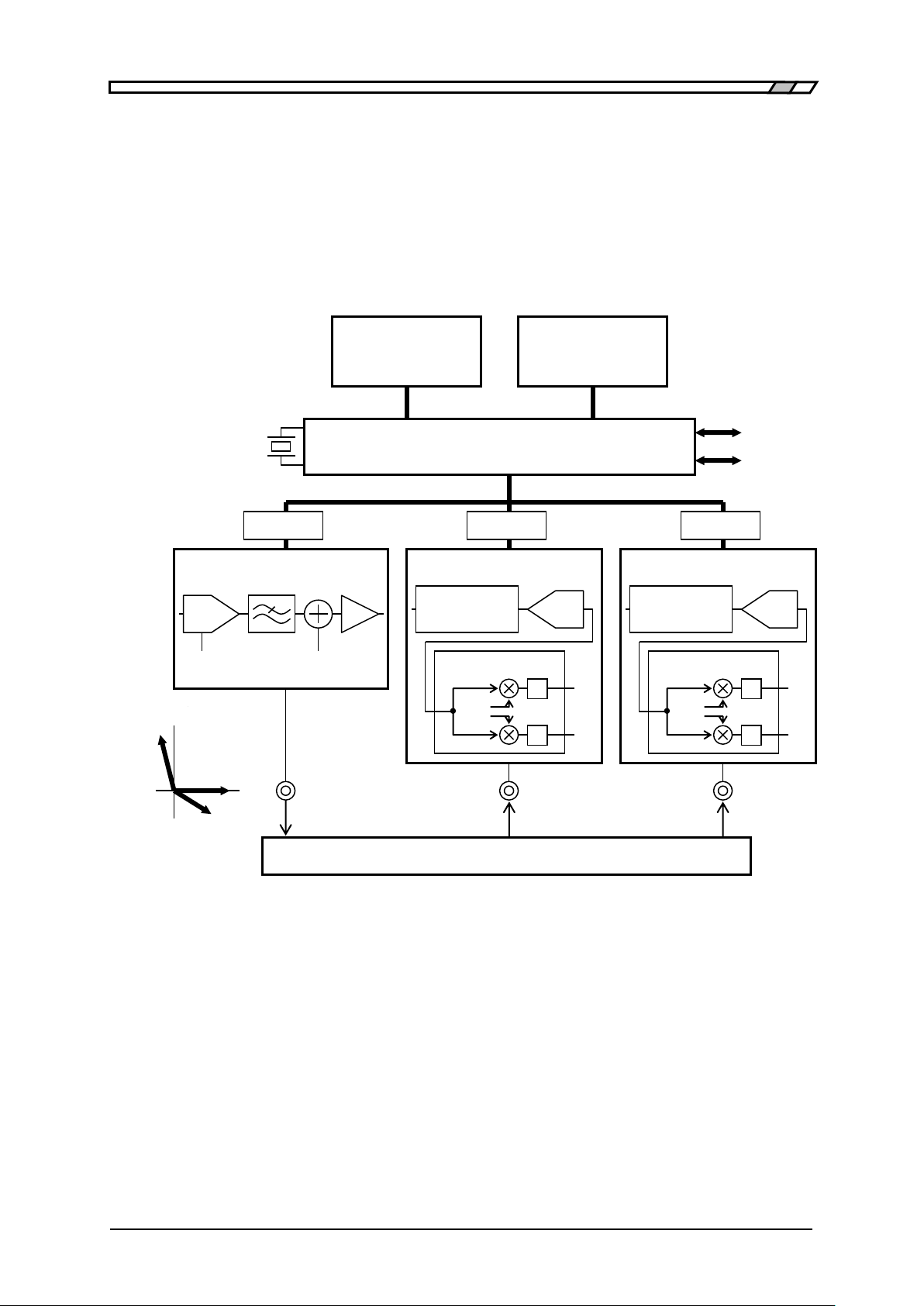
1.4 Principle of Operation
“FRA5022 Frequency Response Analyzer” obtains the vector ratio V2/V1of the response
signal V1and V2by supplying a sine wave test signal V0from its internal oscillator to the
system under test, more specifically, the gain G = |V2/V1|and phase differential
P = ∠V2-∠V1at a given frequency. Below are the block diagram and operation outline
of FRA5022.
Figure 1-1 Block Diagram
•Main Processor
According to the user’s operation, the main processor controls the oscillator and
analyzer to calculate, output, and display the vector ratio of the signals obtained by the
analyzer. By using the direct digital frequency synthesis method based on the reference
quarts-crystal resonator, the main processor generates accurately pitched digital sine
wave signals (Sin, Cos) to be used by the oscillator or analyzer.
•Oscillator
The FRA5022 oscillator converts digital sine signals to analog signals with D/A (Digital
to Analog) converters and filters. It also adds DC bias before output.
Main Processor
LCD
Color Display
Panel
Key & Lamp
GPIB
USB
Isolator
Isolator
Isolator
System Under Test
V0
V1
V2
Oscillator
DC Bias
D/A
Amplitude
V0
V1
V2
Signal vector
X
Y
Analyzer CH1
Sub Processor
Signal
Conditioner
A/D
Sin
Cos
X
Y
∫
∫
Analyzer CH2
Sub Processor
Signal
Conditioner
A/D
Sin
Cos
X
Y
∫
∫

1.4 Principle of Operation
FRA5022
1-6
•Analyzer
The analyzer performs, via the signal conditioner, appropriate adjustments such as level
adjustment on the response signals from the system under test, and converts them to
digital signals via the A/D (Analog to Digital) Converter. The subprocessor obtains the
two orthogonal components of the signal (the signal vectors) by multiplication and
integration of the response signal with orthogonal reference signals (Sin, Cos). This
process allows to attenuate frequency components that do not match the signal
frequency and thus render possible accurate measurements even with considerable
noise.

FRA5022
2-1
2.PREPARATIONS BEFORE USE
2.1 Checking Before Use······································2-2
2.2 Installation····················································2-3
2.2.1 General Precautions for Intallation················2-3
2.2.2 Installation Conditions································2-3
2.2.3 Rack Mounting ·········································2-4
2.3 Grounding and Power Supply Connection···········2-9
2.4 Simplified Operation Check····························2-10
2.5 Calibration·················································· 2-11

2.1 Checking Before Use
FRA5022
2-2
2.1 Checking Before Use
■Safety check
Before using FRA5022, make sure you read “Safety Precautions”, located at the
beginning of this instruction manual and observe the required cautions.
Before turning the power on, read “2.3 Grounding and Power Supply Connection”and
observe the necessary cautions.
■Unpacking
Check that the device has not been damaged during transit.
Before installing the device, make sure that the contents listed below in “Table 2-1
Package Contents”are supplied in the carton.
Table 2-1 Package Contents
The data display software allows you to easily import the data from FRA5022 to a
personal computer, save data in CSV format, display data as various graphs, and set main
parameters.
Instructions for using the CD-ROM contents are not contained in this manual. For details
on the contents, please refer to the instruction manual separately available in the
CD-ROM. To view the CD-ROM contents, Adobe Acrobat Reader Ver.5 or later must be
installed on your computer.
This device contains high-voltage parts. Never remove the cover.
The internal parts of this device must only be serviced by an engineer who
has a thorough understanding of risk prevention.
FRA5022 Body ································································ 1
Instruction Manual ························································· 1
Power Cord Set (3 Pole, 2m) ··············································· 1
CD-ROM ········································································ 1
Contents ・Data display software
・LabVIEW driver
・Sample program
!
WARNING
Table of contents
Other NF Measuring Instrument manuals


Popular Measuring Instrument manuals by other brands

Levenhuk
Levenhuk Wezzer Air MC20 user manual

GASTRON
GASTRON GPD-100 instruction manual

TechnipFMC
TechnipFMC Proline Promass F 500 Operating instructions manual

AEMC instruments
AEMC instruments 6536 user manual

TPI
TPI Amp Plus 296 instruction manual

VTI Instruments
VTI Instruments EX1401 operating instructions


