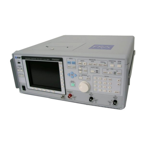
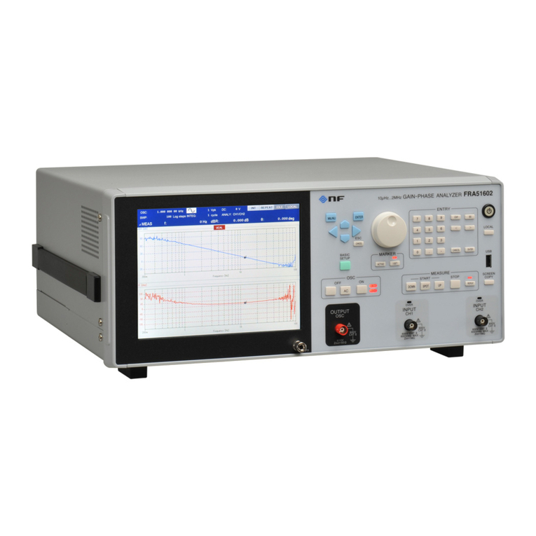
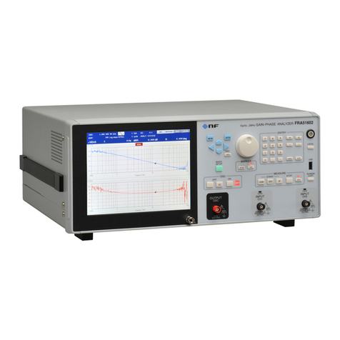
NF FRA51602 User manual

NF Corporation
GAIN-PHASE ANALYZER
FRA51602
Instruction Manual (remote control)


GAIN-PHASE ANALYZER
FRA51602
Instruction Manual (remote control)
DA00066613-001

RegisteredTrademarks
NationalInstruments,LabVIEW,andMeasurementStudioareregisteredtrademarksofNational
InstrumentsCorporationintheUnitedStates.
WINDOWS®EMBEDDED8.1INDUSTRYPRO
UsedwithpermissionfromMicrosoft.
Othercompanynamesandproductnamesusedinthisinstructionmanualmaybetrademarks
orregisteredtrademarksoftheirrespectivecompanies.
Copyright
NIMeasurementStudio
Copyright(C)2017NationalInstrumentsCorporation
AllRightsReserved.

i
Introduction
This manual explains remote control of the FRA51602 gain-phase analyzer.
The manuals listed below are available for the FRA51602.
FRA51602 Instruction Manual (basic)
This manual covers operation of the FRA51602 from the panel, specifications,
maintenance, and other basic matters.
FRA51602 Instruction Manual (remote control)
This manual covers remote control of the FRA51602.

Introduction
ii
This Instruction Manual comprises the following chapters.
1. Preparation before use
This chapter explains how to set up the interface and matters that require particular
attention.
2. Switching between local and remote operation modes
This chapter explains how to switch between the remote operation mode and the local
operation mode of the instrument.
3. Responses to interface messages
Mainly, responses for IEEE-488.1 messages are shown.
4. Commands
This chapter explains each command in detail.
5. Status system
This chapter explains the status system.
6. Examples of command execution
This chapter explains examples of executing measurement commands.
7. Error messages
This chapter explains error messages related to remote operation

iii
Contents
Page
1.Preparation before Use ·····································································································1
1.1 Selection of the remote control interface ......................................................................2
1.2 USB overview ..............................................................................................................4
1.2.1 Preparation of the controller.................................................................................................... 4
1.2.2 Preparation of the FRA51602.................................................................................................. 5
1.2.3 Identification of USB instruments ............................................................................................ 5
1.3 GPIB overview .............................................................................................................6
1.3.1 Preparation of the controller.................................................................................................... 6
1.3.2 Preparation of the FRA51602.................................................................................................. 6
1.3.3 Important points for using GPIB .............................................................................................. 7
1.3.4 Basic GPIB specifications ....................................................................................................... 7
1.4 RS-232 overview..........................................................................................................8
1.4.1 Preparing the controller........................................................................................................... 8
1.4.2 Preparing the FRA51602 ........................................................................................................ 8
1.4.3 Connection ........................................................................................................................... 10
1.4.4 Restrictions and cautions...................................................................................................... 11
1.5 LAN overview.............................................................................................................12
1.5.1 Preparing the controller......................................................................................................... 12
1.5.2 Preparing the FRA51602 ...................................................................................................... 12
1.5.3 Connection ........................................................................................................................... 14
1.5.4 Restrictions and cautions...................................................................................................... 14
1.6 Communication cautions............................................................................................14
2.Switching between Remote and Local Modes ·································································17
3.Responding to Interface Messages ·················································································19
3.1 List of commands and command tree ........................................................................21
4.Commands ······················································································································29
4.1 Overview....................................................................................................................30
4.1.1 Notation ................................................................................................................................ 30
4.1.2 Command types.................................................................................................................... 30
4.2 Sequential commands................................................................................................40
4.3 Command details .......................................................................................................40
4.3.1 *CLS ..................................................................................................................................... 40
4.3.2 *ESE <value> ....................................................................................................................... 40
4.3.3 *ESR?................................................................................................................................... 40
4.3.4 *SRE <value> ....................................................................................................................... 40
4.3.5 *STB? ................................................................................................................................... 40
4.3.6 *IDN?.................................................................................................................................... 41
4.3.7 *RST ..................................................................................................................................... 41
4.3.8 *TST? ................................................................................................................................... 41
4.3.9 *OPC .................................................................................................................................... 41
4.3.10 *RCL <value>...................................................................................................................... 41
4.3.11 *SAV <value> ...................................................................................................................... 41
4.3.12 *WAI ................................................................................................................................... 41
4.3.13 :CALCulate:DATA:MARKer? <param> ................................................................................ 42
4.3.14 :CALCulate:DATA:MARKer:ACTive <param>,<seq> ........................................................... 42
4.3.15 :CALCulate:DATA:MARKer:MODE <mode> ........................................................................ 42
4.3.16 :CALCulate:DATA:MARKer:SEARch <param> .................................................................... 43
4.3.17 :CALCulate:DATA:MARKer:SEARch:AUTO <param> ......................................................... 44
4.3.18 :CALCulate:DATA:MARKer:VALue <param>,<value> ......................................................... 44
4.3.19 :CALCulate:FORMat <param1>,<param2>,<param3> ........................................................ 45
4.3.20 :CALCulate:FORMat:UPHase:SHIFt <value>...................................................................... 45
4.3.21 :CALCulate:MATH[:EXPRession]:NAME <mode> ............................................................... 45

Contents
iv
4.3.22 :DATA[:DATA]? <param>[,<start>,<num>]........................................................................... 46
4.3.23 :DATA:DELete <memory> ................................................................................................... 46
4.3.24 :DATA:POINts? <param> ....................................................................................................46
4.3.25 :DATA:RECall <memory>,<dist> ......................................................................................... 47
4.3.26 :DATA:STATe:DEFine “<name>”, <memory> ...................................................................... 47
4.3.27 :DATA:STORe <memory>,<src> ......................................................................................... 47
4.3.28 :DISPlay:BRIGhtness <value> ............................................................................................ 47
4.3.29 :DISPlay[:WINDow]:MODE <mode> ................................................................................... 48
4.3.30 :DISPlay[:WINDow]:TEXT[:DATA] “<title>” .......................................................................... 48
4.3.31 :DISPlay[:WINDow]:TRACe:GRATicule:GRID:LINE <param> ............................................. 48
4.3.32 :DISPlay[:WINDow]:TRACe:GRATicule:GRID:STYLe <param> .......................................... 48
4.3.33 :DISPlay[:WINDow]:TRACe:MY1:STATe <sw>.................................................................... 48
4.3.34 :DISPlay[:WINDow]:TRACe:MY2:STATe <sw>.................................................................... 49
4.3.35 :DISPlay[:WINDow]:TRACe:RY1:STATe <sw> .................................................................... 49
4.3.36 :DISPlay[:WINDow]:TRACe:RY2:STATe <sw> .................................................................... 49
4.3.37 :DISPlay[:WINDow]:TRACe:SCALe:AUTO <sw> ................................................................ 49
4.3.38 :DISPlay[:WINDow]:TRACe:X:SCALe:LEFT <value> .......................................................... 50
4.3.39 :DISPlay[:WINDow]:TRACe:X:SCALe:RIGHt <value>......................................................... 50
4.3.40 :DISPlay[:WINDow]:TRACe:X:SPACing <param> ............................................................... 50
4.3.41 :DISPlay[:WINDow]:TRACe:Y1:SCALe:BOTTom <value>................................................... 51
4.3.42 :DISPlay[:WINDow]:TRACe:Y1:SCALe:TOP <value> ......................................................... 51
4.3.43 :DISPlay[:WINDow]:TRACe:Y1:SPACing <param> ............................................................. 51
4.3.44 :DISPlay[:WINDow]:TRACe:Y2:SCALe:BOTTom <value>................................................... 51
4.3.45 :DISPlay[:WINDow]:TRACe:Y2:SCALe:TOP <value> ......................................................... 52
4.3.46 :DISPlay[:WINDow]:TRACe:Y2:SPACing <param> ............................................................. 52
4.3.47 :HCOPy:DATA?................................................................................................................... 52
4.3.48 :INPut:FILTer:JW <value> ................................................................................................... 52
4.3.49 :INPut:GAIN <value1>,<value2> ......................................................................................... 53
4.3.50 :INPut:GAIN:INVert <sw>.................................................................................................... 53
4.3.51 :MEMory:CLEar <obj>......................................................................................................... 53
4.3.52 :MEMory:COPY:NAME <dist> ............................................................................................. 53
4.3.53 :MEMory:STATe:DEFine “<name>”, <memory>................................................................... 54
4.3.54 :MEMory:STATe:DELete <memory>.................................................................................... 54
4.3.55 :OUTPut[:STATe] <param>..................................................................................................54
4.3.56 :OUTPut:STOP:PHASe <param>........................................................................................ 54
4.3.57 :OUTPut:TRIGger <mode> ................................................................................................. 55
4.3.58 :ROUTe:BIAS:TERMinals <param>..................................................................................... 55
4.3.59 :SENSe:AVERage:COUNt <value>,<param> ...................................................................... 55
4.3.60 :SENSe:AVERage[:STATe] <mode> .................................................................................... 56
4.3.61 :SENSe:AVERage:TYPE?................................................................................................... 56
4.3.62 :SENSe:CORRection:COLLect[:ACQuire]........................................................................... 56
4.3.63 :SENSe:CORRection:EQUalizing <sw> .............................................................................. 56
4.3.64 :SENSe:SMOothing:POINts <value> .................................................................................. 56
4.3.65 :SENSe:VOLTage:AC:PROTection:BEEPer <sw> ............................................................... 56
4.3.66 :SENSe:VOLTage:AC:PROTection[:LEVel] <value>[<unit>],<ch> ....................................... 57
4.3.67 :SENSe:VOLTage:AC:PROTection:SWEep:STOP <sw> ..................................................... 57
4.3.68 :SENSe:VOLTage:AC:RANGe <ch1param>,<ch2param> ................................................... 57
4.3.69 :SOURce:BIAS <value>[<unit>] .......................................................................................... 58
4.3.70 :SOURce:FREQuency:AFC:SOURce <ch>......................................................................... 58
4.3.71 :SOURce:FREQuency:AFC:STATe <sw> ............................................................................ 58
4.3.72 :SOURce:FREQuency:AFC:TOLerance <value> ................................................................ 59
4.3.73 :SOURce:FREQuency:AFC:TYPE <param> ....................................................................... 59
4.3.74 :SOURce:FREQuency:CENTer <value>[<unit>].................................................................. 60
4.3.75 :SOURce:FREQuency[:CW|:FIXed] <value>[<unit>] ........................................................... 60
4.3.76 :SOURce:FREQuency:SPAN <value>[<unit>]..................................................................... 61
4.3.77 :SOURce:FREQuency:STARt <value>[<unit>] .................................................................... 61
4.3.78 :SOURce:FREQuency:STOP <value>[<unit>]..................................................................... 62
4.3.79 :SOURce:FREQuency:TRANsition <mode>........................................................................ 62

Contents
v
4.3.80 :SOURce:FUNCtion[:SHAPe] <param>............................................................................... 62
4.3.81 :SOURce:ROSCillator:OUTPut[:STATe] <sw>..................................................................... 62
4.3.82 :SOURce:ROSCillator:SOURce <param> ........................................................................... 63
4.3.83 :SOURce:SEQuence:LENGth <value>................................................................................ 63
4.3.84 :SOURce:SWEep:DIRection? ............................................................................................. 63
4.3.85 :SOURce:SWEep:POINts <value>...................................................................................... 63
4.3.86 :SOURce:SWEep:SPACing <param>.................................................................................. 63
4.3.87 :SOURce:VOLTage:ALC:COUNt <value>............................................................................ 64
4.3.88 :SOURce:VOLTage:ALC:FACtor <value> ............................................................................ 64
4.3.89 :SOURce:VOLTage:ALC:LIMit[:AMPLitude] <value>[<unit>] ............................................... 64
4.3.90 :SOURce:VOLTage:ALC:RLEVel <value>[<unit>] ............................................................... 64
4.3.91 :SOURce:VOLTage:ALC:SOURce <ch>.............................................................................. 65
4.3.92 :SOURce:VOLTage:ALC[:STATe] <sw> ............................................................................... 65
4.3.93 :SOURce:VOLTage:ALC:TOLerance <value> ..................................................................... 65
4.3.94 :SOURce:VOLTage[:LEVel][:IMMediate][:AMPLitude] <value>............................................ 65
4.3.95 :SOURce:VOLTage:SLEW:TYPE <param> ......................................................................... 66
4.3.96 :STATus:OPERation:CONDition? ........................................................................................ 66
4.3.97 :STATus:OPERation:ENABle <value>................................................................................. 66
4.3.98 :STATus:OPERation[:EVENt]? ............................................................................................ 66
4.3.99 :STATus:OPERation:NTRansition <value>.......................................................................... 66
4.3.100 :STATus:OPERation:PTRansition <value> ........................................................................ 66
4.3.101 :SYSTem:BEEPer <sw>.................................................................................................... 67
4.3.102 :SYSTem:DATE <year>,<month>,<day> ........................................................................... 67
4.3.103 :SYSTem:ERRor? ............................................................................................................. 67
4.3.104 :SYSTem:LOCal................................................................................................................ 67
4.3.105 :SYSTem:REMote ............................................................................................................. 67
4.3.106 :SYSTem:RWLock............................................................................................................. 67
4.3.107 :SYSTem:TIME <hour>,<minute>,<second> ..................................................................... 68
4.3.108 :TRIGger:ABORt ............................................................................................................... 68
4.3.109 :TRIGger:DELay <value>,<param>................................................................................... 68
4.3.110 :TRIGger:DELay:TYPE? ................................................................................................... 68
4.3.111 :TRIGger[:IMMediate] <param> ......................................................................................... 69
4.3.112 :TRIGger:SOURce <param> ............................................................................................. 69
4.3.113 :TRIGger:STTDelay <value>,<param> .............................................................................. 69
4.3.114 :TRIGger:STTDelay:TYPE? .............................................................................................. 69
5.Status System ·················································································································71
5.1 Status system overview .............................................................................................72
5.2 Status byte .................................................................................................................73
5.3 Standard event status ................................................................................................74
5.4 Operation status ........................................................................................................76
6.Command Execution Examples·······················································································79
6.1 Spot measurement.....................................................................................................80
6.2 Sweep measurement .................................................................................................81
7.Error Messages ···············································································································83

vi
Figures and Tables
Page
Figure 1-1 RS-232 cable wiring diagram·················································································10
Figure 4-1 Common command syntax··················································································30
Figure 4-2 Subsystem command syntax···············································································31
Figure 4-3 Numerical parameter syntax (<NRf>)··································································33
Figure 4-4 Numerical parameter syntax (<NR1>) ································································· 33
Figure 4-5 Numerical parameter syntax (<NR2>) ································································· 33
Figure 4-6 Numerical parameter syntax (<NR3>) ································································· 33
Figure 4-7 Mantissa syntax ··································································································34
Figure 4-8 Exponent syntax ·································································································34
Figure 4-9 Discrete parameter syntax (<DISC>) ··································································34
Figure 4-10 Boolean parameter syntax (<BOL>)··································································35
Figure 4-11 Text string parameters (<STR>) ········································································35
Figure 4-12 Block parameter syntax (<BLK>)·······································································36
Figure 4-13 Suffix syntax······································································································36
Figure 4-14 Program message syntax··················································································37
Figure 4-15 Response message syntax ···············································································37
Figure 4-16 Integer response data syntax (<NR1>)······························································38
Figure 4-17 NR2 numerical response data syntax (<NR2>) ·················································38
Figure 4-18 NR3 numerical response data syntax (<NR3>) ·················································38
Figure 4-19 Discrete response data syntax (<DISC>) ··························································39
Figure 4-20 Numerical Boolean response data syntax (<NBOL>) ········································39
Figure 4-21 Text string response data syntax (<STR>) ························································39
Figure 4-22 Defined-length arbitrary block response data syntax (<DBLK>) ························39
Figure 5-1 Status system······································································································72
Figure 5-2 Standard event status structure···········································································74
Figure 5-3 Operation status structure···················································································76
Table 3-1 Responses to interface messages········································································20
Table 4-1 Keywords that are accepted or not accepted by the instrument (for the case of
“OUTPut”)······················································································································32
Table 5-1 Status byte and register definitions ·······································································73
Table 5-2 Content of the standard event status register ·······················································74
Table 5-3 Contents of the operation condition register and event register ····························77
Table 5-4 Operation transition filter and event register transitions········································78
Table 7-1 Error messages ····································································································84

1 FRA51602
1.Preparation before Use
1.1 Selection of the remote control interface......................................................................2
1.2 USB overview ..............................................................................................................4
1.3 GPIB overview .............................................................................................................6
1.4 RS-232 overview..........................................................................................................8
1.5 LAN overview.............................................................................................................12
1.6 Communication cautions............................................................................................14

1.Preparation before Use
2FRA51602
The FRA51602 can be controlled remotely via USB, GPIB, RS-232, or LAN interfaces.
Program messages can be sent from the controller to achieve the same control of operation as
when using the control panel of the instrument. Response messages received from the
instrument contain measurement values and configuration status.
Connectors for the various interfaces are provided on the back panel of the FRA51602.
1.1 Selection of the remote control interface
USB, GPIB, RS-232, or LAN can be selected as the remote control interface for the FRA51602.
It is not possible to use more than one interface at the same time.
■Displaying the current interface
Press the
_
MENU key and touch the 2/2 [Remote] option on the top level menu to display
the [Remote] dialog box and the interface that is currently set.

1.Preparation before Use
3FRA51602
■Setting the interface
With [Remote] dialog box displayed, move the cursor to [INTERFACE] and press the
_
ENTER to select the communication interface to be used.
< List operation (to set the operation)>
•USB: Communicate by USBTMC
•GPIB: Communicate by GPIB
•RS-232: Communicate by RS-232
•LAN: Communicate by Ethernet
The communication interface can be changed by selecting from the [INTERFACE] menu
and then pressing the [INTERFACE APPLY] function key.

1.Preparation before Use
4FRA51602
1.2 USB overview
1.2.1 Preparation of the controller
To use the USB interface, prepare a controller that is equipped with a USB interface (a
computer to be used for control).
Install a USBTMC driver on the controller. Usually, this driver supports the USB488 subclass
and can perform control over USB that is nearly the same as GPIB.
USBTMC: Universal Serial Bus Test and Measurement Class
That driver is included in the hardware products and software products provided by various
manufacturers that supply the VISA library. If you do not have a VISA library license, it is
necessary to obtain one.
VISA: Virtual Instrument Software Architecture
Using the VISA library enables unified operation over any USB, GPIB, RS-232, or LAN
interface, within the respective supported ranges.
This instrument has been confirmed to operate on the NI-VISA supplied by National
Instruments.

1.Preparation before Use
5FRA51602
1.2.2 Preparation of the FRA51602
The [Remote] dialog box
The information that is displayed when the USB interface has been selected as shown
below.
Vendor ID, product ID, and manufacture number
•Vendor ID Vendor ID = 0x0D4A (hexadecimal notation): a number that
indicates the company
In decimal notation, the number is 3402.
•Product ID Product ID = 0x005D (hexadecimal notation): The product
number for the FRA51602. In decimal notation, the number
is 93.
•Manufacture number Serial Number = 0000000 Example: a 7-digit number that
is specific to the instrument
Message terminator
A set of commands and responses must end with a terminator that indicates the end.
The response message terminator that is sent by the FRA51602 is always LF^EOI.
The terminators used for program messages received by the FRA51602 can be any of
those listed below.
•LF Line Feed code
•LF^EOI LF accompanying an EOI (END message)
・(final code)^EOI EOI (END message) added to the final code
1.2.3 Identification of USB instruments
The FRA51602 is connected directly to the USB connector of the computer by a commercial
USB cable. The instrument may not operate correctly if the connection is made via a USB hub.

1.Preparation before Use
6FRA51602
The FRA51602 is automatically recognized when connected via USB to a computer on which
a USBTMC class driver has been installed. The FRA51602 instruments in a system are
identified by the vendor ID, product ID, and serial number, which are displayed in the [Remote]
dialog box. If the instrument is not automatically recognized, specify those items directly so
that the instrument is recognized.
1.3 GPIB overview
The GPIB interface is not intended for use in an environment with electronic noise .
1.3.1 Preparation of the controller
To use the GPIB interface, install a commercial GPIB interface card on the controller
(computer used for control) and connect the FRA51602 to the connector on the interface card
with a GPIB cable. Refer to the manual for the GPIB interface card for information on driver
software.
1.3.2 Preparation of the FRA51602
The instruments in GPIB systems are identified by addresses that are specific to each
instrument. Set a different GPIB address for each instrument.
[Remote] dialog box
When GPIB is selected, the display is as shown below.
GPIB address
Message terminator
A terminator must be placed at the end of a set of commands and responses.
The response message terminator that is sent by the FRA51602 is always LF^EOI.
The terminators used for program messages received by the FRA51602 can be any of those

1.Preparation before Use
7FRA51602
listed below.
・LF Line Feed code
・LF^EOI LF accompanying an EOI (END message)
・(final code)^EOI EOI (END message) added to the final code
1.3.3 Important points for using GPIB
•Turn off the power to all instruments that are connected to the bus before inserting or
removing the GPIB connector cable.
•When using GPIB, turn on the power to all instruments that are connected to the bus.
•Up to 15 instruments, including the controller, can be connected to a single GPIB bus.
The following limitations apply to the length of cables.
- The total cable length cannot exceed 2 m times the number of instruments or 20 m,
whichever is less.
- The length of one cable cannot exceed 4 m.
•Set a different value for the GPIB address of each instrument. If there instruments on the
bus that have the same address, the instruments may be damaged by output collision.
1.3.4 Basic GPIB specifications
GPIB compliance standards
IEEE std 488.1-1987 and IEEE std 488.2-1992
IEEE std 488.1-1987 interface functions
SH1 All transmission flow control functions are supported.
AH1 All receiving flow control functions are supported.
T6 The basic talker, serial poll, and listener-specified talker release functions are
supported; the talk-only function is not supported.
L4 The basic listener function and the talker-specified listener release function are
supported; the listen-only function is not supported.
SR1 All service request functions are supported.
RL1 All remote control functions are supported.
PP0 The parallel poll function is not supported.
DC1 The instrument clear function is supported.
DT0 Instrument trigger function is not supported.
C0 The controller function is not supported.
E1 Open collector drive

1.Preparation before Use
8FRA51602
1.4 RS-232 overview
1.4.1 Preparing the controller
To use the RS-232 interface, prepare a controller (computer to be used for control) that is
equipped with an RS-232 serial connector.
Match the parameters listed below on the FRA51602 and the controller.
•Communication speed 4800 to 230400 bps
•Data length 8 bits (*1)
•Stop bit length 1 for sending and 1 for receiving (*1)
•Parity None (*1)
•Flow control None/software/hardware
•Terminator LF/CR LF
*1: This is fixed for the FRA51602. It cannot be changed.
1.4.2 Preparing the FRA51602
[Remote] dialog box
The information shown below is displayed when the RS-232 interface is selected.
Baud rate, flow control, and terminator
Baud rate
This sets the communication speed. The baud rate is the same for both sending and
receiving.
For transmission speeds in excess of 19200 bps, higher speeds require lower cable
capacitance and shorter cable length.

1.Preparation before Use
9FRA51602
Flow control
This sets the flow control method.
NONE No flow control (default)
SOFT Software flow control
Communication is managed with flow codes (X-ON and X-OFF).
Reliable communication as possible for transmission and receiving,
even with only a ground-only connecting cable. However, binary
data cannot be transmitted and the effective speed may be lower.
In hexadecimal notation, X-ON is 0x11 and X-OFF is 0x13.
HARD Hardware flow control
Communication is managed with a hardware control line (RTS and CTS).
When flow control is enabled, communication is temporarily halted when
the receive buffer is nearly full and resumed when the available buffer
capacity is sufficient.
Terminator
A set of commands and responses must end with a terminator that indicates the end of the
message.
LF The terminator is a one-character LF (Line Feed).
CRLF The terminator is a two-character combination of CR (Carriage Return) and LF.
In hexadecimal notation, CR is 0x0D and LF is 0x0A.
•For FRA51602 sending
The specified terminator is added to the end of the response message.
•For FRA51602 receiving
When the terminator that has been set for this instrument is received, the command is
executed.

1.Preparation before Use
10 FRA51602
1.4.3 Connection
Prepare a commercially-available cable to use for the connecting cable. When connecting to
the serial interface of a personal computer, the cable described below can be used.
Cable specifications: D-Sub, 9-pin, female-female, interlink, with ISO inch screws
To prevent operating problems due to electromagnetic interference
or noise, a shielded cable must be used.
The minimum cable configuration for communication is RxD, TxD, and GND.
For hardware flow control, RTS and CTS are required.
To use hardware flow control, use an interlink cable (Fig. 1-1 (b)). Another cross or reverse
connection method is to connect adjacent pens 7 and 8 (Fig. 1-1 (c)). With that type of cable,
communication is possible, but hardware flow control cannot be used.
(a) Back panel RS-232 connector
FRA51602
Personal computer
(PC/AT, etc.)
Signal Pin Pin Signal
-1 1
-1 1
RxD 2 2 RxD 2 2
TxD 3 3 TxD 3 3
DTR 4 4 DTR 4 4
GND 5 5 GND 5 5
-6 6
-6 6
RTS 7 7 RTS 7 7
CTS 8 8 CTS 8 8
-9 9
-9 9
Frame Frame
(b) Interlink wiring (c) Other cross wiring
Figure 1-1 RS-232 cable wiring diagram
Inch screw
Other manuals for FRA51602
1
Table of contents
Other NF Measuring Instrument manuals
Popular Measuring Instrument manuals by other brands

Master cool
Master cool ULTIMA ID PRO 69HVAC -PRO2 Operation manual
Black Box
Black Box EME1D1-005-R2 user manual
PRO-TEK
PRO-TEK A334M user manual

I-care
I-care ic100 quick guide

HIK VISION
HIK VISION DS-2TD95C8-300ZK2FL/W quick start guide
Biospherical Instruments Inc
Biospherical Instruments Inc MER-2040 Software user manual
