8– English
English
INSTALLATION: COMPONENT ASSEMBLY AND CONNECTION
––– STEP 5 –––
IMPORTANT!
- For correct system operation it is necessary to supply mechanical
stops, on the ground or wall, positioned at the maximum Opening and
Closing points of the door. Note - These end stops are not included in
the kit and do not form part of the Mhouse product range.
WARNINGS
• Incorrect installation may cause serious physical injury to those
working on or using the system.
• Before starting automation assembly, carry out the preliminary
checks as described in STEP 3.
• All installation operations must be performed with the power
supply disconnected. If the system is equipped with a PR1 buffer
battery, it must be disconnected.
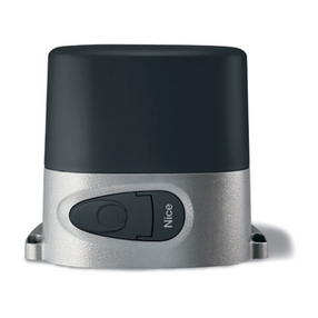
5.1 - GEARMOTOR INSTALLATION ON RACKLESS GATES
Ifthesurfaceitistorestonalreadyexists,thegearmotormustbemount-
eddirectlyontothatsurfaceusingappropriatemeans,e.g.expansion
bolts.Otherwise,proceedasfollows:
01. Digasuitablysizedfoundationpitinrelationtothepositionofthe
installation;seethedimensionsgivening.2;
02. Prepare one or two ducts for routing the cables as indicated in g.5.
N.B.: make sure the tubes are 50 cm longer than the nominal rating;
03. Assemble the two anchoring devices onto the foundation plate, plac-
ingonenutunderandoneovertheplate;thenutundertheplate
must be tightened as in g.6 so that the threaded section protrudes
byaround36mmabovetheplate;
04. Before pouring the concrete, prepare the foundation plate with its
stampedside(sprocketside)towardsthegateandfollowingtheindi-
cations of g.7;thenroutethecableductingthroughthehole;
05. Now pour the concrete and settle the plate as shown in point 04,
makingsureitisparalleltothegateandperfectlylevel(g.8).Wait
fortheconcretetosetfully;
06. Whentheconcretehassetsufciently(afterafewdays),removethe
2uppermostnutsasthesearenolongerrequired;
07. Shortenthecableductingbyaround30/40mm;
08. Remove the nut cover on the gearmotor(g.9);
09. Placethegearmotorontheplate,makingsureitisperfectlyparallel
to the gate, then hand tighten the 2 provided locknuts and washers
(g.10).Fullytightendownthenuts;
10. Manuallyreleasethegearmotor,asexplainedin11.3-Usageguide;
11. Movethegatetothefullyopenpositionbyhand,andpositionthe
rstsectionoftherackabovethegearmotor'ssprocket.Therack
mustprotrudeoverthesprocket'saxisbytheamountshowning.
11 (motortotheleft)org.12(motortotheright);i.e.,theamount
requiredforthestopbrackets;
Important!–Leavea1mmgapbetweentherack(allsections)and
sprocket (g.13),sothattheweightofthegateisnotbornebythemotor.
12. Nowmounttheothersectionsofrackonebyone:tokeeptherack
levelwiththesprocket,simplytracethemountingholewhentheslot
isinlinewiththeaxisofthesprocket(g.14).Repeatforallmounting
positions;
13. Afteryouhaveinstalledthelastsectionofrack,cutoffanyexcess
length;therackmustnotprotrudebeyondthegateitself;
14. Openandclosethegatebyhandafewtimestocheckthattherack
runssmoothlyoverthesprocket;
15. Roughlypositionthetwolimitswitchbrackets[A]ontherack(g.
15),movethegatebyhandandsecuretheminplace.
16. Securethelimitswitchbrackets:
a)movethegatebyhandtotheopenposition,stoppingatleast2-3
cmbeforethemechanicalstop.
b) slide the limit switch bracket along the rack in the opening direc-
tionuntilthelimitswitchtrips.Nowmovethebracketatleast2cm
furtherandlockitontotherackwiththeprovidedcaptivebolts.
c)repeattheoperationwiththeclosedpositionlimitswitch.
17. Manuallylockthegearmotor,asexplainedin11.3-Usageguide;
Youcannowmaketheelectricalhookup,seechapter6.
5.2 - GEARMOTOR INSTALLATION ON GATES WITH PRE-
EXISTING RACK
Ifthesurfaceitistorestonalreadyexists,thegearmotormustbemount-
eddirectlyontothatsurfaceusingappropriatemeans,e.g.expansion
bolts.Otherwise,proceedasfollows:
Warnings
–Beforemountingthegearmotor,checkthattheexistingrackiscompat-
iblewiththesprocket'soveralldimensions,seeg.16.
–Checkthattherack'spitchisabout12mm.
01. Digasuitablysizedfoundationpitinrelationtothepositionofthe
installation;seethedimensionsgivening.2;Important! – The
foundationplatemustbelocated77mmawayfromtherack.
02. Prepare one or two ducts for routing the cables as indicated in g.5.
N.B.: make sure the tubes are 50 cm longer than the nominal rating;
03. Assemble the two anchoring devices onto the foundation plate, plac-
ingonenutunderandoneovertheplate;thenutundertheplate
must be tightened as in g.6 so that the threaded section protrudes
abovetheplatebyaround36mm;
04. Before pouring the concrete, prepare the foundation plate with its
stampedside(sprocketside)towardsthegateandfollowingtheindi-
cations of g.17;thenroutethecableductingthroughthehole;
05. Now pour the concrete and settle the plate as shown in point 04,
makingsureitisparalleltothegateandperfectlylevel(g.8).Wait
fortheconcretetosetfully;
06. Whentheconcretehassetsufciently(afterafewdays),removethe
2uppermostnutsasthesearenolongerrequired;
07. Shortenthecableductingbyaround30/40mm;
08. Remove the nut cover on the gearmotor(g.9);
09. Place the gearmotor onto the foundation plate to facilitate its insertion
undertherack(g.18).Handtightenthe2locknutswiththeirwash-
ers;
10. Ifnecessary,adjusttheheightofthegearmotor(maximumadjust-
ment10mm),withthe4captivebolts(g.19).Important! – Leave
at least a 1 mm gap between the rack and sprocket, so that the
weightofthegateisnotbornebythemotor.
We advise mounting the gearmotor without the captive bolts, so that
itismorestablysupportedbytheplate;
11. Checkthatthegearmotorisperfectlyparallelwiththegate,thenfully
tightendownthe2locknutstoxittothefoundationplate;
12. Manuallyreleasethegearmotor,asexplainedin11.3-Usageguide;
13. Openandclosethegatebyhandafewtimestocheckthattherack
runssmoothlyoverthesprocket;
14. Fit the limit switch brackets [A](g.15):
a)movethegatebyhandtotheopenposition,stoppingatleast2-3
cmbeforethemechanicalstop.
b) slide the limit switch bracket along the rack in the opening direc-
tionuntilthelimitswitchtrips.Nowmovethebracketatleast2cm
furtherandlockitontotherackwiththeprovidedcaptivebolts.
c)repeattheoperationwiththeclosedpositionlimitswitch.
15. Manuallylockthegearmotor,asexplainedin11.3-Usageguide;
Youcannowmaketheelectricalhookup,seeSTEP6.
