English
English – 3
KNOWLEDGE OF THE PRODUCT AND PREPARATION FOR INSTALLATION
––– STEP 3 –––
3.1 - CHECK SUITABILITY OF GATE TO BE AUTOMATED
AND OF THE ENVIRONMENT
•Ensurethatthemechanicalstructureofthegateissuitableforauto-
mationandcomplieswithlocalstandards.Toverifythis,refertothe
technicaldataonthelabelofthegate.Important - This product cannot
automateagatethatisnotalreadysecureandefcient;moreover,it
cannotresolvedefectscausedbyimproperinstallationofthegateor
fromitspoormaintenance.
•Manuallymovethegateleavesinthetwodirections(open/closed)and
make sure that the movement takes place with a constant friction at
everypointinitscourse(thereshouldbenopointsthatrequiremore
effortnorless).
•Ifthereisanaccessdoorinthegate,orwithintherangeofmovement
of the gate, make sure that it does not obstruct normal travel and, if
necessary,provideanappropriateinterlocksystem.
•Makesurethatthegateisnotonaslope,i.e.thattheleafdoesnot
movebyitselfwhenitismanuallymovedtoanyposition.
•Ensurethattheenvironmentinwhichthegearmotoristobeinstalled
hassufcientspacetobeabletoperformthemanualmanoeuvreof
releasingthegearmotor.
•Makesurethatthesurfacesselectedfortheinstallationofthedevic-
es,arestrongandcanensureastableattachment;forthephotocells,
chooseaatsurfacethatcanensureacorrectalignmentofthepair(Tx
andRx).
•Ensurethatalldevicestobeinstalledareinashelteredlocationand
protectedagainsttheriskofaccidentalimpact.
•Ensure that the area surrounding the automation does not contain
deviceswhichproductpersistentradiointerference.Thesecandisturb
anddistortsystemfunctionality.
•Checkthedimensionallimitsbyreferringtog.2.
•Checkthatthereissufcientspace,evenwiththegateintheopenposi-
tion(g.3).
•Check,accordingtotheopeningangleoftheleaves,thatyoucanmeet
the limits in g.4and the graph in g.5).
•Therearsupportbracketcanbemountedinvariousways(g.10):the
amount“C” mayvarybetween53mmand176mm.Usuallyitisaround
150mm.
•Theamount“D”isavaluethatyoucaneasilymeasureonthegate.
•Theamount“A”isthesumof“C”and“D”.
•Basedonthevalueof“A”,andthegateopeningangle,inGraph 2 you
canobtainthevalueof“B”.Forexample:if“A”is150mmandthegate
openingangleis100°,thevalueof“B”isintheregionof150mm.
We advise you to choose “A” and “B” values which are similar
to one another. By doing this, you are assured of a regular leave
movement, and minor stress to the gearmotor.
3.2 - PRODUCT APPLICATION LIMITS
Before proceeding with installation perform the following checks in the
suggested order and check their compliance with both the data in this
paragraphandthetechnicaldatainthechapter“Producttechnicalspeci-
cations”:
1- Check that the gate leaves have dimensions and weights which fall
withinthefollowinglimits:
- maximum length 2.2 m
- maximum weight 250 kg
- opening angle of up to 120°
Theshapeofthegateandtheclimaticconditions(forexampleastrong
wind)canreducethesemaximumvalues.Inthiscase,itisnecessaryto
measure the torque required to move the leaves in the harshest condi-
tions,andcompareitwiththedatareportedinthetechnicalspecica-
tions.
2- Checkthemeasurementsofthetotalsizeofthegearmotor(g.2).
Note - These measurements also serve as a reference to calculate
the space that the foundation excavation will require for the passage
of the raceways for the electrical cables.
3- Checkthattheestimatedmaximumnumberofdailycycles(para-
graph3.2.1)iscompatiblewiththeintendeduse.
4- Checkthattheestimateddurabilityiscompatiblewiththeintended
use(seeparagraph3.3).
5- Makesureyoucancomplywithallthelimitations,conditionsand
warningsinthismanual.
NOTE TO MANUAL
•Thismanualdescribes how to implement a complete and opti-
malautomation,likethatshowning.6,usingalltheMhouse
devices which form part of the automation system known as
“WG2W”. Some devices and accessories mentioned in this man-
ual are optional and may not be present in the kit. For a com-
plete overview, see the Mhouse product catalogue or visit www.
niceforyou.com.
•Thismanualisdesignedasastep-by-step guide. Therefore, for
the safety and ease of assembly and programming work, we
advice you to carry out all the operations described in the same
order in which they are presented.
––– STEP 2 –––
2.1 - PRODUCT DESCRIPTION AND INTENDED USE
Thedevicesinthiskit,plusotheraccessories(someoptionalandsome
notincluded),togetherformtheautomationsystemcalled“WS2W”,
designedforautomationofahingedgatefor“residential”use.All uses
other than the intended use described and use in environmental
conditions other than those described in this manual should be
consideredimproperandforbidden!
The main part of the automation consists of a control unit and two elec-
tromechanicalgearmotors.Eachgearmotorisprovidedwitha24Vdirect
currentmotorandareductionunitwithwormscrews;itisequippedwith
amechanicalreleaseandkeywhichallowsyoutomanuallymovethe
gateintheeventofalackofpowersupply.
The command control unit manages the operation of all of the automa-
tion, and is made up of an electronic board and an integrated radio receiv-
er,toreceivecommandssentbytheuserviathetransmitter.Itcanstore
upto256GTX4transmitters,andupto20wirelessdevices.
TheinnovativeMhousePower&FreeSystemallowsthecontrolunitto
directthePH100WphotocellsandtheFL100Washingindicator,without
wiredconnections.Howeveritispossibletoconnectotherdevices,using
a single cable with two electrical conductors, on the inputs assigned to
opening(Open)andstopping(Stop).Thecontrolunitcanbepoweredby
axedelectricalnetwork(230V)or,alternatively,bysolarenergyviathe
PFsolarpowersystemfrom the Mhouse line.
Ifpoweredfromthegrid,itcanhostabufferbattery(mod.PR1,option-
alaccessory)whichensuresthattheautomationcanexecutecertain
manoeuvres,duringthehoursfollowingalossofpower(electricalblack-
out).Itishoweveralwayspossibletomovethegatemanually,byrst
releasingthegearmotorusingtheappropriatekey(seechapter11.3-
Usageguide).
2.2 - DEVICES REQUIRED TO CREATE A FULL SYSTEM
The g.1showsallthedevicesrequiredtocreateafullsystem,suchas
that shown in g.6.
Thedevicesshowning.1are:
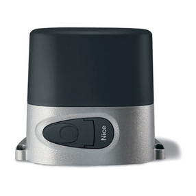
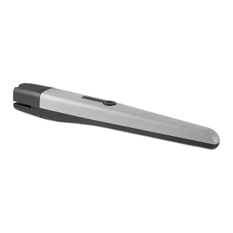
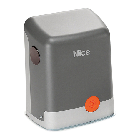
A- 2 electromechanical WS1SK gearmotors, complete with mounting
brackets
B-3releasekeys
C-1pairofPH100Wphotocells(madeupofaTXandanRX)
D- 2 GTX4 radio transmitters
E-1FL100Washingindicator
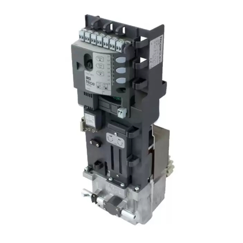
F- 1 CL2W command control unit
G- Metal hardware
Note:
- Some devices and accessories mentioned in this manual are option-
alandmaynotbepresentinthekit.Foracompleteoverview,seethe
Mhouseproductcatalogueorvisitwww.niceforyou.com.
- The end stops are not included in the kit and do not form part of the
Mhouseproductrange.
