DESIGNED TO WORK WITH MOST BRANDS OF GATE AND DOOR OPENERS
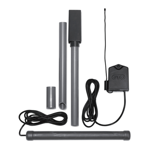
The RB709U-NB digital receiver is a wireless radio control designed for use with automated
gate openers and garage door openers. The receiver has two channels for receiving signals
from two activation devices; i.e. transmitters, multi-button transmitters, wireless keypads, etc.
Consider the following when mounting the receiver:
• Standard receiver cable length is 10 feet (3.05 m).
• For exterior applications run the cable through PVC conduit to protect it
from damage.
• DO NOT run cable in conduit containing
AC wiring.
• The receiver range can vary from 50 to 100 feet (15.2 to 30.5 m)
depending upon weather, topography and external interference.
NOTE: Do not mount upside down in exterior applications.
Channel 1 (To COM)
Channel 1 (To N/O Contact)
Channel 2 (To COM)
Channel 2 (To N/O Contact)
2nd GATE OPERATOR or DOOR OPENER
1st GATE OPERATOR or DOOR OPENER
8 to 24 VOLT AC/DC
POWER SUPPLY
RED WIRE to POSITIVE
BLACK WIRE to NEGATIVE
RED
BLACK
GREEN
BLUE
BROWN
YELLOW
Programming transmitter(s) or other access devices to RB709U-NB receiver:
• Press and hold the transmitter (device) button to be learned.
• Press the ‘LEARN CH1’ (or ‘LEARN CH2’) button on the RB-
709U-NB receiver for 1-2 seconds or until the red LED turns on,
then release the button.
• Note: When the correct code is received and the corresponding
relay output is activated, the red LED will turn on.
Check operation after programming:
• Press Transmitter (device) button, #1 - RED LED blinks once to conrm.
• Press Transmitter (device) button, #2 - RED LED blinks twice to conrm.
POWER
ON OFF
K1
06
D1
C2
C15
LED3
D15
R20
IC4
D16
D13
D14
K2
BATT- BATT+
EDGE
COM
LOCK+
LOCK - M_BLK
M_RED
VAR2
GRN
VAR3
VAR3
VAR1
VAR4
VAR5
PF1
VAR6
WHT
CYCLE
EXIT
SAFETY
COM
CHGR
CHGR
POWER
LED3
D15
R20
IC4
D16
D13
D14
K2
BATT- BATT+
EDGE
COM
LOCK+
LOCK - M_BLK
M_RED
GRN
VAR3
VAR3
VAR1
VAR4
VAR5
VAR6
CYCLE
EXIT
SAFETY
COM
CHGR
CHGR
BLUE
RED
BROWN
BLACK
YELLOW
GREEN
VAR5
VAR6
K1
PF1
K2
BATT +
BATT –
K3
K4
VAR4
VAR3
VAR2
VAR1
MIN MAX OFF
≤JP1
REMOVE JUMPER FOR
PUSH TO OPEN OPTION
120
SEC.
GTO Inc. Tallahassee, FL
R4722
STALL FORCE
OPEN < JOG > CLOSE
PWR. SET
LIMIT
1st OPR.
2nd OPR.
STATUS
AUTO CLOSE
SFTY.
EXIT
CYCLE
EDGE
SENSOR
COMMON
LOCK+
LOCK–
WHT
GRN
RED
BLK
WHT
GRN
SECOND OPR.FIRST OPR.
RED
BLK
14 VAC
OR
SOLAR
ON OFF
BLUE
RED
BROWN
BLACK
YELLOW
GREEN
MM271 Wiring Diagram
MM272 and PRO-SW2000XLS
Series Wiring Diagram
NOTE: This diagram also works for MM262, MM362
and MM462.
NOTE: This diagram also works with MM260.
Mounting the Receiver
Connect Receiver to Relay Inputs and Power
Programming the Receiver
Wiring Receiver to MM271 and MM272 Operators
GREEN WIRE
BLUE WIRE
BLACK
RED
BROWN WIRE
YELLOW WIRE
Control Board
Wiring Receiver to MM371, MM372, MM571 & MM572 Operators
2 3

