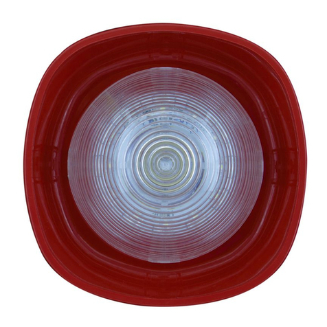
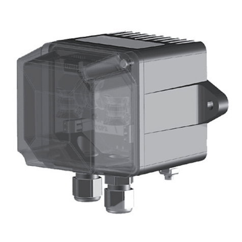
Eaton Activeline GH5 User manual

GH5 Activeline Beacon Technical Manual
Eaton MEDC technical manual

2GH5 ACTIVELINE BEACON TECHNICAL MANUAL TMF0075.A www.eaton.com
DISCLAIMER OF WARRANTIES AND LIMITATION OF LIABILITY
The information, recommendations, descriptions and safety notations in this document are based on Eaton Corporation’s
(“Eaton”) experience and judgment and may not cover all contingencies. If further information is required, an Eaton sales
office should be consulted. Sale of the product shown in this literature is subject to the terms and conditions outlined in
appropriate Eaton selling policies or other contractual agreement between Eaton and the purchaser.
THERE ARE NO UNDERSTANDINGS, AGREEMENTS, WARRANTIES, EXPRESSED OR IMPLIED, INCLUDING
WARRANTIES OF FITNESS FOR A PARTICULAR PURPOSE OR MERCHANTABILITY, OTHER THAN THOSE
SPECIFICALLY SET OUT IN ANY EXISTING CONTRACT BETWEEN THE PARTIES. ANY SUCH CONTRACT STATES THE
ENTIRE OBLIGATION OF EATON. THE CONTENTS OF THIS DOCUMENT SHALL NOT BECOME PART OF OR MODIFY
ANY CONTRACT BETWEEN THE PARTIES.
In no event will Eaton be responsible to the purchaser or user in contract, in tort (including negligence), strict liability or
other-wise for any special, indirect, incidental or consequential damage or loss whatsoever, including but not limited to
damage or loss of use of equipment, plant or power system, cost of capital, loss of power, additional expenses in the
use of existing power facilities, or claims against the purchaser or user by its customers resulting from the use of the
information, recommendations and descriptions contained herein. The information contained in this manual is subject to
change without notice.
FRANCAIS
Les informations, recommandations, descriptions et indications de sécurité dans ce document sont basées sur l’expérience et le jugement
d’Eaton Corporation (“Eaton”) et peuvent ne pas couvrir toutes les éventualités. Si des informations supplémentaires sont nécessaires,
consultez un bureau de vente Eaton. La vente du produit décrit dans ce document est soumise aux conditions générales décrites dans les
politiques commerciales d’Eaton ou l’accord contractuel entre Eaton et l’acheteur.
IL N’Y A PAS ENTENTE, ACCORD, GARANTIE, EXPLICITE OU IMPLICITE, Y COMPRIS DE GARANTIE D’ADAPTATION À UN USAGE
PARTICULIER OU DE QUALITÉ MARCHANDE, AUTRES QUE CEUX SPECIFIÉS DANS TOUT CONTRAT EXISTANT ENTRE LES PARTIES.
UN TEL CONTRAT DÉCRIT L’ENGAGEMENT COMPLET D’EATON. LE CONTENU DE CE DOCUMENT NE DOIT PAS DEVENIR PARTIE OU
MODIFIER TOUT CONTRAT ENTRE LES PARTIES.
En aucun cas Eaton ne saura être tenu responsable par l’acheteur ou par l’utilisateur partie au contrat, à tort (négligence comprise) d’une
responsabilité stricte ni de tout autre dommage ou perte particulier, indirect, accidentel ou conséquentiel, de quelque type que ce soit,
y compris sans y être limité tout dommage ou perte d’utilisation de l’équipement, de l’usine ou du système d’alimentation, du coût de
capital, de la perte de puissance, des dépenses supplémentaires engendrées par l’utilisation de systèmes d’alimentation existants, ni de
toute réclamation par des clients à l’acheteur ou à l’utilisateur résultant de l’utilisation des présentes informations, recommandations et
descriptions.. Les informations contenues dans ce manuel sont sujettes à modification sans préavis.
3
Table of Contents
GH5 ACTIVELINE BEACON TECHNICAL MANUAL TMF0075.A www.eaton.com
Table of contents
Multicolour Light GH5.............................................................................4
CE symbol ......................................................................................4
Application......................................................................................4
Construction. . . . . . . . . . . . . . . . . . . . . . . . . . . . . . . . . . . . . . . . . . . . . . . . . . . . . . . . . . . . . . . . . . . . . . . . . . . . . . . . . . . . .4
Mounting .......................................................................................4
Care and maintenance ............................................................................4
X Protection against mechanical impact .............................................................4
Notes on cable gland and cable entry ................................................................4
Recycling .......................................................................................5
Connection......................................................................................5
For Multicolour Lights with operating voltage 230 VAC ..................................................5
For Multicolour Lights with operating voltage 24 VDC ...................................................5
Settings ........................................................................................5
Setting the operating modes (example: colour red) ....................................................6
Operating modes.................................................................................6
Continuous light .................................................................................6
Example ........................................................................................6
Blink ..........................................................................................6
Flash ..........................................................................................6
Technical specications............................................................................7
User information .................................................................................8

4
GH5 Activeline Beacon Technical Manual
GH5 ACTIVELINE BEACON TECHNICAL MANUAL TMF0075.A www.eaton.com
CE symbol
We hereby declare this product is in compliance with the Essential Health and Safety Requirements of
ATEX Directive 2014/34/EU,
EMC Directive 2014/30/EU,
Low Voltage Directive 2014/35/EU and RoHS Directive 2011/65/EU.
The appropriate standards, technical regulations und specifications you can take from the attached conformity declaration
and the conformity declarations on our Website.
ø 8,5
26
135
185 103 120
268
300
315
[mm]
Multicolour Light GH5 Dimensions
Application
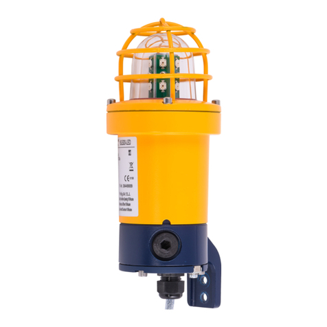
The ActiveLine Multicolour Light GH5 is designed as a fixed device of equipment group II category 3 for use in areas that
can rarely and at short notice be endangered by an explosive atmosphere. The Multicolour Light GH5 is constructed for
use in zone 2 and 22. The light is an optical signalling de vice for universal use. The possible signalling colours red, yellow,
green, blue and white serve many different signalling functions. The different signalling colours are generated in one
single light element. Every colour allows presetting one of the operating modes: continuous light, signalling light or flash
light. The light is generated by light-emitting diodes.
Construction
The plastic enclosure and the cap consist of impact resistant polycarbonate. The metal bracket is intended for wall
mounting.
Mounting
The device may be placed in any position. The mounting angle can be rotated 90°, requiring you to loosen the 4 hexagon
socket screws using a 4 mm Allen key, rotating the mounting angle in the desired position, inserting the screws and
tightening them. The device is fastened with 2 screws (ø 6...8 mm) on the wall/ceiling.
Care and maintenance
The strobe light contains no serviceable parts. The requirements of EN 60079-17 regarding the regular control of the
explosion protection must be applied.
X Protection against mechanical impact
The device should be positioned in such a way that mechanical damage, e.g. due to falling parts or lateral impact is
prevented.
Notes on cable gland and cable entry
1. Ambient operating temperature: Ta: -20°C to +50°C
2. Thread diameter: Ø M20 x 1.5
3. Housing degree of protection: IP 66
4. Type of protection: Ex e II
5. Use only suited tools for installing the cable glands.
6. The cable gland is suited for permanent wiring only.
7. In case of factory fitted cable glands the attached operating instructions have to be considered.

5
GH5 Activeline Beacon Technical Manual
GH5 ACTIVELINE BEACON TECHNICAL MANUAL TMF0075.A www.eaton.com
Recycling
Complete disposal of the device is done as electronics waste. When dismantling the device, the plastic, metal and
electronic components must be disposed of separately.
Connection
Loosen the two cover screws with an Allen key size 4 and remove the cover. Before connecting the Light make sure the
conductors of the power cable are dead (no voltage). The power cable is fed through the cable gland to the interior of
the enclosure and is fixed with the screw part of the cable gland. Inside the en - closure there are the terminals on the
printed circuit board. After having set up the connection, please fix the cover to the housing and tighten the screws with
a torque of 0.9 … 1.1 Nm.
For Multicolour Lights with operating voltage 230 VAC
Connect the neutral connector to the terminal marked „N“. Connect the white, blue, red, yellow and green operating
voltage conductors to the accordingly marked terminals.
Terminals with 230 VAC
gn ye rd bl wh N
230V
AC
For Multicolour Lights with operating voltage 24 VDC
Connect the 0 V or the negative cable conductor to the terminal designated with „GND“. Connect the cable conductors
with positive voltage corresponding to the colours white, blue, red, yellow, and green to the accordingly designated
terminals.
Terminals with 24 VDC
gn ye rd bl wh GND
24 V
DC
As far as the set up of the Multicolour Light by means of the slide switches has not taken place yet, go to chapter
„Settings“. Otherwise fix the cover to the housing and tighten the screws with a torque of 0.9 … 1.1 Nm.
Settings
Before making the setting, make sure the Multicolour Light is disconnected (no voltage).
When the enclosure is open, (a) circuit board(s) are visible. On one side are the terminals described under
„Connection“ and on the other side is a block of 10 slide switches marked 1…10, for setting the operating mode of
the individual colours (white, blue, red, yellow, green).
Slide switch (slider drawn
in white, as-shipped state)
12345678910
wh bl rd ye gn
white blue red yellow green

6
GH5 Activeline Beacon Technical Manual
GH5 ACTIVELINE BEACON TECHNICAL MANUAL TMF0075.A www.eaton.com
Setting the operating modes (example: colour red)
rd
rd
rd
rd
56
56
56
56
Colour is continuously lit when activated
Colour flashes when activated
Colour blinks when activated
Colour is unlit, independent of whether signal is activated or not.
Operating modes
Each colour may be operated independently of the other colours in the operating modes continuous light, blink light or
flash light. The change of colour always takes place in the order green-yellow-red-blue-white.
Continuous light
When using only one colour, this colour is turned on continuously. When using more than one colour in the operating
mode „continuous light“ each colour is turned on for 990 ms. Then the changeover to the next driven colour takes place.
Example
The colours green, red and white are in use.
grün / green / vert / verde rot / red / rouge / rojo weiß / white / blanc / blanco grün / green / vert / verde
990 ms
Blink
When using one colour, it will be lit for 220 ms and turned off for 275 ms.
275 ms
220 ms
When using several colours, the colour blinks twice, being lit for 220 ms and turned off for 275 ms.
1265 ms
Flash
When using one colour, it will be lit for 55 ms and turned off for 440 ms.
55 ms
440 ms
When using several colours, the colour flashes 4 times, being lit for 55 ms and turned off for 440 ms.
2420 ms

7
GH5 Activeline Beacon Technical Manual
GH5 ACTIVELINE BEACON TECHNICAL MANUAL TMF0075.A www.eaton.com
Technical specications
Storage and transport temperature -20°C…+70°C
Enclosure Polycarbonate
Cap Polycarbonate
Cable gland M20 x 1.5
Clamp capacity of terminals 2.5 mm2
Operating position any position
Weight appr. 1.4 kg
Operating modes
Continuous light
one colour: the colour is continuously on
more than one colour: 990 ms turn-on time per colour
Blink light
one colour: 220 ms turn-on time, 275 ms turn-off time
more than one colour: blinks 2 times per colour
Flash light
one colour: 55 ms turn-on time, 440 ms turn-off time
more than one colour: flashes 4 times per colour
Change of colour always in the order green-yellow-red-blue-white
Version with AC Voltage
Operating voltage (Voltage between
colour terminals and terminal „N“) 230 VAC, 50…60 Hz
Current consumption at 230 VAC,
colour white on < 50 mA
Power consumption < 12 W
Insulation class II
Overvoltage category II
Version with DC voltage
Operating voltage (voltage between
colour terminal and terminal „GND“) 24 VDC
Tolerance of operating voltage ± 20%
Current consumption colour white on < 135 mA
Power consumption
at rated operating voltage < 4 W
Insulation class III / II
Marking on name plate
FHF Funke + Huster Fernsig GmbH D-45478 Mülheim a.d. Ruhr
Type: GH5 FHF 10 ATEX 0004 X*) FHF 10 ATEX 0006 X**)
II 3 G Ex nR IIC T6 Gc
II 3 D Ex tc IIIC T85°C Dc
-20°C ≤ Ta ≤ +50°C
Ui = **)........ IP66
Do not open while under power.
After de-energizing, delay X minutes before opening.
Potential electrostatic charging hazard - see instructions.
P/N: ..........................
F-No.: .......................
Month/Year/Tested by
*) Mechanically protected installation
**) Input voltage depending on version.

8
GH5 Activeline Beacon Technical Manual
GH5 ACTIVELINE BEACON TECHNICAL MANUAL TMF0075.A www.eaton.com
User information
This equipment is an explosionproof device designed for use in areas that are usually not expected to be exposed to
an explosive atmosphere or that are endangered rarely and for a short time by an explosive atmosphere. Designed
as a device of group II, category 3 it can be used in zone 2 and 22. Please note the following warnings and safety
information.
1. Only a trained and skilled technical specialist may connect and mount the device, while taking into consideration the
category of protection and following the stipulated installation regulations.
2. This device is constructed in insulation class III or II and must only be connected to and operated at the stipulated
voltage. Please pay attention to the polarity information. For insulation class II, the constructor must install the
appliance in such a way as to make sure it still fulfils the requirements of this insulation class after installation.
3. It is not permissible to operate the device in a damaged state.
4. While operating the device in business or industry facilities, the legally or otherwise required precautions against
accidents resulting from the use of electrical systems and devices must be taken.
5. The device may be operated solely under the stated ambient conditions. Adverse ambient conditions may lead to the
device being damaged, thus representing a risk to the users life. Such adverse conditions may be:
• too high humidity of air (>90% rel., condensing)
• dust deposits
• combustible gases, vapours, solvents not covered by the protection category of the device
• too high ambient temperatures (>50°C), e.g. caused by intensive sunlight
6. Repairs may be carried out by the manufacturer or by a person appointed by the manufacturer followed by a renewed
product conformity inspection.
7. The ambient temperature may neither exceed nor fall below the temperature range given fort he device. Inadmissable
radiant energy and convection in the vicinity of the device have to be prevented.
8. Warning! At the devices there is hazard of ignition by electrostatic discharges. Charging e.g. by friction or during
cleaning has to be avoided. The assembly has to be carried out in a way that a hazardous electrostatic charging e.g.
by pneumatic delivery will be avoided.
9. Only the cable glands required by the manufacturer may be used.
10. Make sure the device and the wiring are dis - connected from the power supply upon connecting or disconnecting
the wires. After de-energizing delay 5 minutes before opening.
In case of disregard of the above, the explosion protection of the device is no longer guaranteed. In this case, the device
represents a danger to the lives of personnel and may cause the ignition of a hazardous atmosphere.

9
GH5 Activeline Beacon Technical Manual
GH5 ACTIVELINE BEACON TECHNICAL MANUAL TMF0075.A www.eaton.com
Inhaltsverzeichnis
ehrfarbenleuchte GH5 ............................................................................10
CE-Zeichen .....................................................................................10
Anwendung ....................................................................................10
Aufbau ........................................................................................10
Montage .......................................................................................10
Wartung und Pege..............................................................................10
X Schutz vor hohen mechanischen Einwirkungen .....................................................10
Hinweise zur Kabel- und Leitungseinführung.........................................................10
Recycling ......................................................................................11
Anschluss ......................................................................................11
Für Mehrfarbenleuchten mit Betriebsspannung 230 VAC ................................................11
Für Mehrfarbenleuchten mit Betriebsspannung 24 VDC .................................................11
Einstellung .....................................................................................11
Einstellung der Betriebsarten (am Beispiel der Farbe rot)...............................................12
Betriebsarten ...................................................................................12
Dauerlicht ......................................................................................12
Beispiel ........................................................................................12
Blinken ........................................................................................12
Blitzen.........................................................................................12
Technische Daten ................................................................................13
Benutzerinformationen ...........................................................................14

10
GH5 Activeline Beacon Technical Manual
GH5 ACTIVELINE BEACON TECHNICAL MANUAL TMF0075.A www.eaton.com
ø 8,5
26
135
185 103 120
268
300
315
[mm]
Mehrfarbenleuchte GH5 Maßbild
CE-Zeichen
Wir erklären hiermit, dass sich dieses Produkt in Übereinstimmung mit den grundlegenden Sicherheits- und
Gesundheitsanforderungen
der ATEX-Richtlinie 2014/34/EU,
der EMV-Richtlinie 2014/30/EU,
der Niederspannungsrichtlinie 2014/35/EU
und der RoHS-Richtlinie 2011/65/EU befindet.
Die entsprechenden Normen, technischen Regeln und Spezifikationen entnehmen Sie bitte der beigefügten
Konformitätserklärung und den Konformitätserklärungen auf unserer Website.
Anwendung
Die ActiveLine Mehrfarbenleuchte GH5 ist als ortsfestes Gerät der Gerätegruppe II Kategorie 3 ausgeführt. Sie ist geeignet
für den Einsatz in Bereichen, die selten und kurzzeitig durch explosionsfähige Atmosphäre gefährdet werden können. Die
Mehr - farbenleuchte GH5 ist in der Zone 2 und 22 einsetzbar. Sie ist ein universell einsetzbarer optischer Signalgeber, der
mit den möglichen Signalfarben rot, gelb, grün, blau und weiß eine Vielzahl von Signalisierungsaufgaben erfüllen kann. Die
verschiedenen Signal far ben werden in einem einzigen Leucht element angezeigt. Jede Far be kann durch Voreinstellung in
die Betriebsarten Dauerlicht, Blinken oder Blitzen gebracht werden. Die Licht - erzeugung geschieht mit Leucht dioden.
Aufbau
Das Kunststoffgehäuse und die Kalotte bestehen aus schlag - festem Polycarbonat. Zur Wand befestigung dient ein Metall - bügel.
Montage
Das Gerät darf in beliebiger Lage angebracht werden.Der Montagewinkel kann um 90° gedreht werden, dazu müssen Sie mit
einem 4 mm großen Sechskantschlüssel die 4 Innensechskantschrauben lösen, den Montagewinkel in die gewünschte Position
drehen, die Schrauben einsetzen und festziehen. Das Gerät wird mit 2 Schrauben (ø 6...8 mm) an der Wand/Decke befestigt.
Wartung und Pflege
Die Blitzleuchte enthält keine zu wartenden Teile. Die Vor gaben der EN 60079-17 hinsichtlich der regelmäßigen
Überprüfung des Explosionsschutzes sind einzuhalten.
X Schutz vor hohen mechanischen Einwirkungen
Das Gerät ist so zu platzieren, dass eine mechanische Be - schädigung, z.B. durch herab fallende Teile oder seit liche
Stöße verhindert ist.
Hinweise zur Kabel- und Leitungseinführung
1. Betriebsumgebungstemperatur: Ta: -20°C bis +50°C
2. Gewindedurchmesser: Ø M20 x 1,5
3. Gehäuseschutzart: IP 66
4. Zündschutzart: Ex e II
5. Zur Montage der KLE sind nur geeignete Werkzeuge zulässig!
6. Der Kabelanschluss ist nur für fest verlegte Leitungen geeignet.
7. Bei den werkseitig bestückten KLE ist die beigefügte Betriebsanleitung zu beachten.

11
GH5 Activeline Beacon Technical Manual
GH5 ACTIVELINE BEACON TECHNICAL MANUAL TMF0075.A www.eaton.com
Recycling
Die Komplettentsorgung der Geräte erfolgt über den Elektronikabfall. Bei Demontage des Gerätes sind die Komponenten
Kunststoff, Metalle und Elektronik seperat zu entsorgen.
Anschluss
Lösen Sie die zwei Deckelschrauben mit einem Inbusschlüssel Größe 4 und nehmen Sie den Deckel ab. Bevor die
Leuchte angeschlossen wird, müssen die Adern des Anschlusskabels spannungsfrei geschaltet sein. Das Anschlusskabel
wird durch die Leitungseinführung ins Innere des Gehäuses geführt und mit dem Schraubteil der Leitungseinführung
fixiert. Im Inneren des Gehäuses befinden sich auf der Leiterplatte die Anschlussklemmen. Nach dem Anschluss fixieren
Sie den Deckel an das Gehäuse und drehen die Schrauben mit einem Drehmoment von 0,9 ... 1,1 Nm fest.
Für Mehrfarbenleuchten mit Betriebsspannung 230 VAC
Legen Sie den Nullleiter auf die Klemme mit der Kennzeichnung „N“. Legen Sie die den Farben weiß, blau, rot, gelb und
grün zugeordneten Leitungsadern mit Betriebsspannung auf die entsprechend gekennzeich neten Klemmen.
Anschlussklemmen bei 230 VAC
gn ye rd bl wh N
230V
AC
Für Mehrfarbenleuchten mit Betriebsspannung 24 VDC
Legen Sie die 0 V oder negative Leitungsader auf die Klemme mit der Kennzeichnung „GND“. Legen Sie die den Farben
weiß, blau, rot, gelb und grün zugeordneten Leitungsadern mit positiver Betriebsspannung auf die entsprechend
gekennzeichneten Klemmen.
Sofern die Einstellung der Mehrfarbenleuchte über die Schiebeschalter noch nicht erfolgt ist, gehen Sie zum Abschnitt
„Einstellung“. Sonst fixieren Sie den Deckel an das Gehäuse und drehen die Schrauben mit einem Drehmoment von
0,9…1,1 Nm fest.
Anschlussklemmen bei 24 VDC
gn ye rd bl wh GND
24 V
DC
Einstellung
Bevor die Einstellung vorgenommen wird, ist die Mehrfarbenleuchte spannungsfrei zu schalten.
Bei geöffnetem Gehäuse sind auf der einen Seite der Leiterplatte(n) die unter „Anschluss“ beschriebenen
Anschlussklemmen und auf der anderen Seite ein Block von 10 Schiebeschaltern mit der Kennzeichnung 1…10 zur
Einstellung der Betriebsart der einzelnen Farben (weiß, blau, rot, gelb, grün).
Schiebeschalter (Schiebeschalter
weiß gezeichnet, Lieferzustand
12345678910
wh bl rd ye gn
wh=weiß bl=blau rd=rot ye=gelb gn=grün

12
GH5 Activeline Beacon Technical Manual
GH5 ACTIVELINE BEACON TECHNICAL MANUAL TMF0075.A www.eaton.com
Einstellung der Betriebsarten (am Beispiel der Farbe rot)
rd
rd
rd
rd
56
56
56
56
Farbe leuchtet dauernd bei Ansteuerung
Farbe blitzt bei Ansteuerung
Farbe blinkt bei Ansteuerung
Farbe ist aus, unabhängig vonder Ansteuerung
Betriebsarten
Jede Farbe kann unabhängig von den anderen Farben in den Betriebsarten Dauerlicht, Blinken und Blitzen betrieben
werden. Farbwechsel erfolgen immer in der Reihenfolge grün-gelb-rot-blau-weiß.
Dauerlicht
Bei Ansteuerung nur einer Farbe ist diese Farbe dauernd eingeschaltet. Bei der Ansteuerung mehrerer Farben in
der Betriebsart Dauerlicht sind die Farben jeweils 990 ms eingeschaltet. Danach erfolgt der Wechsel zur nächsten
angesteuerten Farbe.
Beispiel
Die Farben grün, rot und weiß sind angesteuert.
grün / green / vert / verde rot / red / rouge / rojo weiß / white / blanc / blanco grün / green / vert / verde
990 ms
Blinken
Bei Ansteuerung einer Farbe blinkt die Farbe mit einer Einschaltzeit von 220 ms und einer Ausschaltzeitzeit von 275 ms.
275 ms
220 ms
Bei Ansteuerung mehrerer Farben blinkt die Farbe 2 mal mit einer Einschaltdauer von 220 ms und einer Ausschaltzeitzeit
von 275 ms.
1265 ms
Blitzen
Bei Ansteuerung einer Farbe blitzt die Farbe mit einer Einschaltzeit von 55 ms und einer Ausschaltzeit von 440 ms.
55 ms
440 ms
When using several colours, the colour flashes 4 times, being lit for 55 ms and turned off for 440 ms.
2420 ms

13
GH5 Activeline Beacon Technical Manual
GH5 ACTIVELINE BEACON TECHNICAL MANUAL TMF0075.A www.eaton.com
Technische Daten
Lager- und Transporttemperatur -20°C…+70°C
Gehäuse Polycarbonat
Kalotte Polycarbonat
Leitungseinführung M20 x 1,5
Klemmvermögen der Anschlussklemmen 2,5 mm2
Betriebsgebrauchslage Beliebig
Gewicht ca. 1,4 kg
Betriebsarten
Dauerlicht
eine Farbe: die Farbe ist dauernd an
mehrere Farben: 990 ms Einschaltzeit pro Farbe
Blinken:
eine Farbe: 220 ms Einschaltzeit, 275 ms Ausschaltzeit
mehrere Farben: 2 mal Blinken pro Farbe
Blitzen
eine Farbe: 55 ms Einschaltzeit, 440 ms Ausschaltzeit
mehrere Farben: 4 mal Blitzen pro Farbe
Farbwechsel Immer in der Reihenfolge grün-gelb-rot-blau-weiß
Variante für Wechselspannung
Betriebsspannung (Spannung zwischen
Farbanschlüssen und Anschluss „N“) 230 VAC, 50…60 Hz
Farbe weiß an < 50 mA
Leistungsaufnahme < 12 W
Schutzklasse II
Überspannungskategorie II
Variante für Gleichspannung
Betriebsspannung(Spannung zwischen
Farbanschlüssen und Anschluss „GND“) 24 VDC
Toleranz der Versorgungsspannung ± 20%
Stromaufnahme, Farbe weiß an < 135 mA
Leistungsaufnahme bei
Nennbetriebsspannung < 4 W
Schutzklasse III / II
Kennzeichnung auf dem Typenschild
FHF Funke + Huster Fernsig GmbH D-45478 Mülheim a.d. Ruhr
Typ: GH5 FHF 10 ATEX 0004 X*) FHF 10 ATEX 0006 X**)
II 3 G Ex nR IIC T6 Gc
II 3 D Ex tc IIIC T85°C Dc
-20°C ≤ Ta ≤ +50°C
Ui = **)........ IP66
Nicht unter Spannung öffnen.
Nach dem Abschalten X Minuten warten vor dem Öffnen.
Die gemessene Stromstiirke entspricht einer Last von 10 kΩ.
Gefahr durch elektrostatische Entladungen - siehe Betriebsanleitung.
Art.-Nr.: ......................
F-Nr.: ..........................
Prüf.: Monat/Jahr/Prüfer
*) Mechanisch geschützter Einbau
**) Eingangspannung je nach Ausführung

14
GH5 Activeline Beacon Technical Manual
GH5 ACTIVELINE BEACON TECHNICAL MANUAL TMF0075.A www.eaton.com
Benutzerinformationen
Bei diesem Gerät handelt es sich um ein explosionsgeschütztes Gerät für den Betrieb in einem Bereich, in dem nicht
damit zu rechnen ist, dass im Normalbetrieb eine explosionsfähige Atmosphäre auftritt, und wenn, dann nur selten und
kurzzeitig. Als ein Gerät der Gruppe II, Kategorie 3 ist es in der Zone 2 und 22 verwendbar. Nachstehende Warn- und
Sicherheitshinweise sind besonders zu be achten.
1. Der Anschluss und die Installation haben unter Beachtung der Zündschutzart gemäß den vorgeschriebenen
Errichtervorschriften von einem unterwiesenem Fachmann zu er folgen.
2. Dieses Gerät ist in Schutzklasse III oder II aufgebaut und darf nur an der vorgeschriebenen Spannung angeschlossen
und betrieben werden. Die Polaritätsangaben sind zu beachten. Bei Schutzklasse II hat der Errichter dafür zu sorgen,
dass durch fachgerechte Installation die Schutzklasse erhalten bleibt.
3. Im beschädigten Zustand darf das Gerät nicht be - trieben werden.
4. Bei Betrieb des Gerätes in gewerblichen Einrichtungen sind die Unfallverhütungsvorschriften der
Berufsgenossenschaften für elektrische Anlagen und Betriebsmittel zu beachten.
5. Das Gerät darf nur unter den angegebenen Umgebungsbedingungen betrieben werden. Widrige
Umgebungsbedingungen können zur Beschädigung des Gerätes führen und da mit zu einer eventuellen Gefahr für
das Leben des Benutzers. Solche widrigen Umgebungsbedingungen können sein:
• zu hohe Luftfeuchtigkeit (>90% rLF, kondensierend)
• Staubablagerungen
• brennbare Gase, Dämpfe, Lösungsmittel, die nicht durch die Zündschutzart des Gerätes abgedeckt sind
• zu hohe Umgebungstemperaturen (>50°C), z.B. durch intensive Sonneneinstrahlung
6. Instandsetzungsarbeiten dürfen nur vom Hersteller oder einer vom Hersteller beauftragten Person mit erneuter Stück
prüfung durchgeführt werden.
7. Der für das Gerät angegebene Umgebungstemperaturbereich darf während des Betriebes weder unter- noch
überschritten werden. Unzulässige Strahlungsenergie und Konvektion in der Geräteumgebung sind zu verhindern.
8. Warnung! An den Geräten besteht die Gefahr der Zündung durch elektrostatische Entladungen. Aufladungen z.B.
durch Reibung oder während der Reinigung sind zu vermeiden. Die Montage muss so erfolgen, dass eine gefährliche
elektrostatische Aufladung z. b. durch pneumatische Förderströme verhindert wird.
9. Es dürfen nur die vom Hersteller vorgeschriebenen Leitungseinführungen verwendet werden.
10. Beim Anschluss oder Abklemmen von Leitungen muss das Gerät und die Leitung spannungsfrei geschaltet sein.
Nach dem Abschalten 5 Minuten warten vor dem Öffnen.
Bei Nichtbeachtung der vorgenannten Punkte ist der Explosionsschutz des Gerätes nicht mehr gegeben. Das Gerät stellt dann
eine Gefahr für das Leben des Betreibers dar und kann die Zündung einer explosionsfähigen Atmosphäre ver ur sachen.

15
GH5 Activeline Beacon Technical Manual
GH5 ACTIVELINE BEACON TECHNICAL MANUAL TMF0075.A www.eaton.com
Table des matières
Lampe multicouleurs GH5 ........................................................................16
Marque CE .....................................................................................16
Utilisation......................................................................................16
Construction. . . . . . . . . . . . . . . . . . . . . . . . . . . . . . . . . . . . . . . . . . . . . . . . . . . . . . . . . . . . . . . . . . . . . . . . . . . . . . . . . . . .16
Montage .......................................................................................16
Entretien et maintenance .........................................................................16
X Protection contre des actions mécaniques importantes ..............................................16
Informations relatives à l’entrée de câble et de ligne ..................................................16
Recyclage ......................................................................................17
Raccordement ..................................................................................17
Pour les lampes multicouleurs avec une tension de service de 230 VAC....................................17
Pour les lampes multicouleurs avec une tension de service de 24 VDC.....................................17
Réglage........................................................................................17
Réglage des modes de service (sur l’exemple de la couleur rouge) .......................................18
Modes de service................................................................................18
Lumière continue................................................................................18
Exemple .......................................................................................18
Clignotement ...................................................................................18
Eclair .........................................................................................18
Caractéristiques techniques .......................................................................19
Informations destinées à l’utilisateur ...............................................................20

16
GH5 Activeline Beacon Technical Manual
GH5 ACTIVELINE BEACON TECHNICAL MANUAL TMF0075.A www.eaton.com
ø 8,5
26
135
185 103 120
268
300
315
[mm]
Lampe multicouleurs GH5 Dimensions
Marque CE
Nous déclarons, par la présente, que ce produit est en conformité avec les exigences fondamentales de sécurité et de
santé, définies par
la directive ATEX 2014/34/UE,
la directive CEM 2014/30/UE,
la directive sur la basse tension 2014/35/UE
et la directive RoHS 2011/65/UE
Les normes, règles techniques et spécifications applicables sont précisées dans la déclaration de conformité fourni et
dans les déclarations de conformité sur notre site Internet.
Utilisation
La lampe multicouleurs ActiveLine GH5 est conçue comme appareil fixe du groupe d’appareils II, catégorie 3. Elle convient à
une utilisation dans des zones risquant d’être mises en danger par une atmosphère explosive rare et de courte durée. La lampe
multicouleurs GH5 peut être utilisée dans les Zones 2 et 22. Ce générateur de signaux optiques universel peut accomplir un
grand nombre de tâches de signalisations avec les couleurs de signalisation possibles rouge, jaune, vert, bleu et blanc. Les
différentes couleurs de signalisation apparaissent dans un seul élément lumineux. Chaque couleur peut être préréglée dans les
modes de service Lumière continue, Clignotement ou Eclair. La génération de lumière s’opère avec des diodes luminescentes.
Construction
Le boîtier en plastique et la calotte sont en polycarbonate antichoc. Un étrier en métal permet une fixation murale.
Montage
L’appareil peut être placé dans n’importe quelle position. L’angle de montage peut être tourné à 90° ; pour cela, vous
devez desserrer les 4 vis six pans creux au moyen d’une clé mâle à six pans de 4 mm, tourner l’angle de montage dans
la position souhaitée, insérer les vis et les serrer à fond. Ainsi, l’appareil est fixé au mur/plafond avec 2 vis (ø 6...8 mm).
Entretien et maintenance
La lampe-éclair ne contient pas de pièces nécessitant un entretien. Les spécifications de la norme EN 60079-17 concernant
la vérifi cation régulière de la protection contre l’explosion doivent être observées.
X Protection contre des actions mécaniques importantes
L’appareil doit être placé de manière à ce qu’un endommagement mécanique, par exemple par la chute de pièces ou par
des chocs latéraux, soit évité.
Informations relatives à l’entrée de câble et de ligne
1. Température ambiante de service : Ta: -20°C à +50°C
2. Diamètre de filet : Ø M20 x 1,5
3. Protection du boîtier : IP 66
4. Protection contre l’allumage : Ex e II
5. Pour le montage des entrées de câble et de ligne, seulement des outils appropriés sont autorisés !
6. Le raccordement des câbles ne convient qu’aux lignes posées de façon fixe.
7. Pour les entrées de câbles équipées à l’usine, le mode d’emploi fourni doit être observé.

17
GH5 Activeline Beacon Technical Manual
GH5 ACTIVELINE BEACON TECHNICAL MANUAL TMF0075.A www.eaton.com
Recyclage
L’élimination complète de l’appareil s’effectue avec les déchets électroniques. Lors du démontage de l’appareil, les
composants en plastique, métal et électroniques doivent être éliminés séparément.
Raccordement
Desserrez les deux vis du couvercle au moyen d’une clé pour vis à six pans creux taille 4 et enlevez le couvercle.
Avant de brancher la lampe, les conducteurs du câble de raccordement doivent être mis hors tension. Le câble de
raccordement est guidé par l’entrée de câble à l’intérieur du boîtier et fixé avec la partie à vis de l’entrée de câble. A
l’intérieur du boîtier se trouvent, sur le circuit imprimé, les bornes de raccordement. Après le branchement, fixez le
couvercle sur le boîtier et serrez à fond les vis avec un couple de rotation de 0,9…1,1 Nm.
Pour les lampes multicouleurs avec une tension de service de 230 VAC
Posez le conducteur neutre sur la borne comportant la marque «N». Posez les conducteurs avec tension de service,
correspondant aux couleurs blanc, bleu, rouge, jaune et vert, sur les bornes marquées en conséquence.
Bornes de raccordement pour 230 VAC
gn ye rd bl wh N
230V
AC
Pour les lampes multicouleurs avec une tension de service de 24 VDC
Posez le conducteur 0 V ou négatif sur la borne comportant la marque «GND». Posez les conducteurs avec tension de
service positive, correspondant aux couleurs blanc, bleu, rouge, jaune et vert, sur les bornes marquées en conséquence.
Bornes de raccordement pour 24 VDC
gn ye rd bl wh GND
24 V
DC
Dans la mesure où le réglage de la lampe multicouleurs n’est pas encore effectué au moyen du commutateur à coulisse,
passez au paragraphe «Réglage», sinon fixez le couvercle sur le boîtier et serrez à fond les vis avec un couple de rotation
de 0,9…1,1 Nm.
Réglage
Avant que le réglage ne soit effectué, la lampe multicouleurs doit être mise hors tension.
Quand le boîtier est ouvert, les bornes de raccordement décrites dans «Raccordement» se trouvent d’un côté du ou des
circuits imprimés et un bloc de 10 commutateurs à coulisse, comportant la marque 1…10, se trouve de l’autre côté pour
le réglage du mode de service des différentes couleurs (blanc, bleu, rouge, jaune, vert).
Commutateur à coulisse
(commutateur à coulisse marqué en
blanc, état de livraison)
12345678910
wh bl rd ye gn
wh=blanc bl=bleu rd=rouge ye=jaune gn=vert

18
GH5 Activeline Beacon Technical Manual
GH5 ACTIVELINE BEACON TECHNICAL MANUAL TMF0075.A www.eaton.com
rd
rd
rd
rd
56
56
56
56
La couleur est allumée en permanence lors l’activation
La couleur fait des éclairs lors de l’activation
La couleur clignote lors de l’activation
La couleur est arrêtée, indépendamment de l’activation
Réglage des modes de service (sur l’exemple de la couleur rouge)
Modes de service
Chaque couleur peut être utilisée, indépendamment des autres couleurs, dans les modes de service Lumière continue,
Clignotement et Eclair. Les changements de couleurs sont toujours effectués dans l’ordre vert-jaune-rouge-bleu-blanc.
Lumière continue
Si une seule couleur est activée, cette couleur est allumée en permanence. Si plusieurs couleurs sont activées en mode
de service Lumière continue, les couleurs sont allumées pendant 990 ms. Ensuite, le passage à la couleur suivante
activée est effectué.
Exemple
Les couleurs vert, rouge et blanc sont activées.
grün / green / vert / verde rot / red / rouge / rojo weiß / white / blanc / blanco grün / green / vert / verde
990 ms
Clignotement
Si une couleur est activée, la couleur clignote pendant un temps de marche de 220 ms et un temps d’arrêt de 275 ms.
275 ms
220 ms
Si plusieurs couleurs sont activées, la couleur clignote à 2 reprises avec un temps de marche de 220 ms et un temps
d’arrêt de 275 ms.
1265 ms
Eclair
Si une couleur est activée, la couleur fait des éclairs avec un temps de marche de 55 ms et un temps d’arrêt de 440 ms.
55 ms
440 ms
Si plusieurs couleurs sont activées, la couleur fait des éclairs à 4 reprises avec un temps de marche de 55 ms et un
temps d’arrêt de 440 ms.
2420 ms

19
GH5 Activeline Beacon Technical Manual
GH5 ACTIVELINE BEACON TECHNICAL MANUAL TMF0075.A www.eaton.com
Caractéristiques techniques
Température de stockage et de transport -20°C…+70°C
Boîtier Polycarbonate
Calotte Polycarbonate
Entrée de câble M20 x 1,5
Capacité de serrage des bornes de raccordement 2,5 mm2
Position de service n’importe quelle position
Poids env. 1,4 kg
Modes de service
Lumière continue
Une couleur : la couleur est allumée en permanence
Plusieurs couleurs : temps de marche 990 ms par couleur
Clignotement
Une couleur : temps de marche 220 ms, temps d’arrêt 275 ms
Plusieurs couleurs : Clignotement à 2 reprises par couleur
Eclair
Une couleur : temps de marche 55 ms, temps d’arrêt 440 ms
Plusieurs couleurs : 4 clignotements par couleur
Changement de couleur Toujours dans l’ordre vert-jaune-rouge-bleu-blanc
Variante pour tension alternative
Tension de service (tension entre
prises couleurs et prise «N») 230 VAC, 50…60 Hz
Courant consommé 230 VAC,
Couleur blanc activée < 50 mA
Puissance absorbée < 12 W
Classe de protection II
Catégorie de surtension II
Variante pour tension continue
Tension de service (tension entre
prises couleurs et prise «GND») 24 VDC
Tolérance de la tension d’alimentation ± 20%
Courant consommé Couleur blanc activée < 135 mA
Puissance absorbée pour tension
de service nominale < 4 W
Classe de protection III / II
Identification sur la plaque signalétique
FHF Funke + Huster Fernsig GmbH D-45478 Mülheim a.d. Ruhr
Modèle: GH5 FHF 10 ATEX 0004 X*) FHF 10 ATEX 0006 X**)
II 3 G Ex nR IIC T6 Gc
II 3 D Ex tc IIIC T85°C Dc
-20°C ≤ Ta ≤ +50°C
Ui = **)........ IP66
Ne pas ouvrir sous tension.
Apres la mise hors circuit, attendre X minutes avant d’ouvrir.
Danger lie aux decharges electrostatiques – voir mode d’emploi.
Réf. d’article. : ......................
N° F : ..........................
Contr. : mois/année/contrôleur
*) Construction protégée mécaniquement
**) Tension d’entrée selon la version.

20
GH5 Activeline Beacon Technical Manual
GH5 ACTIVELINE BEACON TECHNICAL MANUAL TMF0075.A www.eaton.com
Informations destinées à l’utilisateur
Ce matériel d’exploitation est un appareil protégé contre les explosions et destiné à être utilisé dans une zone où
une atmosphère de gaz explosive n’est, dans le cas d’un fonctionnement normal, pas à prévoir et est, sinon, rare et
de courte durée. Comme appareil du groupe II et de la caté gorie 3, il peut être utilisé dans les Zones 2 et 22. Les
consignes d’avertissement et de sécurité ci-après doivent être particulièrement observées.
1. Le branchement et l’installation doivent être effectués par un professionnel averti compte tenu de la protection contre
l’allumage et conformément aux spécifications d’installation prescrites.
2. Cet appareil est conçu en classe d’isolation II et ne doit être raccordé et utilisé qu’avec la tension prescrite. Les
indications de polarité doivent être respectées. Pour la classe de protection II, l’installateur doit veiller à ce que la
classe de protection reste conservée par une installation conforme.
3. S’il est endommagé, l’appareil ne doit pas être utilisé.
4. Dans le cas d’un fonctionnement dans des installations industrielles, les prescriptions de prévention des accidents
des associations professionnelles pour les installations et le matériel électrique doivent être observées.
5. Le matériel d’exploitation ne peut être utilisé que dans les conditions environnantes indiquées. Des conditions
environnantes défavorables peuvent occasionner un endommagement de l’appareil et, par conséquent, un danger
éventuel pour la vie de l’utilisateur. Ces conditions environnantes défavorables peuvent être :
• une humidité de l’air trop élevée (>75% rel., avec condensation)
• des dépôts de poussière
• des gaz combustibles, vapeurs, des solvants qui n’entrent pas dans le cadre de la protection contre l’allumage de
l’appareil.
• une température ambiante trop élevée (>+50°C), par exemple, par un rayonnement solaire intense.
• une température ambiante trop basse (<-20°C)
6. Les travaux de remise en état ne doivent être exécutés que par le fabricant ou par une personne mandatée par le
fabricant avec un nouvel essai de routine.
7. La plage de température ambiante indiquée pour l’appareil ne doit pas être non franchie ou dépassée pendant le
fonctionnement. Eviter toute énergie de rayonnement non admise et toute convection dans l’environnement de
l’appareil.
8. Avertissement ! Sur les appareils, il y a un risque d’amorçage lié aux décharges électrostatiques. Les charges, par
exemple par frottement ou pendant le nettoyage, doivent être évitées. Le montage doit être effectué de telle manière
à ce qu’une charge électrostatique dangereuse, notamment par des débits pneumatiques, soit évitée.
9. Seulement les entrées de ligne prescrites par le fabricant doivent être utilisées.
10. Lors du branchement ou de la débranchement des câbles, l’appareil et le câble doivent être mis hors tension. Après
l’arrêt attendre 5 minutes avant d’ouvrir.
En cas de non-observation des points précités, la protection contre l’explosion de l’appareil n’est plus assurée. L’appareil
représente alors un danger pour la vie de l’exploitant et peut provoquer l’amorce d’une atmosphère explosive.
Table of contents
Languages:
Other Eaton Security System manuals

Eaton
Eaton i-on30EX User manual

Eaton
Eaton RTK 725B range User manual

Eaton
Eaton DFDAP-M User manual

Eaton
Eaton Crouse-hinds series User guide

Eaton
Eaton i-onEX Series User manual

Eaton
Eaton 403-AP Manual

Eaton
Eaton i-on Style User manual

Eaton
Eaton XB12 User manual

Eaton
Eaton Crouse-hinds series User manual

Eaton
Eaton SM87BG User manual

Eaton
Eaton 706r User manual

Eaton
Eaton i-on40 User manual

Eaton
Eaton menvier300 User manual

Eaton
Eaton 405-M Manual

Eaton
Eaton Menvier 20 User manual

Eaton
Eaton BDK22 User manual

Eaton
Eaton i-on Compact User manual

Eaton
Eaton i-on30EXL User manual

Eaton
Eaton menvier40 User manual

Eaton
Eaton i-on50EX User manual