2022.11 / o
2
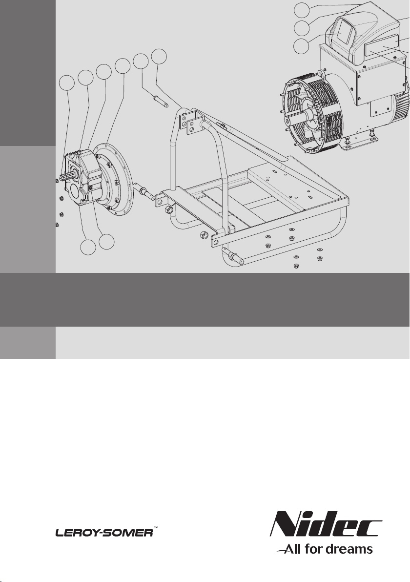
Electric Power Generation Installation and maintenance
GEARLEC - TRACTELEC
GT3 / TF3 / TM3
3472 en -
This manual concerns the alternator which you have just purchased.
We wish to draw your attention to the contents of this maintenance manual.
SAFETY MEASURES
Before using your machine for the rst time,
it is important to read the whole of this
installation and maintenance manual.
All necessary operations and interventions
on this machine must be performed by a
qualied technician.
Our technical support service will be pleased
to provide any additional information you
may require.
The various operations described in this
manual are accompanied by
recommendations or symbols to alert the
user to potential risks of accidents. It is vital
that you understand and take notice of the
following warning symbols.
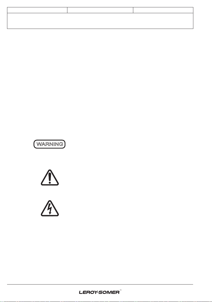
Warning symbol for an operation capable
of damaging or destroying the machine
or surrounding equipment.
Warning symbol for general danger to
personnel.
Warning symbol for electrical danger to
personnel.
SAFETY INSTRUCTIONS
We wish to draw your attention to the
following 2 safety measures which must be
complied with:
a) During operation, do not allow anyone
to stand in front of the air outlet guards,
in case anything is ejected from them.
b) Do not allow children younger than 14
to go near the air outlet guards.
A set of self-adhesive stickers depicting the
various warning symbols is included with
this maintenance manual. They should be
positioned as shown in the drawing below
once the machine has been fully installed.
WARNING
The alternators must not be put into
service until the machines in which they
are to be incorporated have been
declared compliant with EC Directives
plus any other directives that may be
applicable.
This manual is to be given to the end
user.
The range of electric alternators and
their derivatives, manufactured by us or
on our behalf, comply with the technical
requirements of the customs Union
directives.
The alternator is a sub-assembly
delivered without a system of protection
against short-circuits. The protection
must be provided by the circuit-breaker
of the generator, sized to interrupt the
fault current.
© 2022 Moteurs Leroy-Somer SAS
Share Capital: 38,679,664 €, RCS Angoulême
338 567 258.
We reserve the right to modify the characteristics
of this product at any time in order to incorporate
the latest technological developments. The
information contained in this document may
therefore be changed without notice.
This document may not be reproduced in any
form without prior authorization.
All brands and models have been registered and
patents applied for.