Flip
(Figure:11)
90°22°approx.68°Flip
0.00°
68°
68°
(Figure:12)
22°
68°
68°
1. Only press [校正/ゼロ]Button (Calibration/Zero)during calibration or zero setting. Pressing at any other
time will cause inaccurate measurements.
2. When battery is replaced, power will automatically turn on. This is normal operation; to turn off press the
[ON/OFF]Button.
3. Do not drop or subject to shock as it may cause poor accuracy.
4. The bottom of the instrument contains magnets, please keep from keep away from sensitive items such
as computers, watches, compass, etc. as it may cause a malfunction.
5. Do not disassemble instrument under any circumstances.
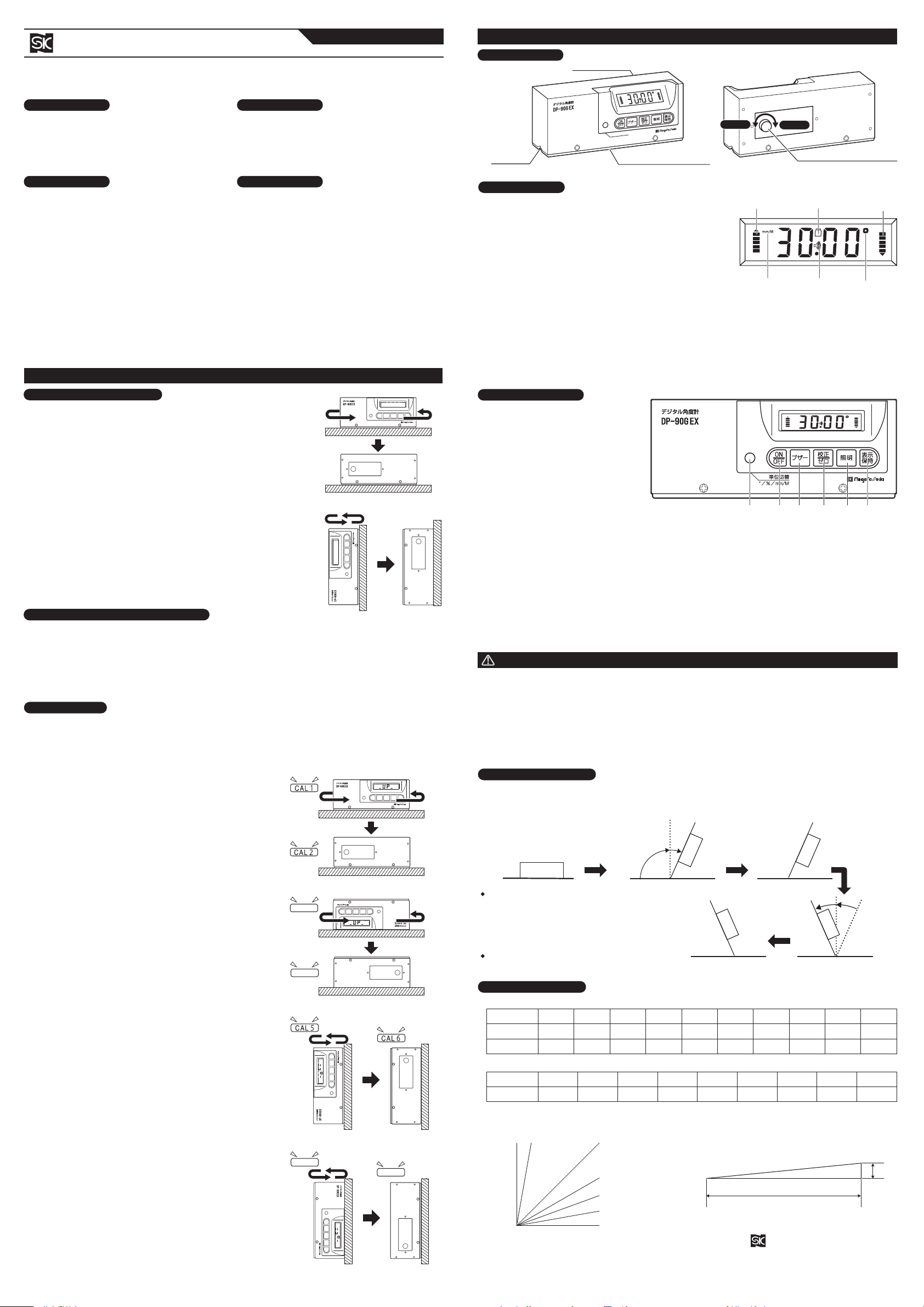
*For angle about 22°beyond 90°, Display will automatically flip to make it easier to read. (Display value of
about 68°)
Please use care when taking measurement to avoid misreading display. (Figure:11)
・
After the display flips, to return to original
direction, move back toward starting angle. For
angle about 22°beyond 90°in the other
direction, display will return to original
orientation.
(Display value around 68°)(Figure:12)
・
If position does not exceed 90°, the display will
not flip.
DIGITAL PROTRACTOR
Model No. : DP
-
90G EX
This angle gauge uses a liquid sensor to measure
the angle of inclination of the instrument.
The change in liquid level is converted to a
corresponding electrical signal and displayed on
the LCD.
●Angle can be measured as: degree (°), percent
slope (%), or gradient (mm/M).
●Display will automatically flip if gauge is upside
down for easy reading of overhead
measurements.
●Audible beep feature when measurement is: 0°,
90°, 0%, or 0 mm/M.
●Back-light feature for reading in low light areas.
Press the [照明]Button (Light)and Back-light
will turn on for approx. 1 min.
●Hold Button to allow reading when display is
inaccessible. Press [表示保持]Button (Hold)
and display reading will hold.
●V-Groove base for measuring cylindrical
surfaces. Also, Base has four magnets for
vertical or overhead measurements on steel.
Thank you for purchasing the Digital Protractor.
Please read this manual thoroughly before use for proper operation.
a. Gradient
b. Angle
Gradient
Percent
Degrees
1/200
0.5%0.3°1/150
0.7%0.4°1/115
0.9%0.5°1/100
1.0%0.6°1/80
1.3%0.7°1/50
2.0%1.1°1/40
2.5%1.4°1/30
3.3%1.9°1/20
5.0%2.9°1/10
10.0%5.7°Degrees
Percent
0.0°0.0%10.0°17.6%20.0°36.4%30.0°57.7%45.0°100%60.0°57.7%70.0°36.4%80.0°17.6%90.0°0.0%1. Make sure Base Reference Surface is clean and free of adhered
contamination or dents.
2. Press the [ON/OFF]Button to turn on, and check icon to confirm
proper units (°, %, mm/M).
〔Horizontal Accuracy Check〕(Figure:1)
3. Place gauge on a horizontal surface and turn on the power. After
display has stabilized, rotate 180°at the same position. When display
is stabilized, the reading should be same as before to confirm
accuracy.
(If readings are withing normal range of instrument error of ±0. 3°)
〔Vertical Accuracy Check〕(Figure:2)
4. Place gauge on a vertical surface with display side up, and turn on
the power. After display has stabilized, rotate gauge 180°in
horizontal direction at the same position, keeping the display on the
upper portion. When display is stabilized, the reading should be
same as before to confirm accuracy.
(If readings are withing normal range of instrument error of ±0. 3°)
*If accuracy checks, gauge is ready to take measurements.
*Calibration is required if accuracy check error is greater than ±0.4°, or under certain conditions:
●If instrument is subject shock or vibration, or large changes in temperature.
●If battery is removed, as when gauge is not used for a long time.
*Full calibration procedure of steps 1 to 17 below must be performed. Follow the figures, and us the display
“UP”text as a guide.
*Zero Point can be set at any angle of inclination.
1. At desired angle, wait for display to stabilize and press the [表示保持]
Button (Display Hold).
2.
When the display blinks, press the [校正/ゼロ]Button (Calibration/Zero).
This angle is now set as zero.
3. Press [表示保持]Button (Display Hold)again to cancel this setting. (10%=0.1)(0%)90°80°(17.6%)45°(100%)30°(57.7%)20°(36.4%)10°(17.6%)0°(0%)1/10
10
1
⑤Display Switching Button
Changes display angle - degrees (°),
percent slope (%), or gradient
(mm/M).
⑥ON/OFF Button (Power Button)
Press to turn on power, press again
to turn off.
Power will turn off automatically if
gauge is idle for about 6 min.
⑦Buzzer Button
Press once and buzzer will beep at
0°, 90°, 0%, 0mm/M. Press again to disable buzzer.
⑧Calibration / Zero Button
For use when calibrating horizontal and vertical setting, and for setting an angle as Zero-Point. (Please
refer to: “Setting Zero,”and “Calibration”sections).
⑨Light Button
Press once to turn on back-light, press again to turn off.
Light will turn off automatically in about 1 min.
⑩Display Hold Button
Press once to hold value on display. Press again to release value and resume measurements.
●Model : DP
-
90G EX
●Measuring Range : ±90.0°●Resolution : Angle Display = 0.05° Ercent Display = 0.1%
Gradient Display = 1mm/M
●Accuracy : 0.0°〜90.0°=±0.3°●Display Stabilization Time : approx. 10 sec.
●Operating Temperature : 0〜50°C
●Batteries : 9V Battery
●Dimension :
L173×W47×H68mm
(excluding protrusions)
●Weight : 550g
●Accessories : Soft case, Manual, 9V Battery (for test)
*Specifications subject to change
without notice.
●
Piping and equipment construction and installation.
●Roofing and exterior construction.
●Tile cutting and setting.
●Steel and civil engineering measurement and
construction.
Digital Display
V Groove Battery Cover Screw
〔Rear〕〔Front〕
Rotate to remove cover when
replacing Battery.
*When displaying percent slope, gauge will display angle
referenced to horizontal from 0°to 45°(0% to 100%),
and referenced to vertical for 45.1°to 90°(100% to 0%).
Tighten
Loosen
①Arrow Display (Ex:indicates angle)
●Indicates direction to adjust tilt for level. Arrows display for
angles between 0.05°〜44.9°to help in adjusting for
horizontal. (In Figure, arrows are shown for example with right
side of gauge elevated.)
●Arrows reverse at 45.1°for use as reference in vertical
measurements. (Gauge can be used in horizontal or vertical
direction.)
●Arrows shrink and go out at 0.00°, 90.00°and display as
straight bar at 45.0°②Battery Indicator
Automatically displays when battery is low.
③Buzzer Icon
Press [ブザー]Button (Buzzer)to turn on icon and buzzer will beep at 0°, 90°, 0% and 0mm/M. Press
again to disable buzzer.
④°,%, mm/M Icon
Indicates display angle is in degrees (°), percent slope (%), or gradient (mm/M).
〔Vertical Calibration〕10. Hold the Base of the Gauge on a flat surface which is roughly
vertical with the Display side up.
11. After about 15 seconds, gauge will <beep>, and display will
flash to “CAL5”. (Figure:7)
Display will then change to “UP”←→”
-
6
-
”text.
12. Rotate instrument 180°horizontally, and hold to same location
on surface.
13. Gauge will <beep>, and display will flash to “CAL6”.(Figure:8)
Display will then change to “UP”←→”
-
7
-
”text.
14. Next step is to repeat for gauge with display in the lower
position.
15.
Gauge will <beep>, and display will flash to “CAL7”. (Figure:9)
Display will then change to “UP”←→”
-
8
-
”text.
16. Rotate instrument 180°horizontally, and hold to same location
on surface.
17.
Gauge will <beep>, and display will flash to “CAL8”. (Figure:10)
*Calibration is now complete.
〔Horizontal Calibration〕1. Place the Base of the Gauge on a clean, flat surface which is
roughly horizontal and press the [ON/OFF]Button to turn on.
2. After about 15 seconds, press the [校正/ゼロ]Button
(Calibration/Zero)and hold for two seconds.
“CAL”will flash on display, and then display will change to
“UP”←→”
-
1
-
”text.
3. After about 15 seconds, gauge will <beep>, and display will
flash “CAL1”. (Figure:3)
Display will then change to “UP”←→”
-
2
-
”text.
4. Rotate instrument 180°horizontally, in same location on
surface.
5. Gauge will <beep>, and display will flash “CAL2 ”. (Figure:4)
Display will then change to “UP”←→”
-
3
-
”text.
6. Next step is to repeat for top surface of gauge.
7. Gauge will <beep>, and display will flash “CAL3 ”. (Figure:5)
Display will then change to “UP”←→”
-
4
-
”text.
8.
Rotate instrument 180°horizontally, in same location on surface.
9. Gauge will <beep>, and display will flash “CAL4 ”. (Figure:6)
Display will then change to “UP”←→”
-
5
-
”text.
*Horizontal calibration is now complete, Continue on to perform
vertical calibration.
INSTRUCTION MANUAL
単位切替°/%/mm/M
DISPLAY ORIENTATION
OPERATION
CONVERSION TABLE
CAUTION
APPLICATIONSDESCRIPTION
FEATURES
MAIN BODY
SPECIFICATIONS
PART IDENTIFICATION and FUNCTION
⑨⑩⑧⑦⑥⑤
CALIBRATION
(Figure:2)
CA L 7C A L8
(Figure:3)(Figure:4)(Figure:5)(Figure:6)(Figure:8)(Figure:7)(Figure:10)(Figure:9)
(Figure:1)
CA L 3CA L 4
Base Reference Surface
(With 4 Magnets)
〔Angle Examples〕
〔Angle Diagram〕〔Gradient Diagram〕
①①④④③②
DIGITAL DISPLAY
beep
beep
beep
beep
beep
beep
beep
beep
OPERATION BUTTON
ACCURACY CONFIRMATION
SETTING ZERO AT ARBITRARY ANGLE
Niigata seiki Co., Ltd.
5-3-14, Tsukanome, Sanjo, Niigata, Japan, 955-0055
Tel. : +81-256-33-5522 Fax. : +81-256-33-5518
MAIL intl.sales@niigataseiki.co.jp
URL http://www.niigataseiki.co.jp


