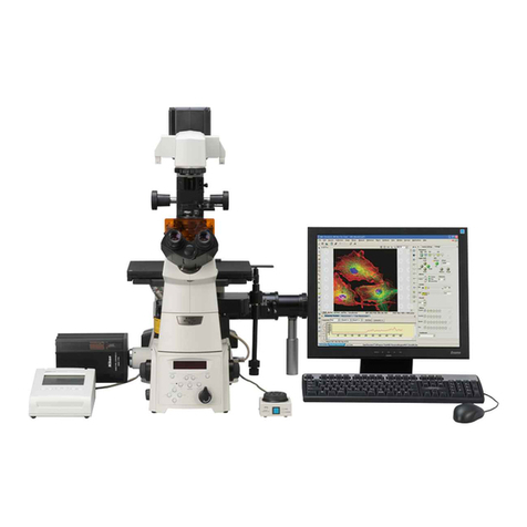
Nikon P-THSS User manual

P-THSS Teaching Head
P-THS Teaching Head Stand
P-THSS ティーチングヘッド
P-THS ティーチングヘッド用スタンド
Instructions
使用説明書


E-1
Thank you for purchasing the Nikon products.
This instruction manual is written for the users of the Nikon’s
“P-THSS teaching head and P-THS teaching head stand” and
describes their basic operations.
To ensure correct usage, read this manual carefully before
operating the instrument.
•It is prohibited to reproduce or transmit this manual in part or
whole without Nikon’s expressed permission.
•The contents of this manual are subject to change without notice.
•Although every effort has been made to ensure the accuracy of
this manual, if you note any points that are unclear or incorrect,
contact your nearest Nikon representative.
•Some of the products described in this manual may not be
included in the set you have purchased.
•Be sure to read the instruction manual for any other products
used in combination with the stand (such as the stereoscopic
microscope).
•P-THS teaching head stand can only be used with the
stereoscopic microscopes SMZ1500, SMZ1000 and SMZ800.

E-2
INames of Parts
Base
P-THS teaching
head stand
P-THSS
teaching head
Eyepiece tube mount for
the secondary observer
Eyepiece tube clamp
Eyepiece tube mount
for the main observer
Eyepiece tube clamp
Pointer mount
Screw hole for
attaching the epi-arm
Base leveling screw
Vinyl sheet
Vertical movement
clamp screw
Vertical movement
handle
Pillar
Pillar fixing screws
Focusing mount
clamp screws
Focusing mount
Focus knob
Teaching head
clamp screws

E-3
II Assembly
Required tools:
•Hexagonal wrenches (large / small)(supplied with the teaching head
stand)
•Hexagonal screwdriver (supplied with the teaching head stand)
•Hexagonal screwdriver (for mounting the pointer unit: M3)
•Minus screwdriver
1Attach the pillar to the base.
Use the large hexagonal wrench to securely
tighten the three screws.
2Attach the focusing mount to the pillar.
Slide on the focusing mount along the
dovetail mount on the pillar until it stops at
the limit pin. Tighten two clamp screws with
a minus screwdriver.
3Level the base.
Use the small hexagonal wrench to turn the
base leveling screw to stabilize the base.
Large hexagonal
wrench
Limit pin
Clamp
screws
Small hexagonal
wrench
Base
Base leveling screw
The pillar should
be attached here.

E-4
4Attach the teaching head.
Slide on the teaching head along the dovetail
mount on the focusing mount until it stops at
the limit pin. Tighten two clamp screws with
a minus screwdriver.
5Attach the stereoscopic microscope.
Attach the zooming body to the circular
dovetail mount at the bottom surface of the
main observer side of the teaching head, and
while pushing the zooming body toward the
front, tighten the clamp screw with a
hexagonal screwdriver. Be sure to hold the
zooming body with your hand until it is
securely clamped on to the teaching head.
6Attach the eyepiece tubes for the main
and secondary observers.
Matching the groove on the bottom surface of
the eyepiece tube with the pin on the mount,
attach the eyepiece tube on the teaching head.
Tighten the clamp screw with the hexagonal
screwdriver.
Limit pin
Clamp screws
(x2)
Push the
zooming
body
toward the
front and
clamp.
Pin
Groove

E-5
Assembly II
7Attach the eyepieces.
Insert the eyepieces into the eyepiece sleeves until they stop at the end
surfaces of the sleeves.
Note) The 10X eyepieces come with rubber covers. When attaching 10X
eyepieces to the eyepiece sleeves, do not hold the diopter
adjustment rings but hold their rubber covers to avoid damage to
the eyepiece. Also note that because of these covers, you cannot
check with your eyes that the eyepieces are securely inserted in
place. Feel through your fingers that they are securely inserted in
place.
8Screw on an objective to the zooming body.

E-6
III Usage
1How to Focus on the Sample
Loosen the vertical movement clamp screw and turn the vertical
movement handle to move up or down the teaching head.
Adjust the height of the teaching head so that the distance between the
objective end and the upper surface of the sample becomes almost the
same with the working distance of the objective in use. Tighten the
vertical movement clamp screw to fix the teaching head at that position.
Look into the eyepieces and turn the focus knob to precisely focus on the
sample.
●See the instruction manual supplied with the stereoscopic microscope
for the working distances of the objectives.
●Adjust the diopter before observation. See the instruction manual
supplied with the microscope for the details on the diopter adjustment.
●Avoid the following operations since they will damage the instrument.
•Turning the vertical movement handle without loosening the vertical
movement clamp screw.
•Turning the left and right focus knobs in opposite directions at the
same time.
•Turning the focus knob even after it reaches its limit of rotation.
Vertical movement clamp screw
Focus knob
Vertical movement
handle
Moves up
Working distance
of the objective

E-7
III
2Y-THP TH Pointer Unit
A guiding arrow can be shown in the right-side viewfield with the Y-THP
TH pointer unit mounted at the front of the main observer. Be sure to use
Y-THAC THAC adapter for the power supply of the Y-THP TH pointer
unit.
•When observing the sample of high reflectance, you may find several
arrow shadows in the left-side viewfield when you make the arrow very
bright. Though this is not a malfunction, you may need to darken the
arrow to make the shadows disappear.
1Mounting the pointer unit
Fix the pointer unit on the main observer side
of the teaching head with four screws using a
hexagonal screwdriver. Connect the Y-THAC
THAC adapter to the side of the pointer unit.
Connect the AC adapter to the wall outlet.
Lamphouse cover
Before replacing the lamp, turn off
the lamp with the arrow brightness
control (turn counterclockwise until
it clicks), unplug the AC adapter
from the wall outlet and wait till the
lamp cools down.
Arrow rotation dial
Turn to change the
arrow direction.
Arrow brightness control
(also functions as
the ON/OFF switch)
Turn clockwise to increase the
arrow brightness.
Turn counterclockwise until it
clicks to turn OFF the power
and to make the arrow
disappear.
Arrow control stick
Move to change the arrow position.
Arrow color selection dial
Turn to switch the arrow color between
G (green) and R (orange). This dial
should always be turned to the limit.
AC adapter plug

E-8
Groove
Lamphouse
cover
Protrusion
Luminous
part
Lamp
2Mounting (replacing) the lamp
To avoid electrical shock and burns, turn off the lamp with the arrow
brightness control (turn counterclockwise until it clicks), unplug the AC
adapter from the wall outlet and wait till the lamp cools down before lamp
replacement.
1Remove the lamphouse cover. (Push in
the cover and twist 45° to remove.)
2Insert the lamp into the socket with its
luminous part heading inside.
3Reattach the lamphouse cover.
(Matching the grooves with the
protrusions, push in and twist clockwise
till the limit.)
3Specifications
●Y-THP TH pointer unit
Type name: THP
Input voltage: DC 9V, 0.5A max.
Lamp for arrow illumination: 6V-0.2A tungsten lamp (average lifetime:
1000 hrs.)
Arrow color: Green or orange (can be selected)
Arrow illumination voltage: 0 to 6V (can be controlled by brightness
control which also functions as ON/OFF
switch)
Conforming standards: EU Low Voltage Directive satisfied.
EU EMC Directive satisfied.
●Y-THAC THAC adapter
Type name: SA-091A0F-10
Input voltage: AC 100-250 ~, 0.3A max.
Output voltage: DC 9V, 1A max.
Conforming standards: UL listed product
CSA satisfied.
EU Low Voltage Directive satisfied.
EU EMC Directive satisfied.

E-9
III
Usage
C-DSLS halogen
illuminator
Epi-arm
P-ICI2 coaxial
episcopic illuminator
3Epi-arm
Two epi-arms can be screwed onto the holes
at the bottom of the focusing mount. You can
attach the halogen illuminators to the epi-
arms. See the instruction manual supplied
with the stereoscopic microscope for the use
of halogen illuminators.
4P-ICI2 coaxial episcopic illuminator
The P-ICI2 coaxial episcopic illuminator can
be attached between the teaching head and the
zooming body. See the instruction manual
supplied with the stereoscopic microscope for
the use of P-ICI2 coaxial episcopic
illuminator.

E-10
III
Usage
Diascopic stand
5Stereoscopic microscope stand series
C-DSD115 diascopic stand 115
C-DSD230 diascopic stand 230
C-DSS115 diascopic stand 115
C-DSS230 diascopic stand 230
C-BD115 diascopic bright/dark field stand 115
C-BD230 diascopic bright/dark field stand 230
Place the diascopic stand on the base
matching their rubber feet with the dents
(φ13, depth 0.7mm) on the base. See the
instruction manual supplied with the stand for
their usage.
6Vinyl sheet
Lay the vinyl sheet on the base as necessary (such as when you do not
want your sample to get scratches, etc.).

E-11
IV Specifications
P-THSS teaching head
System magnification: 1X
P-THS teaching head stand
Stage size: 365 mm ×500 mm ×35 mm
(not including the vinyl sheet)
Vertical stroke: 200 mm
Observable height of the sample
With P-ICI2
With P-ICI2 With C-BD coaxial episcopic
Stereoscopic Objective Basic coaxial diascopic illuminator and
microscope configuration
*1
episcopic bright/dark C-BD diascopic
illuminator field stand bright/dark
field stand
SMZ1500 HR Plan Apo 0.5X 0~ 53.5 0~ 9.5 Cannot be used. Cannot be used.
HR Plan Apo 1X 0~124.2 0~ 80.2 0~39.1 Cannot be used.
HR Plan Apo 1.6X 0~132.9 Cannot be used. 0~47.8 Cannot be used.
SMZ1000 Achro 0.5X 0~ 56.5 0~ 12.5 Cannot be used. Cannot be used.
Plan 1X 0~129.5 0~ 85.5 0~44.4 Cannot be used.
Plan 1X ERGO 0~146.5 0~102.5 0~61.4 0~17.4
Plan Apo 0.5X 0~ 57.9 0~ 13.9 Cannot be used. Cannot be used.
Plan Apo 1X 0~135 0~ 91 0~49.9 0~ 5.9
ED Plan 1.5X 0~143.5 0~ 99.5 0~58.4 0~14.4
ED Plan 2X 0~141 Cannot be used. 0~55.9 Cannot be used.
SMZ800 Achro 0.5X 0~ 69.5 0~ 25.5 Cannot be used. Cannot be used.
Plan 1X 0~142.5 0~ 98.5 0~57.4 0~13.4
Plan 1X ERGO 0~159.5 0~115.5 0~74.4 0~30.4
Plan Apo 0.5X 0~ 70.9 0~ 26.9 Cannot be used. Cannot be used.
Plan Apo 1X 0~148 0~104 0~62.9 0~18.9
ED Plan 1.5X 0~156.5 0~112.5 0~71.4 0~27.4
ED Plan 2X 0~154 Cannot be used. 0~68.9 Cannot be used.
*1 “Basic Configuration” is the word used to describe the status of mounting
stereoscopic microscope to the THSS teaching head fixed on the THS
teaching head stand.
●The ED Plan 2X and HR Plan Apo 1.6X objectives cannot be used together
with the P-ICI2 coaxial episcopic illuminator.
●The above figures are those when the vinyl sheet is not used. Using the
vinyl sheet decreases the above observable heights by 1.5 mm.
Unit: mm

J-1
この度はニコン製品をお買い上げ頂き、まことにありがとうござ
います。
この使用説明書は、実体顕微鏡用ティーチング装置の使用者のた
めに書かれたものです。
ご使用前に良くお読みになり、正しくお使いくださいますようお
願い致します。
•本書の内容の一部、または全部を無断で転記することは禁止されて
います。
•本書の内容については、将来予告なしに変更することがあります。
•本書の内容については万全を期しておりますが、万一不可解な点や、
誤り、お気付きの点がございましたら、ご購入先にご連絡ください
ますようお願い致します。
•本書に掲載されている製品の中には、ご購入頂いたセットに含まれ
ないものがある場合もあります。
•実体顕微鏡や同軸落射照明装置など、同時にお使いになる製品の使
用説明書も併せてお読みになり、そこに書かれた指示は必ずお守り
ください。
•P-THS ティーチングヘッド用スタンドは、SMZ1500、
SMZ1000、および SMZ800 専用です。

J-2
I各部の名称
ベース
P-THSティーチング
ヘッド用スタンド
P-THSS
ティーチングヘッド
従観察側鏡筒受け
鏡筒クランプねじ
主観察側鏡筒受け
鏡筒クランプねじ
ポインタユニット
取付け部
エピアーム取付け穴
ベース高さ調節ねじ
塩ビシート
上下動クランプねじ
上下動ノブ
上下動部
上下動部固定ねじ
焦準装置クランプねじ
焦準装置
焦準ノブ
ティーチングヘッド
クランプねじ

J-3
II 取付け方
必要な工具: 六角レンチ(大・小)(スタンドに付属)
六角ドライバ(スタンドに付属)
六角ドライバ(ポインタユニット取付け用:M3)
マイナスドライバ
1上下動部をベースに取り付けます。
付属のねじ 3 本を使って、六角レンチ(大)でしっ
かりと固定してください。
2焦準装置を上下動部に取り付けます。
上下動部のアリに、焦準装置を制限ピンに当たるま
で差し込みます。2 本のクランプねじをマイナスド
ライバでしっかりと締め、固定します。
3ベースががたつかないよう調整します。
ベース高さ調整ねじを六角レンチ(小)で回して、が
たつかないよう調整します。
六角レンチ(大)
制限ピン
クランプ
ねじ
六角レンチ(小)
ベース
上下動部
取付け位置
ベース高さ調整ねじ

J-4
4ティーチングヘッドを取り付けます。
焦準装置のアリに、ティーチングヘッドを制限ピン
に当たるまで差し込みます。2 本のクランプねじを
マイナスドライバでしっかりと締め、固定します。
5実体顕微鏡を取り付けます。
主観察側の底面にある丸アリに、顕微鏡のズーム本
体をはめ込み、手前側に押しつけた状態で、六角ドラ
イバでクランプねじを締めます。ズーム本体の固定
が終わるまで、しっかりと顕微鏡を支えておいてく
ださい。
6主観察側、従観察側の鏡筒を取り付けます。
鏡筒底部にある溝と、鏡筒受けのピンを合わせて鏡
筒を取り付け、六角ドライバでクランプねじを締め
て固定します。
制限ピン
クランプねじ
(2ヶ所)
顕微鏡を
手前側に
押しつけ
ながら
クランプ
する。
ピン
溝

J-5
取付け方 II
7接眼レンズを取り付けます。
鏡筒のスリーブ端面に当たるまでしっかりと差し込みます。
注)10×接眼レンズにはゴムカバーが付いていて、端面が見えませんので感触で確
かめてください。視度調節リングを持って押し込むと故障の原因となりますの
で、ゴムカバーの部分を持って差し込んでください。
8顕微鏡のズーム本体に対物レンズをねじ込みます。

J-6
III 使用方法
1ピントの合わせ方
上下動クランプねじを緩め、上下動ノブを回すと装置全体が上下します。
試料と対物レンズ先端が、使用対物レンズの作動距離に等しくなるよう調節し、上下
動クランプねじを締めて固定します。
接眼レンズをのぞきながら、焦準ノブを回して、試料に正確にピントを合わせます。
● 対物レンズの作動距離については、実体顕微鏡に付属の使用説明書をご覧くださ
い。
● 視度調節を行ってからお使いください。視度調節については、実体顕微鏡に付属の
使用説明書をご覧ください。
● 故障の原因となりますので、次のような操作を行わないでください。
•上下動クランプねじ締めたまま、上下動ノブを回す。
•左右の焦準ノブをそれぞれ逆の方向に回す。
•焦準ノブを制限に当たった後も更に回転させる。
上下動クランプねじ
焦準ノブ
上下動ノブ
上がる
作動距離

J-7
2Y-THPTH ポインタユニット
主観察側の前面に Y-THPTH ポインタユニットを取り付けると、右側の視野内に矢
印を表示させることができます。Y-THPTH ポインタユニットは、必ず Y-THAC
THAC アダプタといっしょにお使いください。
•反射率の高い試料を観察する場合、矢印を明るくしすぎると、左視野に複数の矢
印が見えることがありますが、故障ではありません。矢印の明るさを調節して観
察してください。
1取付け方
ティーチングヘッド前面にポインタユニットを取り
付け、M3の六角ドライバを使って、4本のねじを締
め、固定します。ポインタユニットの側面にY-THAC
THACアダプタを接続します。最後に、ACアダプタ
のプラグをコンセントに接続します。
III
ランプカバー
ランプ交換は、ランプが冷えてから
行ってください。ランプ交換時は、矢
印調光ボリュームを反時計方向にカ
チッと音がするまで回して矢印を消
灯し、ACアダプタをコンセントから
抜いてください。
矢印回転ダイヤル
回すと、矢印の向きが
変わります。
矢印調光ボリューム
(ON/OFFスイッチ兼用)
時計方向に回すと矢印が明るく
なります。反時計方向にカチッ
と音がするまで回すと電源が
OFFになり、矢印が消灯します
。
矢印移動つまみ
矢印の場所が移動します。矢
印が視野の外にある場合は、矢
印移動つまみを操作して、矢印
を視野内に戻してください。
矢印色切替えダイヤル
Gの方向に回すと緑、Rの方向に回
すとオレンジ色の矢印になります。(ダ
イヤルは制限まで回してください。)
ACアダプタのプラグ
This manual suits for next models
1
Table of contents
Other Nikon Laboratory Equipment manuals
Popular Laboratory Equipment manuals by other brands

Cole Parmer
Cole Parmer Stuart SC6PLUS quick start guide

Atlas Scientific
Atlas Scientific EZO-PMP manual

Specac
Specac GS10890 user manual

Tuttnauer
Tuttnauer 2840 EL-D Operation & maintenance manual

NuAire
NuAire NU-1582 Operation and installation instructions

Steinberg Systems
Steinberg Systems SBS-TWB-2000 user manual