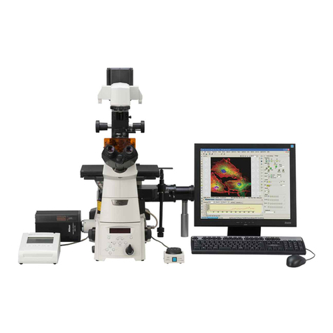
Nikon TIRF2 User manual

TIRF2 SYSTEM FOR TE2000
INSTRUCTIONS
M339E 04.12.NF.2


1
Introduction
Thank you for purchasing Nikon products.
This manual is written for the users of Nikon’s TIRF2 system for TE2000.
This product uses a laser as a light source.
Lasers are potentially hazardous and may cause injuries if directed at the eye or skin as a result of improper use.
Before using the system, carefully read the precautions concerning correct use provided at the beginning of this
manual.
• No part of this manual may be reproduced or transmitted in any form without the prior consent of Nikon.
• The contents of this manual are subject to change without notice.
• Every effort has been made to ensure the accuracy of this manual. If you find that any portion of this
manual is unclear or incorrect, please contact your nearest Nikon representative.
• This manual may describe products not included in the set purchased.
• Also be sure to read the manuals supplied with the products (microscope main unit, lasers, and super
high pressure mercury lamp power supply unit, etc).

2
Safety Precautions
WARNING and CAUTION Symbols
Although Nikon products are designed to provide the utmost safety during use, incorrect usage or failure to follow the
safety instructions provided may cause personal injury or property damage. Damage or injury that may occur due to
mishandling is unwarranted. To ensure correct use, read the instruction manual carefully and thoroughly before using
the instrument. Do not discard the manual; keep it handy for easy reference.
Safety instructions within this manual are accompanied by the following symbols to highlight their importance. For
your safety, always follow the instructions accompanying these symbols.
Symbol Meaning
Disregarding instructions accompanying this symbol may lead to serious injury or death.
Disregarding instructions accompanying this symbol may lead to injury or property
damage.
The symbol appearing on the product indicates the need for caution at all times during use.
Always refer to the instruction manual and read the relevant instructions before manipulating any part to which the symbol
has been affixed.
Symbol Meaning
Laser Warning Label - Symbol for Danger
This symbol is displayed on the stage to warn that the equipment emits lasers.
Your eyes or skin may be exposed to the laser beam emitted from the objective, resulting in injury.
Caution for heat.
This marking at the top part of the Dia-illuminator and the 12V100W lamphouse calls your attention on the
following;
•Lamphouse becomes very hot during and immediately after the illumination.
•Risk of burns. Do not touch the lamphouse during and immediately after the illumination.
•Make sure that the lamphouse is sufficiently cool before the lamp replacement.
Biohazard
This symbol on the stage calls your attention to the following:
•Spillage of a sample from a vessel onto the microscope presents a biohazard risk.
•To avoid biohazard contamination, do not touch the contaminated portion with your bare hands.
•Decontaminate the contaminated portion according to the standard procedure of your laboratory.
Risk of electric shock.
This symbol labeled on the rear of the lamphouse calls your attention on the following.
•To avoid electric shock, do not touch the lamphouse or the lamp socket while the IGNITION switch on
the power supply is depressed. (While the IGNITION switch is depressed, the high voltage of
approximately 2kV at maximum is supplied to the lamp.)
•In case of emergency, pull off the power cord from the power supply. (The power supply will then be
isolated from the main power source.)
•To avoid electric shock, turn OFF the power of the power supply (press down to the side), pull off the
power cord from the wall outlet and confirm that the POWER monitor lamp is extinguished, before
exchanging the lamp or connecting/disconnecting the cables.
WARNING
CAUTION
Meaning of symbols used on the equipment

Safety Precautions
3
Use of controls or adjustments or performance of procedures other than those specified in this manual
may result in hazardous radiation exposure.
1. Laser safety
This product is designed and built in compliance with the Performance Standards for Light-Emitting
Products established by the U.S. FDA and the IEC Laser Product Safety Standard (IEC 60825-1), except
for deviations pursuant to Laser Notice No.50. Users are requested to take all appropriate safety
measures specified by the preceding standards, in accordance with local laws and regulations.
FDA Class II Laser Product
IEC Class 2 Laser Product
2. Intended product use
This product may be used only for microscopic observations. It must be mounted to the specified Nikon
microscope model TE2000-E/U/S. It may not be used for any other purpose.
3. Setting up this product
Setup of this product must be handled by trained service personnel.
This task should not be performed by anyone other than the trained service personnel. If so, may
result in improper setup, impairing system performance and exposing the eyes or skin to the laser
beam, resulting in injury.
4. Prohibition of dismount
This product uses laser light. Use only in the configuration set up by the Nikon representative. To
ensure safety, never attempt to remove any part of the system. Before beginning operations, confirm
that all of the parts listed below are in place. Removal of any part during use may result in unintended
exposure of eyes or skin to laser light. Make sure that all power to the laser and entire system is
turned off when removing an objective or filter cube.
Eyepiece tube, nosepiece, objective, TIRF2 attachment, filter cube, stage, lamphouse, cassette holder
for Epi-fl microscopy, TV camera, all port caps
5. Do not disassemble
Disassembling this product may result in electric shock or other hazards.
Never attempt to disassemble any piece of equipment included in this product.
In particular, disassembling any of the components when the laser is on may cause the laser beam to
be improperly emitted from this product. If you discover that this product is not functioning properly,
immediately stop use, switch off the power switches to all pieces of equipment, disconnect the power
cables from the outlets, and contact your nearest Nikon representative.
6. Pre-operation check items
Before using the system, always confirm the followings.
If the following conditions are not met, laser light may be irradiated from openings or reflected from
reflective objects, and unintended exposure of eyes and skin to laser light may result.
1) an objective or cap is in place on each of the nosepiece sockets;
2) a dia-illumination lamphouse is attached;
3) an episcopic illumination lamphouse is attached;
4) caps or TV cameras are in place on all ports;
5) there are no mirrors or other highly reflective pieces of metal in the area surrounding the lens
aperture.
6) the eyepiece shutter is attached;
7) the cassette holder is attached;
WARNING

Safety Precautions
4
7. Never look into the laser beam
When the laser is on, a powerful beam of light is emitted above and below the stage through the
objectives. Never look into this beam or reflected beams. To prevent reflection of the laser beam
emitted from the objectives and resulting inadvertent exposure of eyes or skin to laser light, never
place reflective objects on the stage or in the diascopic optical path.
8. Heat from the light source
The symbol of on the rear of the lamphouse call your attention on the following.
The lamp and the lamphouse become extremely hot while the lamp is on and immediately after it is
turned off. Follow the guidelines below to avoid burn injury and to prevent fire.
• Never touch the lamp, lamphouse, or surrounding area while the lamp is lit or within 30 minutes
after switching off the power.
• Allow the lamp and surrounding area to cool sufficiently before replacing the lamp bulb.
• Do not allow walls, curtains or paper documents to contact the area surrounding the
lamphouse.
• Do not allow cloth, paper, or highly flammable volatile materials, such as gasoline, benzene,
thinner or alcohol, to come near the lamp or the surrounding area while the lamp is lit or within
30 minutes after switching off the power.
9. Mercury lamps
The mercury lamp used with this system requires special handling. In order to use this system safely
and correctly, carefully read the warnings below and beware of the dangers. Also carefully read the
manual for the super high-pressure mercury lamp power supply (or high-intensity light source) and the
manual (if provided) by the manufacturer of the lamp and follow their instructions.
The Hazards of Mercury Lamps
1 Mercury lamps radiate ultraviolet light that is harmful to the eyes and skin when they are turned
on. Direct viewing of light from these lamps may result in blindness.
2 Gas is sealed under very high pressure inside the lamps. The pressure increases when the lamp is
on.
If the lamp is scratched, dirty, subjected to high external pressure or physical impact, or used
beyond its operational life, the sealed gas may escape or the lamp may burst. This can result in
someone inhaling the gas, injuring themselves on the glass, or other accidents.
3 When the lamp is on, the lamp and its surroundings become extremely hot. Touching the lamp with
bare hands could result in burns. Flammable materials placed near the lamp could ignite.
4 Using other than the specified type of lamp could result in an accident, such as a burst.
Because safety is a top priority in the design of Nikon products, the hazards described above should not
pose any danger as long as you heed all of the warnings and cautions in the manuals and use the
system only for its intended purpose. However, the hazards described above could lead to an accident
if you fail to heed all of the warnings and cautions in the manuals, if you strike the system, or if you
attempt to disassemble the system. Therefore, always be sure to heed all of the warnings and cautions.
10. Use the ultraviolet light shield
Do not directly see the light irradiated from the objective. Harmful excitation light will be given out
from the objective depending on the excitation method used. When you see the part around the
objective, be sure to see through the ultraviolet light shield.
WARNING

Safety Precautions
5
1. Power supply ratings and power supply cords
Before connecting equipment power cords to their outlets, check your power-line ratings to make sure
that the input voltage and current-carrying capacity requirements of equipment are met. Use of a
non-conforming power line may result in equipment malfunction, failure, or fire. Always use power
cords that satisfy local safety regulations. Always use three-pole grounded outlets.
For power cord specifications, see “VIII Performance and Specifications.”
2. AC adapter
The shutter control unit is powered by the AC adapter. Be sure to use specific adapter model meeting
the requirements. Use of any other type of adapter can result in malfunction, excessive heating, and/or
fire. For AC adapter specifications, see “VIII Performance and Specifications.”
• To prevent malfunction and/or fire, be sure to use the AC adapter in a well-ventilated location.
To ensure that it radiates heat properly and does not overheat, never cover or place any object
on the adapter.
• To prevent malfunction, always turn off the power switch (switch to “O”) of the shutter control
unit before attaching the AC adapter.
3. Cable connections
Always switch off the power switches to all equipment before connecting or disconnecting cables.
To prevent broken wires, do not pull cables by the sheath; instead, firmly grasp the plug when
connecting or disconnecting a cable.
4. Response if the system operates abnormally
If you discover that the system is not functioning properly, switch off all power switches, and
disconnect power cords from the outlets.
5. Prevent contact with moisture
Water splashed onto any component of this product may cause short circuits, resulting in malfunction.
If a piece of equipment is subject to contact with water, immediately switch off the power switch to
that piece of equipment and wipe off the water with a dry cloth. If water enters a component,
immediately suspend use of this product, disconnect the power cord from the outlet, and contact your
nearest Nikon representative.
6. Do not place any objects on system equipment
To prevent deformation, failure, or malfunction, and to avoid injury, never place any objects (heavy
ones in particular) on any component of the system.
CAUTION

Safety Precautions
6
7. Handling
1. Handle with care
This product is a precision optical instrument. Make sure that the product is not subject to shock;
handle equipment gently. Also be sure to handle cables with care. Optical-fiber cables, in
particular, must not be bent or pulled with excessive force, to prevent failure, malfunction, or
broken wires.
2. Installation conditions
To ensure safe and reliable operations, observe the following conditions when installing this
product:
• To prevent equipment from falling and to avoid eventual failure, install each component of
this product on a level surface.
• To prevent performance degradation caused by dust or other foreign particles, use this
product in a clean environment.
• Use this product at ambient temperatures of between +5 and +35°C and in conditions of
humidity of 60% or less (no condensation). To prevent condensation and failure, never
attempt to use this product under conditions of high temperature and humidity.
• Make sure that this product is not subject to strong vibrations, which may degrade image
quality. Consult with your Nikon representative about preventive measures you may take
when this product is installed.
• To prevent degradation, malfunction, or failure of your laser units and PC, always use power
supply that is free from electric noice or sudden voltage fluctuations.
• To prevent failure, do not block or place any obstacles near the cooling fans of the controller
or laser units. If a particular piece of equipment is installed close to a wall, be sure to provide
at least 15 cm of space between the wall and the equipment.
3. Cleaning
Use a dry and soft cloth to clean painted, plastic, and printed parts. If necessary, wipe these parts
with a cloth moistened with diluted neutral detergent, then wipe off the moisture with a soft and
dry cloth. To prevent discoloration or deformation of painted or plastic parts or removal of the
printed letters/figures, do not use organic solvents such as paint thinner or alcohol.
4. Other precautions
Be sure to follow the instructions specified in this manual. Failure to do so may result in impaired
performance, malfunction, failure, or unexpected hazards.
CAUTION

Contents
7
Contents
I System configurations and names ................................................................... 9
1 Full view ..................................................................................................................9
2 Laser path ............................................................................................................. 11
2.1 Laser unit...................................................................................................... 11
2.2 Microscope part.............................................................................................. 12
3 Safety labels .......................................................................................................... 13
3.1 TE2000 ......................................................................................................... 14
3.2 Two-laser unit C-LU2 ................................................................................... 15
3.3 Three-laser unit C-LU3................................................................................. 16
3.4 Three-laser unit C1-LU3............................................................................... 17
3.5 Shutter control unit (T-LUSU, T-LUSU2) ............................................................ 18
3.6 TIRF2 attachment........................................................................................... 19
4 Names of component parts...................................................................................... 20
4.1 Microscope part.............................................................................................. 20
4.2 Laser unit...................................................................................................... 22
II Rough Sequence of Microscopy ..................................................................... 23
III Detailed Sequence of Microscopy................................................................... 24
0 Preparation before microscopy ................................................................................. 24
0.1 Center the Epi illumination lamp....................................................................... 24
0.2 Adjust the diopter and the interpupillary distance............................................... 24
1 Safety check.......................................................................................................... 24
2 Startup tasks......................................................................................................... 25
2.1 Emitting the laser........................................................................................... 25
2.2 Turning on power to other components ............................................................. 26
3 Epi-fl microscopy (bring the specimen into focus)....................................................... 27
4 Simple surface reflection interference microscopy using Epi-fl attachment (checking the
state where the specimen contacts to the cover glass)................................................ 29
5 TIRF microscopy .................................................................................................... 30
6 Termination tasks................................................................................................... 32
IV Part Descriptions......................................................................................... 33
1 TIRF2 attachment .................................................................................................. 33
2 Specimen cover ..................................................................................................... 38
3 Eyepiece shutter .................................................................................................... 39
4 Shutter control unit (T-LUSU, T-LUSU2) .................................................................... 40
5 T-FLC-HQ cassette holder ........................................................................................ 42
6 Laser unit.............................................................................................................. 46
V Shutter Control Unit Communications Commands ............................................ 48
1 Communication-controlled operation......................................................................... 48
VI Troubleshooting Tables................................................................................. 52
VII
Care and maintenance ................................................................................. 55
1 Replacing the objective and the filter cube ................................................................ 55
2 Replacing the lamp................................................................................................. 55
3 Cleaning the filter and the lens ................................................................................ 55
4 Cleaning the product .............................................................................................. 56

Contents
8
5 Disinfecting the product .......................................................................................... 56
6 Storage................................................................................................................. 56
7 Moving and relocating the system (charged).............................................................. 56
8 Periodical inspection (charged) ................................................................................ 56
VIII
Performance and Specifications ..................................................................... 57
1 Overall configuration .............................................................................................. 57
1.1 Shutter control unit ........................................................................................ 60
1.2 AC adapter for shutter control unit ................................................................... 60
1.3 Power cord for AC adapter of shutter control unit ............................................... 60
1.4 Environment .................................................................................................. 60
1.5 Compatible standards ..................................................................................... 61

9
System configurations and names
I
1 Full view
Full View (Front diagram)
* For details, see section 1, “Overall configuration,” in chapter VIII, “Performance and specification.”
(1) Power supply for laser unit
(2) Laser unit
(3) PC
(4) Optical fiber
(5) Shutter control unit
(6) AC adapter
(7) TV camera
(8) Eyepiece shutter
(9) Cassette holder
(10) Power supply for microscope
(11) TIRF2 attachment
(12) Light source for the Epi-illumination attachment (Super high pressure
mercury lamp housing is indicated in the figure.)
(13) Power supply of the light source for the Epi-illumination attachment (Power
supply of the super high pressure mercury lamp is indicated in the figure.)
(
1
)
(
2
)
(4)
(
6
)
(7)
(
8
)
(
10
)
(
9
)
(
12
)
(
13
)
(
3
)
(5)
(
11
)

I System configurations and names
1 Full view
10
Full View (from top)
* For details, see section 1, “Overall configuration,” in chapter VIII, “Performance and specification.”
(1) Power supply for laser unit
(2) Laser unit
(3) PC
(4) Optical fiber
(5) Shutter control unit
(6) AC adapter
(7) TV camera
(8) Eyepiece shutter
(9) Cassette holder
(10) Power supply for microscope
(11) TIRF2 attachment
(12) Light source for the Epi-illumination attachment (Super high pressure
mercury lamp housing is indicated in the figure.)
(13) Power supply of the light source for the Epi-illumination attachment (Power
supply of the super high pressure mercury lamp is indicated in the figure.)
(1)
(2)
(
3
)
(5)
(8)
(6)
(10)
(9)
(12)
(13)
(
7
)
(4)
(11)

I System configurations and names
2 Laser path
11
2 Laser path
2.1 Laser unit
(1) Laser mounting position L1 (See table below.)
(2) Laser mounting position L2 (See table below.)
(3) Laser mounting position L3 (See table below.)
(4) Motorized shutter
(5) ND filter (ND4, ND8)
(6) Laser synthesis mirror
(7) Laser out (single-mode fiber)
Laser mounting position
L1 L2 L3
Two-laser unit
C-LU2 405nm to 514nm 532nm to 640nm -
Three-laser unit
C-LU3
405nm to 440nm
633nm to 640nm 488nm to 514nm 532nm to 561nm
Three-laser unit
C1-LU3 488nm to 514nm 532nm to 543nm 594nm to 633nm
(
2
)
(1)
(
3
)
(
7
)
(
2
)
(1)
(4)
(5)
(
3
)
(7)
(6)
(
1
)
(
4
)
(
5
)
(
2
)
(7)(6)
Two-laser unit
C-LU2
Three-laser unit
C-LU3
Three-laser unit
C1-LU3
(4)
(5)
(6)

I System configurations and names
2 Laser path
12
2.2 Microscope part
1. TE2000 MICROSCOPE
2. TE2000 MICROSCOPE (from top)
Laser beam
Laser beam

I System configurations and names
3 Safety labels
13
3 Safety labels
(1) IEC laser warning label -
hazard symbol
(2) IEC explanatory label
Class 2 laser product
(3) Model name and serial
number label
(4) Safety standard label
(5) IEC caution label-
Class 3B areas
(6) IEC caution label-
Class 2 areas
(7) IEC caution label-
Class 2 areas

I System configurations and names
3 Safety labels
14
3.1 TE2000
(1) IEC laser warning label -
hazard symbol
(2) IEC explanatory label
Class 2 laser product
(Labels on stage)
(
2
)
(
1
)

I System configurations and names
3 Safety labels
15
3.2 Two-laser unit C-LU2
(1) IEC laser warning label -
hazard symbol
(5) IEC caution label -
Class 3B areas
(
5
)
(
1
)

I System configurations and names
3 Safety labels
16
3.3 Three-laser unit C-LU3
(1) IEC laser warning label -
hazard symbol
(5) IEC caution label -
Class 3B areas
(
5
)
(
1
)

I System configurations and names
3 Safety labels
17
3.4 Three-laser unit C1-LU3
(1) IEC laser warning label -
hazard symbol
(5) IEC caution label -
Class 3B areas
(
5
)
(
1
)

I System configurations and names
3 Safety labels
18
3.5 Shutter control unit (T-LUSU, T-LUSU2)
(4) Safety standard label
(Back)
* This label is used on both of the T-LUSU and T-LUSU2.
(
4
)
Table of contents
Other Nikon Laboratory Equipment manuals
Popular Laboratory Equipment manuals by other brands

WHITESTAR
WHITESTAR SIGNATURE Owners and operation manual

Waters
Waters ACQUITY UPLC H-Class Series System guide

Diagon
Diagon Coag2D user manual

NoiseKen
NoiseKen SWCS-931SD instruction manual

Varex Imaging
Varex Imaging Claymount Optica 10 Series user manual

Velp Scientifica
Velp Scientifica HSC instruction manual

Caiman
Caiman NITEHOG TIR-M50 manual

Beckman Coulter
Beckman Coulter Allegra 64R Instructions for use

Kilowatt Labs
Kilowatt Labs Sirius 3550-48-B-1.7C-M-SD-A-L-19G user manual

ecodyst
ecodyst HYDROGEN operating manual

Labnet
Labnet Spectrafuge 24D instruction manual

Delsys
Delsys Trigno Avanti Research+ quick start guide