Hermle Z 167 M User manual

© Hermle Labortechnik GmbH Z167M_V1.18_eng
Operating Manual for
Microlitre Centrifuge
Z 167 M


CONTENTS
© Hermle Labortechnik GmbH Z167M_V1.18_eng I
1. PRODUCT DESCRIPTION ..................................................................................................1
1.1 Safety Instructions ............................................................................................................................................ 1
1.2 Indended Purpose ............................................................................................................................................. 1
1.3 Brief Description................................................................................................................................................ 1
1.4 Delivery Package ............................................................................................................................................... 1
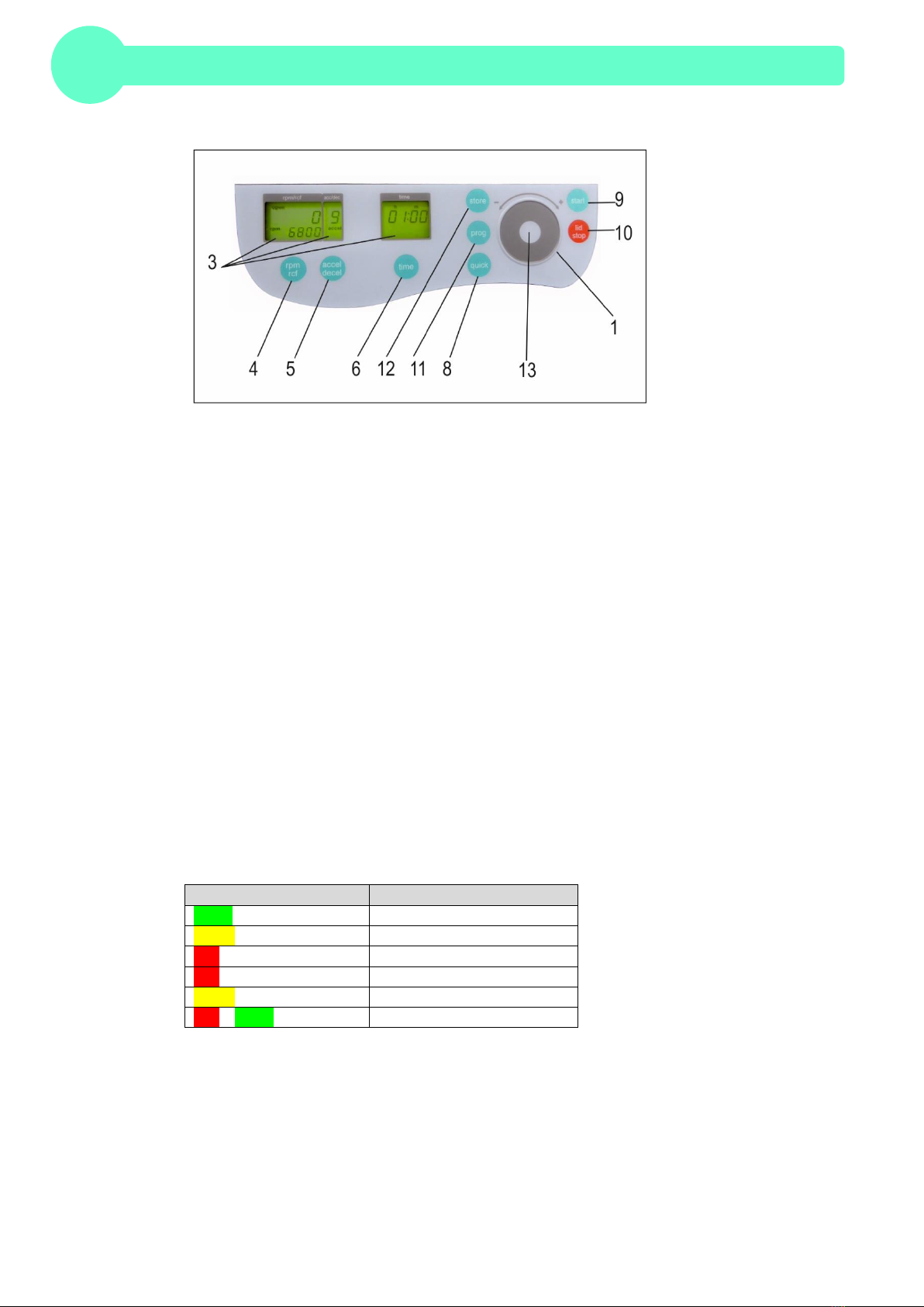
1.5 Operating and Display Elements...................................................................................................................... 2
1.5.1 LED light......................................................................................................................................................... 2
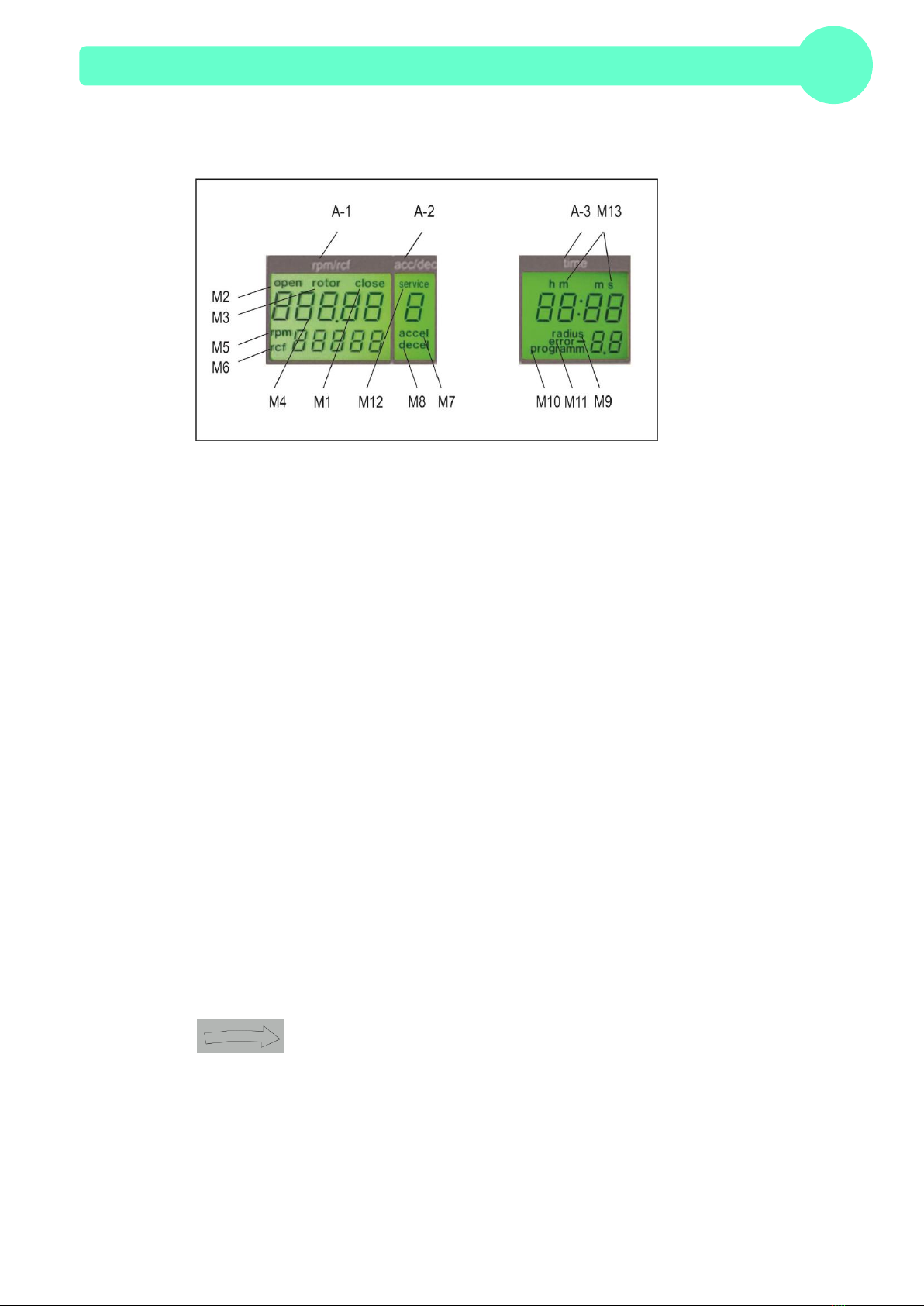
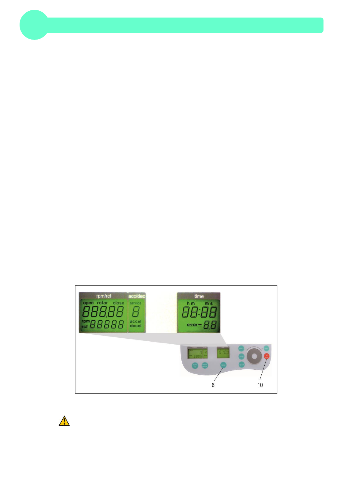
1.5.2 LCD-Display .................................................................................................................................................... 3
1.6 Signs- and Indication of the Centrifuge........................................................................................................... 3
1.6.1 General............................................................................................................................................................ 3
1.6.2 Product Nameplate (Example) ........................................................................................................................ 4
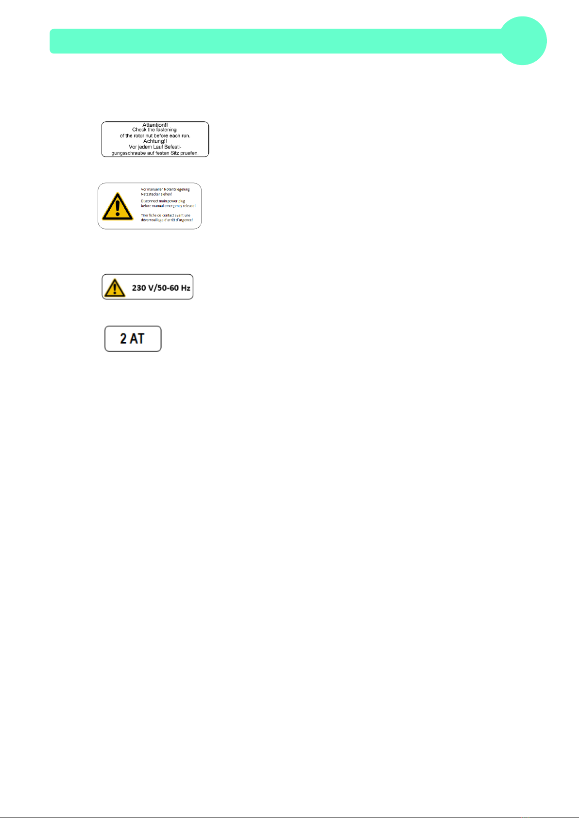
1.6.3 Warning and Information Signs ....................................................................................................................... 5
1.6.4 Danger, Precautions and Warranty ................................................................................................................. 6
1.6.5 Following Rules Must Strictly be Adhered To:................................................................................................. 6
1.6.6 Warranty.......................................................................................................................................................... 7
1.7 Installation of the Centrifuge ............................................................................................................................ 7
1.7.1 Unpacking the Centrifuge................................................................................................................................ 7
1.7.2 Space Requirements....................................................................................................................................... 7
1.7.3 Installation ....................................................................................................................................................... 7
1.8 Basic Adjustment .............................................................................................................................................. 8
1.8.1 Adjustment of the Rotor Type.......................................................................................................................... 8
1.8.2 Access to the Mode: “Standard settings“......................................................................................................... 8
1.8.3 Signal Turn On / Off ....................................................................................................................................... 9
1.8.4 Keyboard Sound Turn On / Off........................................................................................................................ 9
1.8.5 Sleep Mode On / Off...................................................................................................................................... 10
1.8.6 Retrieving Operation Data............................................................................................................................. 10
2. OPERATING......................................................................................................................11
2.1 Mounting and Loading the Rotor ................................................................................................................... 11
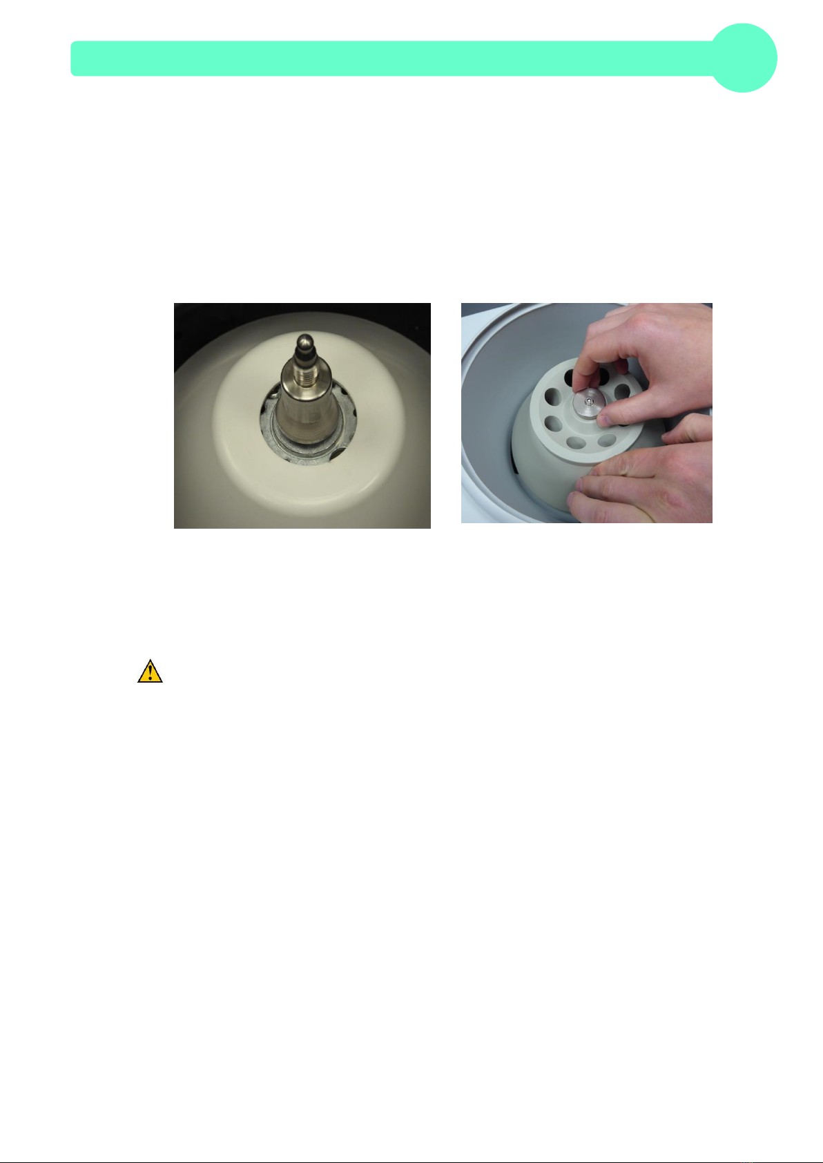
2.1.1 Installation of Rotors...................................................................................................................................... 11
2.1.2 Loading the Angle Rotor................................................................................................................................ 12
2.1.3 Loading and Overloading of Rotors............................................................................................................... 12
2.1.4 Removing the Rotor ...................................................................................................................................... 12
2.2 Power Switch, Fuse......................................................................................................................................... 13
2.3 Lid ..................................................................................................................................................................... 13
2.3.1 Lid Release ................................................................................................................................................... 13
2.3.2 Lid Lock......................................................................................................................................................... 14
2.4 Pre-Selection.................................................................................................................................................... 14
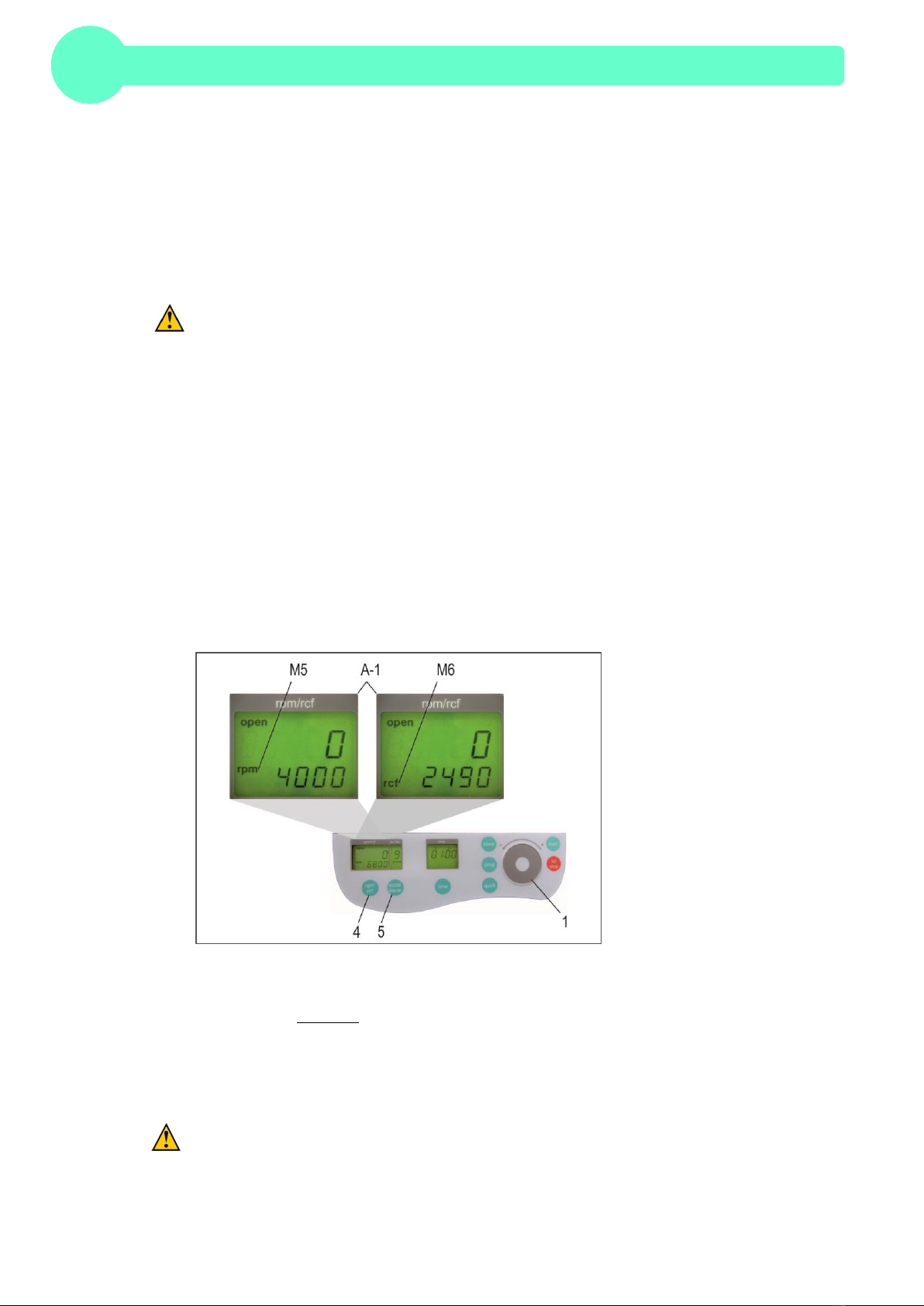
2.4.1 Pre-Selection of Speed and RCF-Value........................................................................................................ 14
2.4.2 Pre-Selection of Running Time...................................................................................................................... 15
2.4.3 Pre-Selection of Brake Intensity and Acceleration......................................................................................... 15
2.5 Radius Correction............................................................................................................................................ 16
2.6 Program............................................................................................................................................................ 17
2.6.1 Storage of Programs ..................................................................................................................................... 17

CONTENTS
II Z167M_V1.18_eng © Hermle Labortechnik GmbH
2.6.2 Recall of Stored Programs ............................................................................................................................ 18
2.6.3 Leaving Program Mode................................................................................................................................. 18
2.7 Starting and Stopping the Centrifuge............................................................................................................ 18
2.7.1 Starting the Centrifuge................................................................................................................................... 18
2.7.2 The “STOP” KEY........................................................................................................................................... 19
2.8 Imbalance Detection........................................................................................................................................ 19
3. MAINTENANCE.................................................................................................................21
3.1 Maintenance and Cleaning.............................................................................................................................. 21
3.1.1 General.......................................................................................................................................................... 21
3.1.2 Cleaning and Disinfection of the Unit ............................................................................................................ 22
3.1.3 Cleaning and Disinfection of the Rotor.......................................................................................................... 22
3.1.4 Disinfection of PP-Rotors .............................................................................................................................. 22
3.1.5 Glass Breakage............................................................................................................................................. 23
3.2 Lifetime of Rotors and Accessories............................................................................................................... 23
4. TROUBLE SHOOTING ......................................................................................................24
4.1 Error Message: Problem / Solution................................................................................................................ 24
4.2 Survey of Possible Error Messages and Solutions ...................................................................................... 24
4.2.1 Lid Release during Power Failure (Emergency Lid Release)........................................................................ 24
4.2.2 Description of the Error Message System..................................................................................................... 25
5. RECEIPT OF CENTRIFUGES TO REPAIR .......................................................................26
6. TRANSPORT, STORAGE AND DISPOSAL......................................................................27
6.1 Transport.......................................................................................................................................................... 27
6.2 Storage ............................................................................................................................................................. 27
6.3 Disposal............................................................................................................................................................ 27
7. APPENDIX........................................................................................................................... I
EG –Conformity Declaration ................................................................................................................................... II
Table 1: Technical Data ......................................................................................................................................... III
Table 2: Error Messages.........................................................................................................................................IV
Table 3: Radius Correction .....................................................................................................................................IV
Table 4: Symbols- / Abbreviations...........................................................................................................................IV
Redemption Form: Decontamination Certificate ......................................................................................................V

PRODUCT DESCRIPTION
© Hermle Labortechnik GmbH Z167M_V1.18_eng 1
1. PRODUCT DESCRIPTION
1.1 Safety Instructions
This symbol indicates safety instructions and points of potential dangerous situations. Before using
the centrifuge for the first time, please read the operating manual.
Failure to follow these instructions can result in personal injury and/or property damage .
Intended use includes: the observation of all instructions, in the instruction manual, and
administering inspection and maintenance.
1.2 Indended Purpose
This Hermle centrifuge was designed only for the separation of materials or mixtures with different
densities, specifically for the preparation and processing of samples, from the human body, in
context of an in-vitro-diagnostic use, to allow the use of in-vitro-diagnostic in accordance to its'
intended purpose. The designated device and its' accessories listed, in the technical documentation,
are in compliance with Directive 98/79/EC for In-Vitro-Diagnostic Medical Devices.
Hermle Centrifuges are intended exclusively for indoor use and for the use of qualified personnel.
Only Hermle original rotors and accessories should be used. Any other use or intended use is strictly
prohibited. For any resulting damage, the company, Hermle Labortechnik, is not liable.
1.3 Brief Description
The unit type Z 167 M is a non refrigerated universal centrifuge, which can be used with 100 –230V
country-specific power cords.
The centrifuge can only be used with one angle rotor.
All parameters are accessible via buttons and selected with the control field. All pre-selected and
current values will be shown permanently on the LCD-display.
The centrifuge is powered by a maintenance-free induction motor.
Detailed technical data are in Table 1: "Technical Data", (see APPENDIX P.III).
1.4 Delivery Package
•1 Centrifuge Z 167 M
•1 Rotor 220.95 V08
•1 Instruction Manual Z 167 A
•1 Power Cord

PRODUCT DESCRIPTION
2 Z167M_V1.18_eng © Hermle Labortechnik GmbH
1.5 Operating and Display Elements
1control field Run Parameters
3LCD Control Panel Display
4rpm/rcf Speed/ g-force
5 accel/decel Acceleration / Deceleration Intensity
6time Centrifugation Time
8quick Short Running
9start Start Centrifugation
10 lid/stop Lid Release / Stop Centrifugation
11 prog Retrieving Stored Programs
12 store Program Store
13 LED light Shows the status of the centrifuge
1.5.1 LED light
The LED light indicates the current operation state of the centrifuge. The following table shows all
operating states.
Color of LED light
Operating state
Green
Run complete, lid is closed
Yellow
Lid opened, no sleep mode
Red flashing fast
Error message
Red flashing slow
Centrifuge runs
Yellow flashing slow
Sleep mode
Red –Green flashing slow
Standard settings menu

PRODUCT DESCRIPTION
© Hermle Labortechnik GmbH Z167M_V1.18_eng 3
1.5.2 LCD-Display
The following picture shows the individual elements of the LCD-Display.
Display Fields:
A-1 Display Field –"rpm/rcf"
A-2 Display Field –"acc/dec"
A-3 Display Field–"time"
Messages/Logo of the Display Field:
M1 „close“ M6 „rcf“
M1 „close“ M8 „decel“
M2 „open“ M9 „radius“
M3 „rotor“ M10 „programm“
M4 Rotor-Nr. M11 „error“
M5 „rpm“ M12 „service“
M6 „rcf“ M13 h m s
M7 „accel“
1.6 Signs- and Indication of the Centrifuge
1.6.1 General
Direction of Rotation –clockwise rotation for the rotor drive

PRODUCT DESCRIPTION
4 Z167M_V1.18_eng © Hermle Labortechnik GmbH
1.6.2 Product Nameplate (Example)
Company Address: Hermle Labortechnik GmbH, Siemensstr. 25, D-78564 Wehingen
TYPE: Type Designation of the Product
REF: Article Number of the Product
SN: Serial Number of the Product
Date of Manufacture
Manufacturer
Instructions for Disposal (see chapter 6.3, page 27)
MAX. SPEED: max. Allowed Speed of the Unit
KIN. EN.: max. Kinet Energy with Corresponding Rotor
U/I/f: Allowable Voltage / Max. Current / Frequency
P: Electrical Input Power
Operating Manual
RoHS-Compliance label (see chapter 6, S. 27)
Labeling identifies that all Standards and Guidelines are applied

PRODUCT DESCRIPTION
© Hermle Labortechnik GmbH Z167M_V1.18_eng 5
1.6.3 Warning and Information Signs
Attention! Check the fastening of the rotor nut before each run.
Take off mains plug before opening the housing or the emergency
release.
Power Input
Fuse 2 AT

PRODUCT DESCRIPTION
6 Z167M_V1.18_eng © Hermle Labortechnik GmbH
1.6.4 Danger, Precautions and Warranty
This device may only be operated by a trained professional. Carefully, read the
operating manual and be familiar with the functions of the device.
To protect people and the environment, the following precautions must be taken:
•During centrifugation, the presence of people and the arrangement of hazardous materials is
strictly prohibited, within 30 cm/12 in around the centrifuge, according to the regulations of
EN 61010-2-020.
•The HERMLE Z 167 M is non "explosion-proof" and must not be operated in explosion-
endangered areas or locations. Centrifugation of flammable, explosive, radioactive, or such
substances, which chemically react with high energy, is strictly prohibited. If used in such
environment, this is at the users own expense.
•Never spin toxic or pathogenic material without adequate safety precautions, i.e.
centrifugation of tubes with or without defective hermetic sealing, is strictly prohibited. The
user is obliged to perform appropriate disinfection procedures, in case dangerous substances
have contaminated the centrifuge and/or its' accessories. When centrifuging infectious
substances, always pay attention to the General Laboratory Precautions. If necessary,
contact your safety officer!
•It is prohibited to run the centrifuge, with rotors not manufactured for this unit.
•Under no circumstances open the lid of the centrifuge, while the rotor is still running or
rotating with a speed of > 2m/s.
1.6.5 Following Rules Must Strictly be Adhered To:
•Do not operate the centrifuge if not installed correctly.
•Do not operate the centrifuge when dismounted (e.g. without housing).
•Do not run the centrifuge, if mechanical or electrical assembly groups have been tampered
with, by unauthorized personnel.
•Do not use accessories such as rotors and adapters, that are not approved by HERMLE
Labortechnik GmbH, except commercially available centrifuge tubes, made of glass or
plastic.
•Do not spin extremely corrosive substances, as they may cause material damages and impair
mechanical resistance.
•Do not operate the centrifuge with rotors or adapters, which show any signs of corrosion or
mechanical damage.
The manufacturer is responsible for safety and reliability, of the centrifuge, only if:
•The unit is operated in accordance to this instruction manual.
•Modifications, repairs or other adjustments are performed by HERMLE-authorized personnel
and the electrical installation of the related location corresponds to the IEC-regulations.

PRODUCT DESCRIPTION
© Hermle Labortechnik GmbH Z167M_V1.18_eng 7
1.6.6 Warranty
The centrifuge has been subjected to thorough testing and quality control. In the unlikely case of any
manufacturing faults occurring, the centrifuge and rotors are covered by warranty, for a period of two
years, from date of delivery. This warranty becomes invalid in any case of mishandling, damage
and/or negligence and further in any case of usage of inappropriate spare parts and / or accessories
or unauthorized modification of the unit.
Technical modification rights are reserved, by the manufacturer, in regards to
technical improvement!
1.7 Installation of the Centrifuge
1.7.1 Unpacking the Centrifuge
Model Z 167 M is supplied in a carton.
Remove the strap retainer, open the carton and remove the centrifuge. The instruction manual must
be kept with the centrifuge at all times!
1.7.2 Space Requirements
The centrifuge should be installed on an even, vibration free and solid surface, if possible on a
laboratory cabinet / table or some other solid vibration free surface.
During centrifugation, the centrifuge must be placed in a way, that there is a minimum space of
30 cm / 12 in on each side of the unit, according to EN 61010-2-020 standards.
Do not place the centrifuge next to a window or a heater where it could be disposed to excessive
heat, as the performance of the unit is based on an ambient temperature of 23°C/73.4°F.
1.7.3 Installation
Follow these steps:
•Check whether the power supply corresponds with the one specified on the manufacturer's
rating label, mounted on the rear panel.
•The line voltage circuit breaker is max. 10 A (Type K), slowly release for commonly used
instruments.
•In case of emergency, there must be an emergency switch off installed outside of the room, in
order to disconnect the power supply from the unit.
•Connect the centrifuge with the mains.
•(The socket for the power cord must be easy to reach, respectively easy to disconnect).
•Switch on, by using the mains power switch (2.2).
•Open the lid, by using the button LID.
•Remove the transport securing device of the motor

PRODUCT DESCRIPTION
8 Z167M_V1.18_eng © Hermle Labortechnik GmbH
1.8 Basic Adjustment
1.8.1 Adjustment of the Rotor Type
For centrifuge Z 167 M, only one rotor (220.95 V08) is acceptable. Due to this, rotor adjustments
cannot be conducted.
1.8.2 Access to the Mode: “Standard settings“
While starting this model, the following basic settings can be performed:
-Signal Turn On / Off
-Keybord Sound On / Off
-Sleep Mode On / Off
The following operating data can be retrieved in this menu:
-Number of Starts
-Operating Hours of Centrifuge
-Operating Hours of Motor
-Software Version
-Error List
-Function of the Imbalance Switch
-Operation of Keyboard
-Hardware Version
-Intermediate Circuit Voltage in Volt
-Display Tests
Open the centrifuge lid and shut off the main switch. Now switch on again the main switch.For
approximately 3 seconds “Soft“ will be shown in the display. Press during this time the keys “time“
(6) and “lid“ (10) simultaneously. As a result, a display test is administered for approx. 3 seconds. All
possible indications will appear at the same time (see Figure 1). The LED light is flashing alternately
with green and red color.
Figure 1
ATTENTION:
-The normal program mode can be changed back again by switching off the centrifuge,
for a short period!
-All changed settings must be confirmed by the key, “start” (9). A confirmation screen
will appear with the word, “store”, in the display “rpm/rcf” (A-1) - Only then the pre-
selections are valid!

PRODUCT DESCRIPTION
© Hermle Labortechnik GmbH Z167M_V1.18_eng 9
1.8.3 Signal Turn On / Off
Proceed as illustrated, under point 1.8.2, to enter this program mode, press the key; "accel/decel"
(5). In the display, "accel/decel" (A-2) flashes the word, "service". Select the letter, "L" with the
control field (1). As a result, appearing in the display "rpm/rcf" (4), are the words, "On Sound". By
pressing the key, "rpm/rcf" (4), the word "On" flashes, and the sound can be switched off with the
control field (1), (see Figure 2).
After the settings have been stored by user, the normal program mode can be changed back again
by switching off the centrifuge, for a short period.
Figure 2
1.8.4 Keyboard Sound Turn On / Off
Proceed as illustrated, under point 1.8.2, to enter this program mode, press the key, "accel/decel"
(5). In the display, "accel/decel" (A-2) flashes the word, "service". Select the letter "b" with the control
field (1). As a result, appearing in the display, "rpm/rcf" (A-1), the word "ON/BEEP". After pressing
the key, "rpm/rcf" (4), turn the keyboard sound (On) or (Off), with the rotorary field (1), (see Figure
3).
After the settings have been stored by user, the normal program mode can be changed back again
by switching off the centrifuge, for a short period.
Figure 3
2
3

PRODUCT DESCRIPTION
10 Z167M_V1.18_eng © Hermle Labortechnik GmbH
1.8.5 Sleep Mode On / Off
After not using the centrifuge for 5 minutes, the centrifuge automatically falls into sleep mode. The
display is switching off and the LED light is flashing slowly with yellow color. By pressing any bottom,
it switches on again. Proceed as illustrated, under point 1.8.2, to enter this program mode, press the
key, "accel/decel" (5). In the display, "accel/decel" (A-2) flashes the word, "service". Select the letter
"I" with the control field (1). As a result, appearing in the display, "rpm/rcf" (A-1), the word "SLEEP".
After pressing the key, "rpm/rcf" (4), turn the sleep mode function (On) or (Off), with the rotorary field
(1), (see Figure 3).
After the settings have been stored by user, the normal program mode can be changed back again
by switching off the centrifuge, for a short period.
1.8.6 Retrieving Operation Data
In the function, "Basic Adjustments" the operating data, of the centrifuge, can be retrieved.
Please proceed as described, under point 1.8.2, to enter this program mode.
Press the key "accel/decel" (5). In the display, "accel/decel" (A-2) flashes the word, "service".
With the control field (1) the following information can be retrieved:
A = Previous Starts of the Centrifuge
H = Previous Operating Hours
h = Running Time of the Motor
S = Software Version
E = List of Previous Error Messages
F = Function of the Imbalance Sensor
P = Operating of Keyboard
d = Hardware-Version
U = Intermediate Circuit Voltage in Volt
The list of the last 99 error messages can be looked over by pressing the key “rpm/rcf” (4) and leaf
through it with the control field (1). The respective error codes appear in the display “rpm/rc”(A-1)
(see Figure 4). The first two numbers indicate the appeared errors ongoing from 00 to 99, the last
two numbers indicate the error code. Please refer to, "table 2: error messages" (see APPENDIX IV).
Switch off the centrifuge, to return to the normal program mode.
Figure 4

OPERATING
© Hermle Labortechnik GmbH Z167M_V1.18_eng 11
2. OPERATING
2.1 Mounting and Loading the Rotor
2.1.1 Installation of Rotors
Clean the drive shaft and the rotor shaft with a clean, grease-free piece of cloth. Place the rotor onto
the drive shaft, (see Figure 5). Please be sure that the rotor is fully installed onto the motor shaft.
Figure 5
Figure 6
Hold the rotor with one hand and secure the rotor to the shaft, by turning the rotor nut clockwise (see
Figure 6).
ATTENTION:
For safety, always ensure that the rotor nut is tightened before each run!
Do not operate the centrifuge with rotors or adapters that show any signs of corrosion or
mechanical damage.
Do not operate with extremely corrosive substances, which could damage the rotor and the
centrifuge.

OPERATING
12 Z167M_V1.18_eng © Hermle Labortechnik GmbH
2.1.2 Loading the Angle Rotor
Rotors must be loaded symmetrically and with equal weight, (see Figures 7 and 8). The adapter may
only be loaded with the appropriate vessels. The weight differences between the filled vessels
should be kept as low as possible. Therefore, we recommend to weigh with a balance. This reduces
the wear of drive and the acoustic operating noise.
The rotor can be used with a small number of tubes.
Figure 7: WRONG
Figure 8: RIGHT
2.1.3 Loading and Overloading of Rotors
The Maximum Filling Weight and Maximum Speed of the Rotor is:
The maximum load permitted for the rotor is determined by the manufacturer, as well as the
maximum speed allowed for this rotor (see label on rotor), must not be exceeded. The liquid the
rotors are loaded with, should have a max. homogeneous density of 1.2 g/ml or less when the rotor
is running at maximum speed.
In order to spin liquids with a higher density, the speed has to be reduced, according to the following
formula:
Reduced speed nred =√1,2
ℎ𝑖𝑔ℎ𝑒𝑟 𝑑𝑒𝑛𝑠𝑖𝑡𝑦 x max. speed (nmax) of the rotor
Example:
nred = √ 1,2
1,7 x 4.000 = 3.360 rpm
If In case of any questions, please contact the manufacturer!
2.1.4 Removing the Rotor
Untighten the rotor nut completely, counter-clockwise. Lift the rotor vertically out of the centrifuge
(see Figure 6).
Rotor-Number
Max. Speed
Max. Filling
Weight
220.95 V08
14000rpm
43,2g

OPERATING
© Hermle Labortechnik GmbH Z167M_V1.18_eng 13
2.2 Power Switch, Fuse
The power switch and the fuse are located on the back side of the centrifuge (Figure 9).
Figure 9
ATTENTION:
After turning on the power switch, open the centrifuge lid first, before starting the centrifuge.
2.3 Lid
2.3.1 Lid Release
After the run, properly close the lid of the centrifuge, appearing in the display, "rpm/rcf"(A-1) with the
word, "close" (M1). At the same time the actual rotor type, for example “221.57”, is shown in the
display. By pressing the key, "lid" (10), the lid of centrifuge can be released. As soon as the lid is
completely released, the word, "open" (M2) appears. The lid of the centrifuge is now able to be
opened.
For all number marked text, please refer to Figure 10.
Figure 10
In case of defective fuse
open the slider and
exchange the fuse 2.0 AT

OPERATING
14 Z167M_V1.18_eng © Hermle Labortechnik GmbH
2.3.2 Lid Lock
The lid must only be closed slightly. After closing the lid, the word "open" (M2) will no longer be
displayed. As a sign that the centrifuge is ready for starting, appearing in the display, "rpm/rcf"(A-1),
the word "close" (M1). Simultaneously, the word "rotor" (M3) appears, as well as the code number of
the rotor, which is in the centrifuge, “221.57“ (11) along with all rotor specific data, for example: max.
speed, acceleration etc., are available.
For all number marked text, please refer to Figure 10.
ATTENTION:
Before closing the lid, please check if the rotor is tightened.
2.4 Pre-Selection
2.4.1 Pre-Selection of Speed and RCF-Value
By Selecting the key, "rpm/rcf" (4), pre-selection is activated. By pressing the key once, the word
"rpm" (M5) flashes. By pressing the key again, the pre-selection of the centrifugal forces can be
chosen. The flashing word, "rcf" (M6), will appear.
The desired values can be selected, with the control field (1). In the display (A-1), the regulated
value is shown permanently: before, during and after the run.
This pre-selected value will be stored, as long as a new pre-selection is made.
For all number marked text, please refer to Figure 11.
Figure 11
As long as no rotor is inserted, the speed is adjustable between 200 rpm and the maximum
revolution of the centrifuge.
If there is a rotor in the centrifuge, the speed can only be pre-selected up to the maximum
permissible revolution of that rotor. It is the same with the pre-selection of the RCF-Value. The
setting range is between 20 xg and the maximum permissible centrifugal force of the rotor.
The permissible max. speed of the Z 167 M with the rotor 220.95 V08 is 14,000 rpm or 15,994 xg.
ATTENTION:
Please notice the maximum permissible revolutions of the test tubes (Producer Indication)!
See also chapter 3.1.5

OPERATING
© Hermle Labortechnik GmbH Z167M_V1.18_eng 15
2.4.2 Pre-Selection of Running Time
The running time can be pre-selected in 3 different ranges: from 10 seconds up to 99 hours 59
minutes.
1. Range from: 10 seconds up to 59 minutes 50 seconds, in steps of 10 seconds
2. Range from: 1 hour up to 99 hours 59 minutes, in steps of 1 minutes
3. Range: Continuous Run "cont", can be interrupted by the key, "stop" (10).
-The running time can be pre-selected, with the lid opened or closed.
-To activate the setting of the running time, press the key "time" (6).
-In the display, "time" (A-3) flashes the indication: "m : s" or "h : m", depending on the
previous setting.
To set the desired value, use the control field (1). After exceeding 59 min 50 sec, the indication
changes automatically to, "h : m". After exceeding 99 hours 59 min, the word "cont" appears in the
display, "time" (A-3).
The continuous run can only be interrupted by pressing the key, "stop" (10). The time counts down,
as soon as the set speed is reached.
For all number marked text, please refer to Figure 12.
Figure 12
2.4.3 Pre-Selection of Brake Intensity and Acceleration
Selecting the key, "accel/decel" (5), this function is activated.
By pressing the key once, the word "accel" (M7) flashes, in the display "accel/decel" (A-2). The
desired acceleration can be pre-selected, with the control field (1). The value 0 is equivalent to the
lowest acceleration and the value 9 is equivalent to the highest acceleration.
By pressing the key "accel/decel" (5) twice, in the display "accel/decel" (A-2), indicates the word
"decel" (M8). Now the desired brake intensity can be pre-selected, with the control field (1). The
value 9 is equivalent to the shortest possible brake time and the value 0 to longest possible brake
time.
For all number marked text, please refer to Figure 13.

OPERATING
16 Z167M_V1.18_eng © Hermle Labortechnik GmbH
Figure 13
This table shows the acceleration and deceleration stages 0 and 9:
2.5 Radius Correction
If adapters or reducers are being used, it could change the centrifugal radius of the respective rotor.
In that case, the radius can be corrected manually.
Please proceed as follows:
First close the centrifuge lid and press afterwards the key "time" (6) and the key "prog" (11) at the
same time and hold down.
In the display, "time" (A-3), appears the word "radius" (M9). With the control field (1), pre-select the
respective radius correction, (see Table 3, APPENDIX P. IV), in steps of 0.1cm.
As soon as the radius correction is set, the word "radius" (M9) appears. This text remains visible
until the radius correction is set back to 0.
For all number marked text, please refer to Figure 14.
Figure 14
Acceleration
Decceleration
Rotor-Number
Stage 0
Stage9
Stage 0
Stage9
220.95 V08
112
14
140 16
in seconds
Acceleration time
from 0 min
-1
- n
max
Decceleration time
from n
max
- 0min
-1
Table of contents
Other Hermle Laboratory Equipment manuals

Hermle
Hermle Z300 User manual

Hermle
Hermle Sieva-3 User manual

Hermle
Hermle Z 130 M User manual

Hermle
Hermle Z 446 User manual

Hermle
Hermle Z 300 K User manual

Hermle
Hermle ZK 496 User manual

Hermle
Hermle z233 m-2 User manual

Hermle
Hermle Z 287 A User manual

Hermle
Hermle Z 207 A User manual

Hermle
Hermle Z 326 Original operating manual

Hermle
Hermle Z 207 H User manual

Hermle
Hermle Z 207 MK User manual

Hermle
Hermle UWF 902 H User manual

Hermle
Hermle Z 233 M-2 User manual

Hermle
Hermle Z 216 M User manual

Hermle
Hermle Z 327 K User manual

Hermle
Hermle Z 446 K User manual

Hermle
Hermle Z 216 MK User manual

Hermle
Hermle Z 206 A User manual

Hermle
Hermle Z 366 K User manual