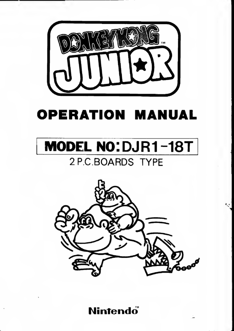
Nintendo Donkey Kong Junior DJR1-UP User manual

OPERATION MANUAL
MODEL no: DJR1-UP
2P.C.B0ARDS TYPE
Nintendo"

WARNING
This equipment generates, uses and can radiate radio frequency
energy and if not installed and used in accordance with the inst-
ructions manual, may cause interference to radio communications.
As temporarily pennitted by regulation it has not been tested
for compliance with the limits for Class Acomputing devices
pursuant to Subpart Jof Part 15 of FCC Rules, which are designed
to provide reasonable protection against such interference.
Operation of this equipment in aresidential area is likely to
cause interference in which case the user at his own expense will
be required to take whatever measures may be required to correct
the interference.

CONTENTS
1. CAUTIONS
2. SPECIFICATIONS
8. PARTS LIST
CAUTIONS
3. INSTALLATION OF THE MACHINE ^
(1) Cautions on installation ... 3
(2) Earthing of machine 3
4. MAINTENANCE AND INSPECTION
(1) Dismounting of front screen 4
(2) Dismounting of operation panel 4
5. POINTS AND METHODS OF ADJUSTMENT
(1) CPU P. C. Board 5
(2)Adjustment of Semi-Fixed Resistors 6
(3)Video Monitor 7
6. WIRING AND CONNECTION 8
7. NAME OF EACH PART
(1) Body 9
(2) Operation Panel Assembly 11
12
1. P. C. Board should not be exposed direct to the sun. Direct
sunshine is very harmful to LSI (memory element).
2P. C. Board to be stored or transported should be wrapped by
aconductive pouch or aluminum foil, because LSI and IC
used in the machine are semiconductor integrated circuits
of which basic element is MOS-FET.
3When images on the Video Monitor screen are disturbed by
powerful noise or other electrical causes, turn the main
power off once and then on again.
-1-

2. SPECIFICATIONS
Power Consumption
Size
Weight
Number of Player
Number of Junior
Accessories
118W
600(W) X850(D) X1700(H)mm.
100 Kgs.
1or 2person(s)
3-6 (Adjustable)
Operation Manual
Key for Back Door
Key for Coin Box Door
Fuse
1copy
2pes.
2pes.
4pes.
100-- 120V :5A X1, 4A X2, 0.3A X1
220- 240V :4A X2, 3A X1, 0.3A X1
NOTE: Specifications are subject to change for improvement without notice.
-2-

3. INSTALLATION OF THE MACHINE
3-1 Cautions on installation
(1
(2
(3
(4
(5
(6
(7
The power cord of the machine should not be connected to awall
outlet together with large load unit (^) such as motor ,cooler, etc.
Turn the power off before setting and removing the P.C.Board
and connectors. Carefully handle them.
Do not touch IC ,LSI and other electronic parts on P.C. Board.
Do not use atester or the like on th^m. (They may be damaged
by the inner voltage of the instruments.)
When exchanging afuse, use anew one of the prescribed capacity.
The machine should be installed where it is not hot, keeping away
from aheating appliance and direct sunshine
.
The machine should be installed where it is not wet and dusty.
Do not touch the inside of the video monitor which has high
tension units. Inform service station, if necessary.
3-2 Earthing of machine
(1) When the machine is installed in awet place, it should be
grounded to avoid accident by an electric shock.
a)Connect an earthing wire to the earthing terminal of the machine
b) The opposite end of the
earthing wire should be
connected to an earthing
bar which is firmly inserted
into the ground
.
(2)Cautions
a
)
Do not connect the earthing
wire to awater pipe, because
polyvinyl-choloride pipes
are sometimes used in the
water lines and, if so, the
electronic continuity is cut
at the points .
b) Do not connect the earthing
wire to the gas pipe abso-
lutely .That is very danger
ous .
-3-

4. MAINTENANCE AND INSPECTION
4-1 Dismounting of front screen
Opening the back door, pull
the front screen clamp
which is mounted under the
top plate .Pull the front
screen upward while pushing
and then puH toward you.
Front Screen Clamp
Front
Screen
Operation
Panel
Front
Door
4-2 Dismounting of operation
panel
To dismount the operation
panel for maintenance or
inspection of the Contro'l
Unit or Micro Switch ,open
the front door and unfasten
the fastener -
Fastener
-4-

5. POINTS AND METHODS OF ADJUSTMENT
5-1 CPU P. C. Board
The number of Junior ,score level, the number of
coin and type of machine c^n be set with the switches
on CPU P.C.Board according to the diagram below.
L
ODJRl-CPU O
SW1
V234
F'[
5
:N
b78
ABCDEH
Number of
Junior
3
4
5
6
AB
Score Level for
extra Junior
10,000 points
15,000 points
20,000 points
25,000 points
OFF
ON
OFF
ON
OFF
OFF
ON
ON
C
Coinage
1coin /I play
1coin /2 plays
1coin /3 plays
1coin /4 plays
2coins/1 play
3coins/1 play
4coins/1 play
5coins/l play
D
OFF
ON
OFF
ON
OFF
OFF
ON
ON
H
Table/Upright
Table
Upright
OFF
OFF
OFF
OFF
ON
ON
ON
ON
OFF
ON
OFF
ON
OFF
ON
OFF
ON
OFF
OFF
ON
ON
OFF
OFF
ON
ON
.
OFF
ON
NOTE :Keep the switch Halways at the ON position
-5-.I'm

5-2 Adjustment of Semi-Fixed Resistors
VIDEO P.C. Board
Semi-fixed resistors, VRl and VR2 on VIDEO P.C. Board are used to adjust video
monitor screen.
OiiO
VRl VR2
DJRl-VIDEO
VIDEO P.C. Board
VRl 50Kn 1/3W top type
white knob
/""^ Turn right to move
V\l image downward.
VR2 50KI2 1/3W top type
white knob f^. lurn right to move
^^image leftward
-6-

5-3 Video Monitor
V-SIZE
V-HOLD
H-CENT
BRIGHT
SOUND VOLUME
Fuse, 4A
H-HOLD
Video Monitor
Main P.C. Board
Fuse 0.3A
NOTE :Do not touch the inside of the Video Monitor in which many parts are supplied
with high tension.
-7-•*

6.WIRING AND CONNECTION
Ci NJ —
nnnnnn ii nnnnnynn
\7
to Mo(O wJo> C7 uro _, olO 00 ^oo> ACO N) ->
X
H
Crt
O
Z
a
1
o
z
o+
<
en
m
c?
^
i<
Oo
z
oCD
(_
C
"0
cn
c
8
z
01
c
CD
c
c
CD
r
m
c
CO
X
s
-1
Is}
5
1
<+
ro
<
+
<
4-
<a
z
oo
z
o
N<X£<cH « :d T3 z£r^L- I-n noow>(/)
o
r
a
m
X
z
t/)
o
m
O
z
oa
z
oo
o
c
m
<
O
s
3^o
z
om
<
m
>
z
c
>
z
8
>
z
c
0
>
z>
z
s
5
D
<
m
X
§
z
1
<+
<
+
<+
<o
z
ao
z
o
oo-ooo-o-o-o-o-o—9-9-9-9<?^>9S^S>^
01(0
g|-0
PS O
»01 r=
ir(C 1- I
6-60-660000
looo-sjoiui^wro-'
-+- I++++55g
K) moi m—-* ^
A<<<hO M
1'
000
(O
O
"0 Xs
<OO O O I
ZZZ Z m
Olb »»! d(9 ^
ooo-ooooo-oo
17 C7 u<
<<<
wro —r'
O
r
o
5" i
II
n
00-000-00-0-0<>6-6"6-6^06-0-00-|
—'(DOO^OiOI^WN)—'-••OOO^OIW-^WISJ-*
oo
y1\1
D
I
<
O
m
O
<
O
m
o
o
3] J3
01 o
o
<
S>SSSl
o
<
lioa
rrmxxmn
53
00 OD
03
3
-8-

7. NAME OF EACH PART
(1) Body
01-24 01-01-01
01-01-
01-33
01-84
01-33
01-02-01
01-02
—9—>

01-01-05
19-01-01 or
09-01-01
19-01-03 or
09-01-03
-10-

(2) Operation Panel Assembly 23-50 4Way Control Lever A'ssy
01-01-
•'
01-70
23-29
01-41 C
23-31
23-32
-11 -
s-

8. PARTS LIST
1. DJR-Body
No. Name of Parts Q'ty Remarks FOB Japan
per pc.
DJRU-0 1-0 1-01 Body
DJRU-0 1-0 1-02 Transformer Base 4
DJRU-0 1-0 1-03 Cash Box %
DJRU-0 1-0 1-04 Control Lever Ass'y Base
DJRU-01-01-05 Back Door
DJRU-0 1-02 Coin Selector T
DJRU-0 1-02-01 Coin Switch T
DJRU-0 1-03 Back Door Lock
DJRU-0 1-04 Front Door Lock
DJRU-0 1-08 Power Cord
DJRU-01-10 Strain Relief Bushing T
DJRU-01-11 Game Counter T
DJRU-51-12 TKG4 P.C.Board Mountmg
Bracket
DJRU-01-13 P.C.Board Support 16
DJRU-01-22 Operation Panel
DJRU-51-23 Front Screen
DJRU-0 1-24 Name Plate
DJRU-0 1-28 Front Door Ass'y
DJRU-0 1-29 Fluorescent Lamp Ass'y
DJRU-0 1-30 Caster 2
DJRU-01-31 Operation Panel Ass'y
Fastener (A)
2
DJRU-0 1-33 Service Switch 1T
DJRU-01-39 Control Lever Ass'y
Mounting Plate
1
DJRU-0 1-41 Control Lever Knob 1
DJRU-0 1-43 Speaker 1
DJRU-01-53 Front Screen Frame (Lower)
DJRU-0 1-5 5Operation Panel Ass'y
Fastener (B)
.2
DJRU-0 1-64 Service Switch Bracket
DJRU-0 1-65 Strain Relief Bushing Plate
DJRU-01-67 Blind Cardboard (Large)
DJRU-0 1-68 Blind Cardboard (Small)
DJRU-01-70 Control Knob Plate
DJRU-56-00 VIDEO P.C.Board (DJRl -VIDEO)
DJRU-57-00 CPU P.C.Board (DJRl-CPU)
DJRU-08-00 (PP-7A) Power P.C.Board T
DJRU- 18-01 (PP-7B) Power P.C.Board T
-12- %

No. Name of Parts
1
Q'ty Remarks FOB Japan
per pc.
DJRU-09-01-01 (PT-8A) Power Transformer
DJRU- 19-0 1-01 (PT-821B) Power Transformer
DJRU-09-01-02 2P I'able Tap %
DJRU-09-01-03 lerminal Block 1(Sexipolar)
DJRU- 19-01-03 Terminal Block (Quadrupolar)
DJRU- 10-01 Power Switch Ass'y
DJRU- 13-01 lOP CLK Harness Connector T
DJRU- 13-02 2P Counter Harness Connector
DJRU- 13-03 9P CPU Harness Connector 1
DJRU- 13-04 3P Coin Harness Connector
DJRU- 13-05 5P Service Harness Connector
DJRU- 13-06 2P Speaker I'V Harness Connector
DJRU- 13-07 4P-750 Audio Harness Connector 1
DJRU-13-10 9P Main Switch Harness
Connector
DJRU- 13- 11 17P Junction Harness Connector
DJRU- 13- 12 SOP Flat Cab e2T
DJRU- 13- 17 2P Speaker Harness Connector
DJRU- 13-28 3P Junction Harness Connector
DJRU- 13-29 4P Main Switch Harness
Connector
DJRU- 13-31 6P-1000 Video Harness Connector
DJRU-20-00 Video Monitor (20-5F)
DJRU-23-10 Micro Switch 3
DJRU-23-12 Switch Button Bracket 3
DJRU-23-13 Control Switch 4T
DJRU-23-14 Blind Plate 11
DJRU-23-16 Bearing Bracket 11
DJRU-23-17 Switch Spacer 41
DJRU-23-19 Schaft 1T
DJRU-23-20 Spring Stopper 1T
DJRU-23-21 Switch Collar 11
DJRU-23-22 Lever Spring 11
DJRU-23-23 ERing 411
DJRU-23-26 Nut Plate 3
DJRU-23-29 Control Knob Collar 11
DJRU-23-31 Switch Button Ass'y (Blue) 2
DJRU-23-32 Switch Button Ass'y (Orange) 1
DJRU-23-34 Pal Nut
DJRU-23-50 4Way Control Lever Ass'y 1T
DJRU-23-51 4Way Guide Plate 11
-13-

2. VIDEO P.C.Board
No. Name of Parts Q'ty Remarks FOB Japan
per pc.
DJR-56-00 VIDEO P.C.Board 1Complete Set (TKG4-1 1-VIDEO)
DJR-56-01
DJR-56-02
IC SN74LS00
IC SN 74LS02
2
3
,_„.-.—
Quadruple 2-Input Positive NAND
Gates
Quadruple 2-Input Positive Nor
Gates
DJR-56-03
DJR-56-04
DJR-56-05
DJR-56-06
DJR-56-07
DJR-56-08
DJR-56-09
IC SN74LS04
IC SN74LS08
ICSN74LS10
IC SN74LS20
IC SN74LS30
IC SN74LS32
IC SN74LS74
6
1
1
4
1
1
4
Hex Inverters '^
Quadruple 2-Input AND Gate
I'ri 3Input NAND Gate
Dual 4-Input Positive NAND Gate
8-Input Positive NAND Gate
Quadruple 2-Input Positive or Gate
Dual D-l'ype Edge-Triggered Flip-
Flop w/Set and Reset
DJR-56-10
DJR-56-11
DJR-56-12
DJR-56-13
DJR-56-14
DJR-56-15
IC SN74LS86
ICSN74LS109
ICSN74LS123
ICSN74LS139
ICSN74LS157
ICSN74LS161
7
1
2
1
14
4
Quadruple 2-Input Executive OR
Gate
Dual J-K Positive Edge-Triggered
Flip-Elops with Preset and Clear
Dual Retriggerable Single Shot
Dual 2-to 4-Line Decoder/Demulti-
plexer
Quadruple 2-Line to 1-Line Data
Synchronous Presettab e4-Bit Binary
Counter w/Direct Reset
DJR-56-16
DJR-56-17
DJR-56-18
DJR-56-19
DJR-56-20
DJR-56-21
DJR-56-22
ICSN74LS163
ICSN74LS174
ICSN74LS175
IC-SN74LS245
IC SN74LS273
IC SN74LS283
IC SN74LS299
2
2
2
4
8
6
4-Bit Binary Counter with Synchro-
nous clear
Hex D-Type Fhp-F op w/Reset RAM
Quadruple D-Type Flip-Flop w/Reset
Octal 3-State Bus Transceivers
Octal D-FFS
4Bit Binary Full Adder
8Bit Bidirectional Universal Shift/
Storage
--—_—^'"-^
DJR-56-23
DJR-56-24
DJR-56-25
DJR-56-26
DJR-56-27
DJR-56-28
DJR-56-29
DJR-56-30
IC SN74LS367
IC SN74LS373
IC SN74LS377
ICSN74S161
ICMB10105
ICMB10116
IC MB 101 24
ICMB10125
2
2
1
3
1
1
4
3
Hex Bus Driver w/3 State Output
Octal 3-State D-Latches
Octal D-Type Flip-Flops
Schotkey 4-Bit Binary Counter with
Direct Clear
Triple 2-3-2-Input OR/NOR Gates
Triple Line Receivers
Quadruple 11L-to-ECL Translators
Quadruple ECL-to-TTL Translators
DJR-56-31
DJR-56-32
DJR-56-33
ICMB10136
IC2716
IC MB7074
1
4
2
Universal Hexadecimal Counter
2048 X 8 Bit EP-ROM
ECL-RAM (MBM 10422) with
Radiator Fin
14- %

No. Name of Parts
1
Q'ty Remarks FOB Japan
per pc.
DJR-56-34 IC 2732 1
^4096 X8Bit EP-ROM
DJR-56-35 ICMB93419 164.x 9Bipolar RAM
DJR-56-36 ICMB8114 21024 X4-Bit Static MOS RAM
DJR-56-37 ICMB8148L55 21024 X4-Bit Static RAM.
DJR-56-38 IC24S10 1256 X4-Bit Bipolar P-ROM
DJR-56-39 Resistor Array 4RNSA-09P-551J 8-device 51012
DJR-56-40 Resistor Array 1RNSA-09P-102J 8-device Ikn
DJR-56-41 Variable Resistor 250kn 1/3W
DJR-56-42 Resistor (Carbon) 2lOkfi 1/4W±5%
DJR-56-43 Resistor (Carbon) 12 5ion 1/4W±5%
DJR-56-44 Resistor (Carbon) 215kn 1/4W±5%
DJR-56-45 Resistor (Carbon) 42.2kn 1/4W±5%
DJR-56-46 Resistor (Carbon) 24.7kn 1/4W±5%
DJR-56-47 Resistor (Carbon) 122kn 1/4W±5%
DJR-56-48 Resistor (Carbon) 127kJ2 1/4W±5%
DJR-56-49 Resistor (Carbon) 24 lkJ2 1/4W±5%
DJR-56-50 Electrolytic Capacitor 2.220AtF 16V
DJR-56-51 Electrolytic Capacitor 2ImF 50V
DJR-56-52 Ceramic Capacitor 147pF 50V
DJR-56-53 Ceramic Capacitor 128 O.OImF 50V
DJR-56-54 Ceramic Capacitor 133pF 50V
DJR-56-55 Ceramic Capacitor 210pF50V
DJR-56-56 Ceramic Capacitor 4220pF 50V
DJR-56-57 Ceramic Capacitor 268pF 50V
DJR-56-58 Ceramic Capacitor 1330pF 50V
DJR-56-60 Polyester Eilm Capacitor 1lOOOpF 50V(102kz)
DJR-56-61 Polyester Film Capacitor 10.1a(F50V
DJR-56-62 Polyester Film Capacitor 10.022/iF 50V
DJR-56-63 Transistor 22SC1215-R/S/T
DJR-56-64 Crystal Oscillator 161.44MHz (HC-18U)
-15- 'i-

3. CPU P.C.Board
No. Name of Parts Q'ty Remarks FOB Japan
per pc.
DJR-57-00 CPU P.C.Board 1Complete Set (TKG4-1 1-CPU)
DJR-57-01
DJR-57-02
DJR-57-03
DJR-57-04
DJR-57-05
DJR-57-06
IC SN74LS00
IC SN74LS02
IC SN74LS04
IC SN74LS08
IC SN74LS32
IC SN74LS74
2
2
6
I
1
2
Quadruple 2-Input Positive NAND
Gates*
Quadruple 2-Input Positive NOR
Gate
Hex Inverters ^
Quadruple 2-Input AND Gates
Quadruple 2-Input Positive OR
Gate
Dual D-Type Edge-Triggered Flip-
Flop w/Set and Reset
DJR-57-07
DJR-57-08
DJR-57-09
DJR-57-10
DJR-57-1
1
DJR-57-12
DJR-57-1
3
IC SN74LS86
ICSN74LS123
ICSN74LS125
ICSN74LS132
ICSN74LS138
ICSN74LS139
ICSN74LSI57
1
4
1
1
5
1
1
Quadruple 2-input Exclusive
OR Gate
Dual Retriggerable Single Shot
Quadruple 3State Bus Buffers
Quadruple 2-Input NAND Schmit
Triggers
3-to-8-Line Decoder/Demultiplexer
Dual 2-ta-4-Line Decoder/Demulti-
plexer
2-to-l-Line Data Selectors/Multi-
plexers
DJR-57-1
4
DJR-57-1 5
DJR-57-1
7
DJR-57-1
8
DJR-57-1
9
DJR-57-20
DJR-57-21
ICSN74LS164
ICSN74LSI74
IC SN74LS240
IC SN74LS245
IC SN74LS259
IC SN74LS367
ICSN74LS373
2
3
4
1
3
6
3
8-Bit Serial-In Parallel-Out Shift
Register
Hex D-Type Flip-Flop
Octal Buffer/Line Driver/Line Receiver
w/3-State
Octal 3-State Bus Transceivers
8-Bit Addressable Latches
Hex Bus Driver w/3 State Output
Octal 3-State D-latches
DJR-57-22
DJR-57-23
DJR-57-24
DJR-57-25
DJR-57-26
DJR-57-27
DJR-57-28
DJR-57-29
IC SN74LS629
ICMB8114
IC 2764
IC Z80A
IC24S10
IC 8257-5
IC 2732
IC MB8884
3
6
3
1
2
Voltage Control Oscillators
1024 X4-Bit Static MOS RAM
8192 X8-Bit EP ROM
8-Bit Microprocessor
Bipolar ROM 256 x4-Bit
DMA Controller
4096 X8-Bit EP ROM
8-Bit Microprocessor
DJR-57-30
DJR-57-31
DJR-57-32
DJR-57-33
ICMB3614
IC3192
IC DAC08CQ
(C CD4020B
Lower Power Quadruple Operational
Amplifiers
Custom
8-Bit Digital-to-Analog Converter
14-Stage Binary Ripple Counter
-16-

No. Name of Parts Q'ty Remarks FOB Japan
per pc.
DJR-57-34 Transistor 42SC1815
DJR-57-35 Transistor 12SC1384-R
DJR-57-36 Transistor 42SC8.28-P/Q
DJR-57-37 Transistor 22SA564-P/Q/R
DJR-57-38 Diode 10 IS953
DJR-57-39 Diode 1W03B -»
DJR-57-40 Dip Switch 1B-8A
DJR-57-41 Aluminium Electrolytic Capac-
itor
2470mF 16V
DJR-57-42 Electrolytic Capacitor 1220a(F 16V
DJR-57-43 Electrolytic Capacitor 133m F16V
DJR-57-44 Electrolytic Capacitor 31/iF 50V
DJR-57-45 Electrolytic Capacitor 14JnF 50V
DJR-57-46 Electrolytic Capacitor 23.3/iF 50V
DJR-57-47 Electrolytic Capacitor 15 IOmF 16V
DJR-57-48 Electrolytic Capacitor 2IOOaiF 16V
DJR-57-49 Electrolytic Capacitor 347m F16V
DJR-57-50 Ceramic Capacitor 30.068mF 25V
DJR-57-51 Ceramic Capacitor 82 O.OImF 50V
DJR-57-52 Ceramic Capacitor 10.022mF 25V
DJR-57-53 Ceramic Dapacitor 222pF 50V
DJR-57-54 Ceramic Capacitor 20.47m F50V
DJR-57-56 Polyester Film Capacitor 1O.OImF 50V
DJR-57-57 Polyester Film Capacitor 10.22mF 50V
DJR-57-58 Polyester Film Capacitor 10.022mF 50V
DJR-57-59 Polyester Film Capacitor 10.0047m'F 50V
DJR-57-60 Polyester Film Capacitor 20.12mF50V
DJR-57-61 Polyester Film Capacitor 10.056mF 50V
DJR-57-62 Tantalum Capacitor 3IOmF 16V
DJR-57-63 Tantalum Capacitor 14.7mF 16V
DJR-57-64 1antalum Capacitor 222m F 16V
DJR-57-65 Series Resistor Array 3Ikn PNSA-09P-102J
DJR-57-66 Parallel Resistor Array 668n PNSB-08P-680J
DJR-57-67 Series Resistor Array 14Jkn PNSB-09P-472J
DJR-57-68 Resistor (Carbon) 647kn 1/4W±5%
DJR-57-69 Resistor (Carbon) 12kn 1/4W±5%
DJR-57-70 Resistor (Carbon) 64.1kn 1/4W±5%
DJR-57-71 Resistor (Carbon) 910kr2 1/4W±5%
DJR-57-72 Resistor (Carbon) 7lOOkn 1/4W±5%
DJR-57-73 Resistor (Carbon) 15 \kn 1/4W±5%
DJR-57-74 Resistor (Carbon)
——25.6kJ2 1/4W±5%
-17 -
1

No. Name of Parts Q'ty Remarks FOB Japan
per pc.
DJR-57-75 Resistor (Carbon) 1120n 1/4W±5%
DJR-57-76 Resistor (Carbon) 1150J> 1/4W±5%
DJR-57-77 Resistor (Carbon) 220Kn 1/4W±5%
DJR-57-78 Resistor (Carbon) 1150KJ2 1/4W±5%
DJR-57-79 Resistor (Carbon) 130Kn 1/4W±5% ^
DJR-57-80 Resistor (Carbon) 143Kn 1/4W±5% 1
DJR-57-81 Resistor (Carbon) 113Kn 1/4W±5%
DJR-57-83 Resistor (Carbon) 568n 1/4W±5%
'^
DJR-57-84 Resistor (Carbon) 7330n 1/4W±5%
DJR-57-85 Resistor (Carbon) 233kn 1/4W±5%
DJR-57-86 Resistor (Carbon) 4220n 1/4W±5%
DJR-57-87 Resistor (Carbon) 547on l/4W+5%
DJR-57-88 Resistor (Carbon) 1680n 1/4W±5%
DJR-57-89 Resistor (Carbon) 4lOOn 1/4W±5%
DJR-57-90 Resistor (Carbon) 1200n 1/4W±5%
DJR-57-91 Crystal Oscillator 1HC-18U- 182 (6.000MHz)
-18-
Table of contents
Other Nintendo Arcade Game Machine manuals
Popular Arcade Game Machine manuals by other brands
I.C.E
I.C.E Iceball Pro Assembly guide & user's manual

Bay-Tek
Bay-Tek Lil Ticket Monster Service manual

Magic Play
Magic Play CAPSULE BOXER Operation manual

Hasbro Gaming
Hasbro Gaming BULLS-EYE ALL quick start guide

Williams
Williams PIN-BOT instruction manual

Barron Games
Barron Games X-Putt Operator's guide

Bob's Space Racers
Bob's Space Racers Puppy Jump Operation manual

Raw Thrills
Raw Thrills Space Invaders Frenzy Operator's manual

Kriss Sport
Kriss Sport Superpunch BOXER user guide

IGS
IGS High Roller Club Operator's manual

PinSound
PinSound RocketCPU WPC89 installation manual

DSM
DSM TIC TAC TOE owner's manual