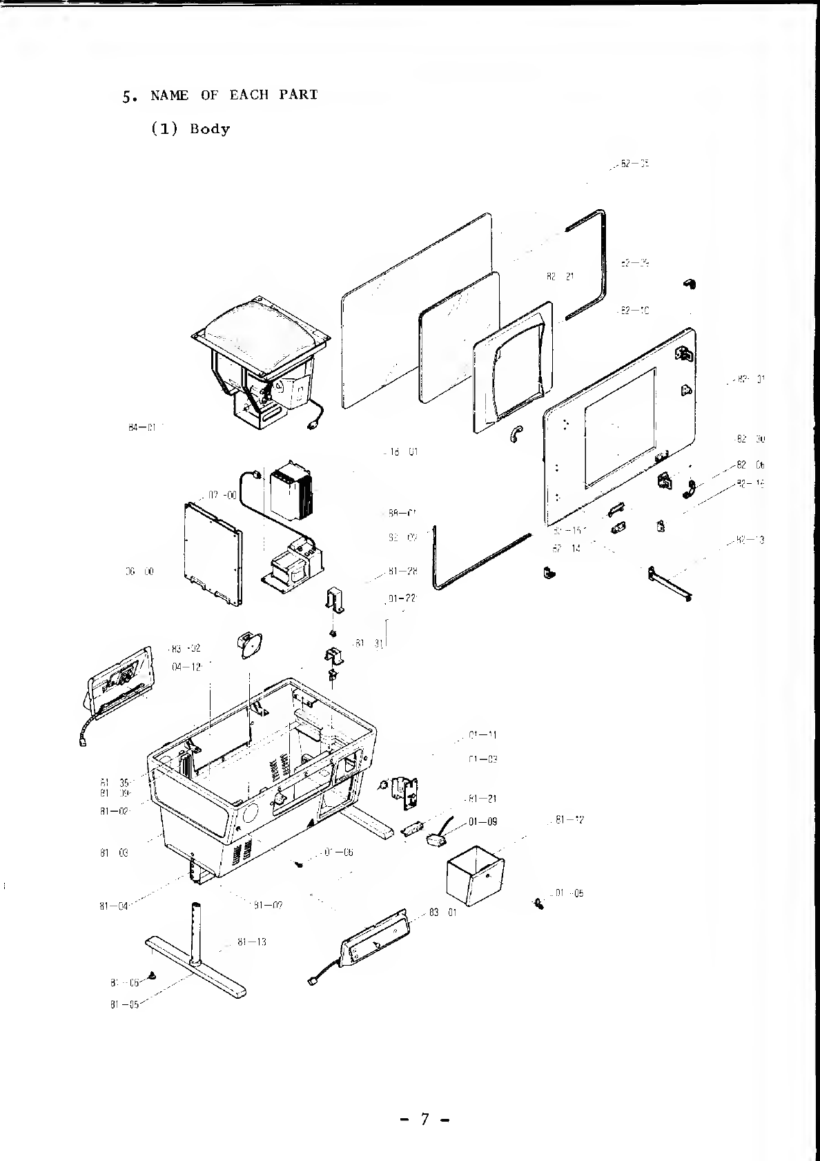
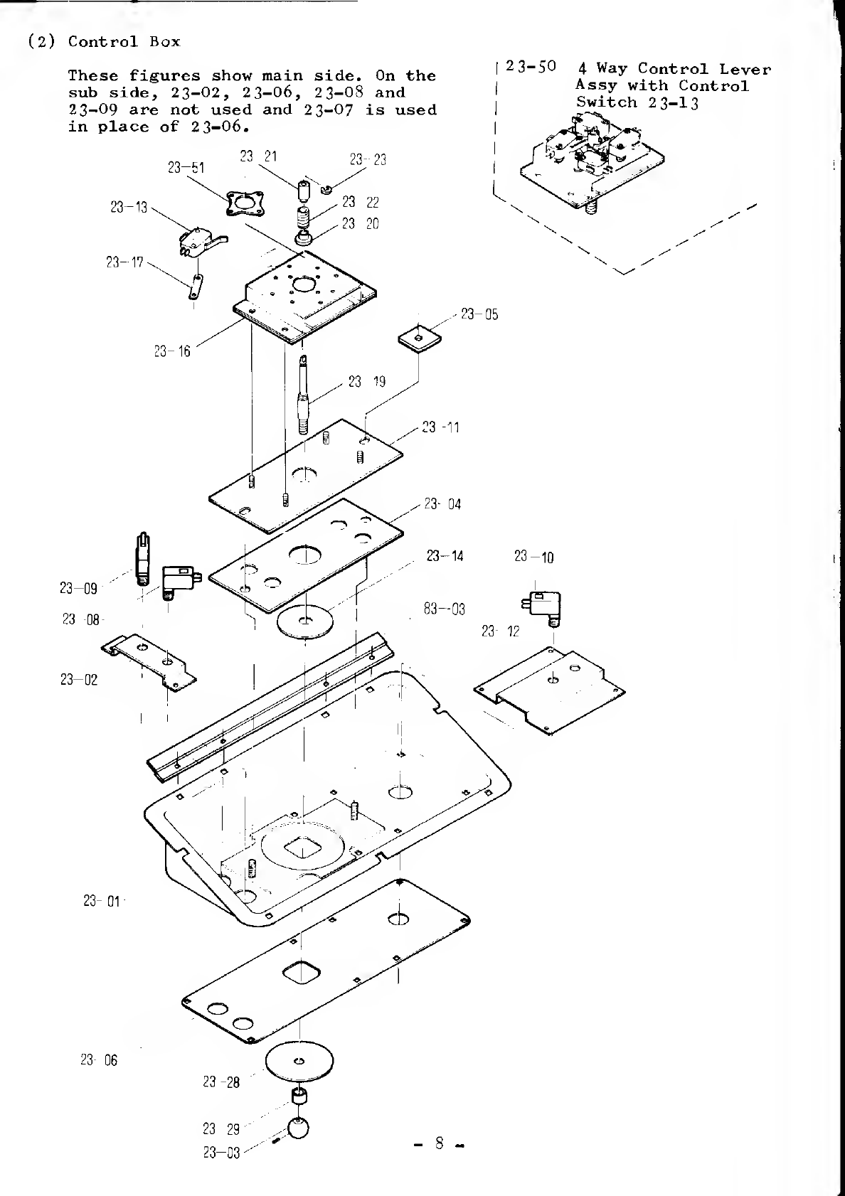
Nintendo DONKEYKONG JUNIOR DJR1-18T User manual
Other Nintendo Arcade Game Machine manuals


Popular Arcade Game Machine manuals by other brands

Universal Space
Universal Space COCONUT BASH Operation manual

Bay-Tek
Bay-Tek EVOLVE installation guide

Global VR
Global VR America's Army Operation & service manual

Atronic
Atronic Cashline installation manual

Universal Space
Universal Space Checky Monkey Operation manual

Bay-Tek
Bay-Tek Skee Ball 1908 Alley Service manual

Aristocrat Technologies
Aristocrat Technologies Mars X Upright Service manual

Family Fun Companies
Family Fun Companies Reactor Parts, Service and Distribution

Universal Space
Universal Space FRUIT MANIA Extreme Operation manual

falgas
falgas CARRUSEL FIESTA user guide

Konami
Konami DanceDanceRevolution Operator's manual

Bay-Tek
Bay-Tek quik drop Service manual

Bandai Namco
Bandai Namco PAC-MAN BATTLE ROYALE CHOMPIONSHIP DELUXE Operation manual

Adrenaline
Adrenaline Flying Tickets Operation & service manual

Swinks
Swinks Stern Pinball Ghostbusters manual

Innovative Concepts in Entertainment
Innovative Concepts in Entertainment MONOPOLY ROLL-N-GO Service manual

jakar
jakar SPEED CARS Operator's manual

Carmelli
Carmelli HAT TRICK NG1015H Assembly instructions