Nippon EMP-3 User manual

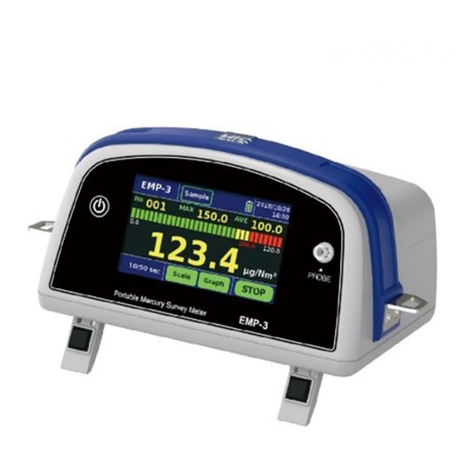
Portable Mercury Survey Meter
EMP-3
INSTRUCTION MANUAL
NIC-TD-0000067-01
NIPPON INSTRUMENTS CORPORATION

Instruction Manual: EMP-3 NIC-TD-0000067-01
Nippon Instruments Corporation
CONTENTS
1. OUTLINE..........................................................................................................................1
SAFETY PRECAUTIONS ......................................................................................... 1
1.1.1 MEANINGS AND EXPLANATIONS OF SYMBOLS ........................................ 1
1.1.2 CAUTIONS CONCERNING INSTALLATION...................................................1
1.1.3 CAUTIONS CONCERNING HANDLING ..........................................................2
1.1.4 CAUTIONS CONCERNING BATTERY..............................................................3
1.1.5 CAUTIONS CONCERNING DISPOSAL ............................................................4
2. OUTLINE OF INSTRUMENT........................................................................................5
SIMPLIFIED EXPLANATION.................................................................................. 5
PRINCIPLE OF MEASUREMENT........................................................................... 6
EXTERNALAPPEARANCE OF INSTRUMENT.................................................... 7
2.3.1 UPPER PART.........................................................................................................7
2.3.2 BOTTOM...............................................................................................................7
2.3.3 FRONT ..................................................................................................................8
3. INSTALLATION ..............................................................................................................9
4. MEASUREMENT...........................................................................................................10
MEASUREMENT FLOWCHART...........................................................................10
NECESSITIES FOR MEASUREMENT.................................................................. 11
ARTICLES RECOMMENDED FOR MEASUREMENT........................................ 11
PREPARATION FOR MEASUREMENT................................................................ 12
4.4.1 CHARGING AND CONNECTION OF BATTERY ...........................................12
4.4.2 CONNECTION OF PROBE................................................................................ 14
4.4.3 WEARING OF INSTRUMENT.......................................................................... 15
OPERATIONAL PROCEDURE FOR MEASUREMENT....................................... 16
4.5.1 STARTUP ............................................................................................................ 16
4.5.2 SETTINGS...........................................................................................................17
4.5.2.1 SETTING OF MEASUREMENT MODE .......................................................17
4.5.2.2 SETTING OF GAS TO BE MEASURED.......................................................18
4.5.2.3 SETTING OF NORMALIZATION CONVERSION PARAMETERS............ 19
4.5.3 MEASUREMENT PROCEDURE.......................................................................21
4.5.3.1 START OF MEASUREMENT......................................................................... 21
4.5.3.2 MEASUREMENT SEQUENCE......................................................................22
4.5.3.3 CHECKING OF DATA....................................................................................24
4.5.3.4 CHECKING OF DRIFTAND INTERFERING COMPONENTS ..................25

Instruction Manual: EMP-3 NIC-TD-0000067-01
Nippon Instruments Corporation
4.5.3.5 TERMINATION OF MEASUREMENT .........................................................27
4.5.4 SHUTDOWN....................................................................................................... 27
MEASUREMENT OF LIQUEFIED NATURAL GAS OR LIQUEFIED
PETROLEUM GAS................................................................................................................ 28
5. CONTROL SOFTWARE............................................................................................... 29
CONSTITUTION OF MENU...................................................................................29
MAIN SCREEN........................................................................................................ 30
MEASUREMENT SCREEN....................................................................................31
5.3.1 NUMERIC SCREEN........................................................................................... 31
5.3.1.1 DESCRIPTIONS OF ICONS........................................................................... 31
5.3.1.2 SCALE CHANGE............................................................................................ 32
5.3.2 GRAPH SCREEN................................................................................................ 33
5.3.2.1 DESCRIPTIONS OF ICONS........................................................................... 33
5.3.2.2 ALTERATIONS OF SCALES (CONCENTRATION AND TIME) ................33
MENU SCREEN.......................................................................................................35
5.4.1 CONSTITUTION OF MENU..............................................................................35
5.4.2 HANDLING OF DATA.......................................................................................36
5.4.2.1 SAVING OF DATA.......................................................................................... 36
5.4.2.2 CHECK DATA.................................................................................................36
5.4.2.3 EXPORT DATA................................................................................................ 39
5.4.2.4 DELETE DATA................................................................................................40
5.4.3 SETTING............................................................................................................. 41
5.4.3.1 MEASUREMENT (1/2)................................................................................... 41
5.4.3.2 MEASUREMENT (2/2)................................................................................... 43
5.4.3.3 INSTRUMENT ................................................................................................46
5.4.4 MAINTENANCE ................................................................................................49
5.4.4.1 GLP...................................................................................................................49
5.4.4.2 REF/SIG VOLTAGE........................................................................................ 50
5.4.4.3 INFORMATION...............................................................................................51
5.4.4.4 GPS................................................................................................................... 52
5.4.4.5 HARDWARE OUTPUT...................................................................................53
5.4.4.6 CALIBRATION/ MANUFACTURER.............................................................54
MEASUREMENT DATA......................................................................................... 55
5.5.1 OUTPUT DATA................................................................................................... 55
5.5.2 INSTANTANEOUS VALUE............................................................................... 55
5.5.3 AVERAGE VALUE............................................................................................. 55
6. MAINTENANCE............................................................................................................56

Instruction Manual: EMP-3 NIC-TD-0000067-01
Nippon Instruments Corporation
DAILY INSPECTION...............................................................................................56
RECOMMENDED REPLACEMENT COMPONENTS..........................................57
YEARLY INSPECTION........................................................................................... 57
ERRORS AND WARNINGS....................................................................................58
MAINTENANCE WORK ........................................................................................60
6.5.1 REPLACEMENT OF ZERO FILTER................................................................. 60
6.5.2 REPLACEMENT OF PROBE COMPONENTS.................................................62
6.5.3 ADJUSTMENT OF OPTICAL SYSTEM........................................................... 64
6.5.3.1 AUTOMATIC ADJUSTMENT........................................................................64
6.5.3.2 MANUALADJUSTMENT.............................................................................. 65
6.5.4 SIMPLIFIED CALIBRATION............................................................................ 68
6.5.4.1 PROCEDURE FOR PREPARATION OF STANDARD GAS ........................68
6.5.4.2 CALCULATION PROCEDURE FOR STANDARD GAS CONCENTRATION
69
6.5.4.3 MERCURY QUANTITY IN STANDARD GAS............................................. 70
6.5.4.4 CALIBRATION PROCEDURE.......................................................................71
7. DETAILED SYSTEM SPECIFICATION.................................................................... 73
SPECIFICATION OF EMP-3 MAIN UNIT............................................................. 73
CONTROLAND USER INTERFACE.....................................................................74
EXTERNAL CONNECTION FUNCTION..............................................................74
DIMENSIONS AND WEIGHT................................................................................ 74
POWER SUPPLY ..................................................................................................... 74
STANDARD ACCESSORIES.................................................................................. 75
OPTIONS.................................................................................................................. 75
8. INSTALLATION REQUIREMENTS...........................................................................76
INSTALLATION ENVIRONMENT........................................................................76
MEASURES AGAINST ELECTRIC NOISE .......................................................... 76
OTHER REQUIREMENTS......................................................................................76
9. WARRANTY...................................................................................................................77
WARRANTY PERIOD............................................................................................. 77
WARRANTYTERMS.............................................................................................. 77
10. CAUTIONS CONCERNING DISPOSALOF INSTRUMENT..................................77
11. CONTACTADDRESS ...................................................................................................78

Instruction Manual: EMP-3 NIC-TD-0000067-01
Nippon Instruments Corporation 1
1. OUTLINE
SAFETY PRECAUTIONS
To use this product safely, observe the following precautions.
Nippon Instruments Corporation will not take any responsibility for accidents caused
by a user’s carelessness.
In the case of mishandling, a user may be killed or suffer a serious
injury immediately.
In the case of mishandling, a user may be killed or suffer a serious
injury.
In the case of mishandling, a user may suffer an injury or material
damage is expected.
Although the EMP-3 has drip-proof and dustproof features
(except for sample gas) equivalent to IP63, to obtain precise
and accurate measurement results, it is advisable to avoid
installation in an environment with high temperature and
humidity or with much dust and exposure to rainfall or liquid.
Observe the installation requirements and installation
procedure. Otherwise, a failure may result.
Do not install the instrument within a 10 m radius from another
instrument that generates noise, such as a high output electric
power instrument, high frequency instrument, SCR controlled
machine, emission spectrophotometer or electric welder. Also
be fully careful of static electricity.
When measurements are made with the instrument kept
motionless, install it on a horizontal place with sufficient
strength.
Otherwise, a failure or a minor injury caused by an overturn or a
fall may result.
When carrying the instrument, put the belt on the shoulder
opposite from the instrument, attach the waist belt too.
Otherwise, a failure or an injury caused by a fall may result.
Make sure that the probe to be used is not wet or dirty.
When attaching the probe or replacing a component, take care
not to damage the probe connector.
Danger
Warning
Caution
Caution

Instruction Manual: EMP-3 NIC-TD-0000067-01
Nippon Instruments Corporation 2
This instrument does not have explosion-proof structure.
Before measuring liquefied natural gas or liquefied petroleum
gas, be sure to collect some into a Tedlar Bag. Please measure
them in non-explosion-proof areas.
Do not let liquid such as water splash the instrument. Never
operate the instrument with a wet hand. Otherwise, an electric
shock, a short circuit of an electronic circuit or a failure caused
by corrosion may result.
Do not disassemble or modify the product without permission.
Otherwise, a failure may result. For inspection or repair,
consult with our agent or service department.
Use the instrument after reading this document carefully.
Otherwise, a failure caused by an operational mistake may
occur.
Observe the range of the specification. If the instrument is used
out of the specification range, a failure may occur.
Do not give a shock to the instrument by dropping, throwing or
the like. The limit of fall height is 3cm.
Do not apply a strong external force to the screen by pushing
strongly, striking or the like.
Do not operate the instrument before the connection of the
probe is completed. Otherwise, fine particles will enter the
instrument and accurate measurements may become
impossible.
Select a probe suitable for a measurement position.
If any time-change component is not replaced, original
performance may not be demonstrated.
For data output, we recommend the supplied USB memory.
Although it is also possible to use a USB memory other than
the supplied one, data output may fail or data in the USB
memory may be damaged depending on a type.
Gas after a measurement is discharged from the outlet. When
measuring liquefied natural gas or liquefied petroleum gas, use
the instrument in a draft chamber or connect the outlet and
draft chamber or exhaust duct using a tube to discharge the gas.
Warning
Caution

Instruction Manual: EMP-3 NIC-TD-0000067-01
Nippon Instruments Corporation 3
Observe the following conditions. Otherwise, the battery may
ignite or explode.
●Do not use a battery other than the dedicated one.
●Charge the battery using the supplied battery charger.
When charging, do not apply a voltage out of the power
supply range to the battery charger.
●Charge and keep the battery indoors and at the normal
temperature (0C to 45C).
●Do not wet the battery with water or expose it to a humid
environment.
●Do not disassemble or modify the battery.
●Do not give a shock to the battery by dropping, throwing or
the like.
●Connect the battery to the analyzer or battery charger in the
right direction.
●If an abnormality of the battery such as a deformation,
heating or liquid leakage is found, stop using it
immediately.
●Do not charge forcibly or use the battery when its lifetime
has expired.
Wipe off dust attached around the power plug and terminals.
Otherwise, a fire may result.
The battery life decreases because of the self-discharge even
when the battery is not used. Check the remaining of battery
life before a measurement. When the battery has been left
unused, charge it before the use.
The battery is a consumable. The maximum capacity
deteriorates as charging is repeated. Replace it with a new one
early. (After 300 times, the capacity deteriorates to
approximately 60%.)
When charging is not completed even after 5 hours or more,
stop it promptly. The lifetime of the battery has possibly
expired, or the battery charger may be faulty.
When the battery has been damaged or liquid leakage has
occurred, do not charge it.
When discarding the battery the lifetime of which has expired,
cover the terminals with insulating tapes or the like, and then
dispose of the battery appropriately according to the
regulations or rules of the local government.
Warning
Caution

Instruction Manual: EMP-3 NIC-TD-0000067-01
Nippon Instruments Corporation 4
If the instrument is discarded inadequately, environmental
pollution or personal damage may result.
Dispose of it according to the regulations or rules of the local
government.
Caution

Instruction Manual: EMP-3 NIC-TD-0000067-01
Nippon Instruments Corporation 5
2. OUTLINE OF INSTRUMENT
SIMPLIFIED EXPLANATION
EMP-3 is a portable mercury survey meter that is battery-driven, compact, light and
portable.
Main use is measurement of mercury concentration in working environment and in
petroleum gas. When option is connected, it is also possible to measure liquid samples and
high concentration mercury gas.
Complex setup and operation are unnecessary and even a beginner can measure mercury
easily.
Data is automatically saved in the instrument and can be checked and extracted to a USB
memory after a measurement.

Instruction Manual: EMP-3 NIC-TD-0000067-01
Nippon Instruments Corporation 6
PRINCIPLE OF MEASUREMENT
When a measurement is started, gas in the working environment (hereinafter referred to as
sample gas) is always taken in through the probe till the end of the measurement.
Flowchart
The detector (Ref) measures the voltage (reference voltage) used as the standard, and the
detector (Sig) measures the lamp voltage (signal voltage) after passage through the cell.
The voltages change as the temperature in the instrument changes. That change is detected
using the reference voltage. When mercury gas enters the cell, light is absorbed and the
detected signal voltage decreases. At that time, the absorbance is measured at 253.7 nm,
which is the first absorption wavelength band of mercury.
A mercury concentration is calculated from the variation of the reference voltage and the
decrease of the signal voltage.
A measurement consists of the cycle of the ZERO check and mercury concentration
measurement.
ZERO Check
Sample gas passes through the ZERO filter that adsorbs mercury, and
gas that does not contain mercury (hereinafter, referred to as ZERO
gas) is led to the absorption cell.
From the mercury absorbance measured at that time, the baseline of a
mercury concentration is determined.
Mercury
Concentration
Measurement
Gas that has not passed through the ZERO filter is led to the
absorption cell.
A mercury absorbance at that time is measured.
By calculating a relative value from the ZERO check and mercury concentration
measurement, a precise and accurate mercury concentration is obtained without receiving
interference by interfering components.
By connecting an optional apparatus instead of the probe, various mercury analyses
become possible. For details, see the specification documents and instruction manuals of
optional apparatus.
Mercury
Lamp
Detector
(Sig)
Detector
(Ref.)
Absorption
Cell
ZERO Filter
Three Way Valve
Air Pump
Temperature Sensor
Pressure Sensor
Probe
Inlet
Outlet
Mercury Concentration Measurement
ZERO Correction

Instruction Manual: EMP-3 NIC-TD-0000067-01
Nippon Instruments Corporation 7
EXTERNAL APPEARANCE OF INSTRUMENT
No.
Name
Description
1
Power Button
Turns on or off the instrument power.
2
LCD Unit With
Touch Screen
A measurement concentration can be displayed and measuring conditions can
be set.
3
Inlet
Connection for the probe and main unit.
4
Probe
A filter is connected to the tip to remove fine particles in sample gas.
No.
Name
Description
1
Tilting Foot
Used to put the instrument horizontally
2
ZERO Filter
Mercury adsorption filter
1
2
3
4
2
1

Instruction Manual: EMP-3 NIC-TD-0000067-01
Nippon Instruments Corporation 8
No.
Name
Description
1
Outlet
Discharge of gas after a measurement
2
External Interface
It is possible to connect a USB memory and RS-232C and external
contact input/output cables.
3
USB Memory Connection
It is possible to connect a USB memory to export data.
4
RS-232C Cable Connection
It is possible to connect an RS-232C cable. This is used to connect an
option or for a similar purpose.
5
GPIO (External Contact
Input/Output)
It is possible to communicate with an external device using external
contact input/output.
6
Battery
Battery exclusively for the EMP-3
1
2
3
4
5
6
1

Instruction Manual: EMP-3 NIC-TD-0000067-01
Nippon Instruments Corporation 9
3. INSTALLATION
Although the EMP-3 has drip-proof and dustproof features
(except for sample gas) equivalent to IP63, to obtain precise
and accurate measurement results, it is advisable to avoid
installation in an environment with high temperature and
humidity or with much dust and exposure to rainfall or liquid.
Observe the installation requirements and installation
procedure. Otherwise, a failure may result.
Do not install the instrument within a 10 m radius from another
instrument that generates noise, such as a high output electric
power instrument, high frequency instrument, SCR controlled
machine, emission spectrophotometer or electric welder. Also
be fully careful of static electricity.
When measurements are made with the instrument kept
motionless, install it on a horizontal place with sufficient
strength.
Otherwise, a failure or a minor injury caused by an overturn or
a fall may result.
To install the instrument on a desk or the like, stand the tilting feet and install the instrument
as shown below:
Caution

Instruction Manual: EMP-3 NIC-TD-0000067-01
Nippon Instruments Corporation 10
4. MEASUREMENT
MEASUREMENT FLOWCHART
A measurement is made according to the following flowchart.
* Double frames indicate processes that the operator carries out.
Turning On of Power
MENU-Setting:Checking and Alteration of Settings
(Measurement Mode, Gas to Be Measured, Temperature, Atmospheric Pressure)
Adjust
(Initial Adjustment of
Instrument)
Measurement of Mercury
Concentration
Repetition
Turning Off of Power
START:Measurement Start
Zero Check
(Checking of Baseline)
STANDBY
(Warming Up for 10 Min.)
STOP:Measurement Stop
MENU-Export Data:Extraction of Data
Remeasurement

Instruction Manual: EMP-3 NIC-TD-0000067-01
Nippon Instruments Corporation 11
NECESSITIES FOR MEASUREMENT
(1) Battery
(2) Battery Charger
(3) Probe
(4) USB Memory
ARTICLES RECOMMENDED FOR MEASUREMENT
(1) Spare Battery
(2) Long Probe
(3) Tedlar Bag (used to collect sample gas and to prepare standard gas)
(4) Kit for Calibration CK-1 (for standard gas preparation)

Instruction Manual: EMP-3 NIC-TD-0000067-01
Nippon Instruments Corporation 12
PREPARATION FOR MEASUREMENT
Observe the following conditions. Otherwise, the battery may
ignite or explode.
●Do not use a battery other than the dedicated one.
●Charge the battery using the supplied battery charger.
When charging, do not apply a voltage out of the power
supply range to the battery charger.
●Charge and keep the battery indoors and at the normal
temperature (0C to 45C).
●Do not wet the battery with water or expose it to a humid
environment.
●Do not give a shock to the battery by dropping, throwing or
the like.
●Connect the battery to the analyzer or battery charger in the
right direction.
●If an abnormality of the battery such as a deformation,
heating or liquid leakage is found, stop using it
immediately.
●Do not charge forcibly or use the battery when its lifetime
has expired.
Wipe off dust attached around the power plug and terminals.
Otherwise, a fire may result.
The battery life decreases because of the self-discharge even
when the battery is not used. Check the remaining of battery
life before a measurement. When the battery has been left
unused, charge it before the use.
The battery is a consumable. The maximum capacity
deteriorates as charging is repeated. Replace it with a new one
early. (After 300 times, the capacity deteriorates to
approximately 60%.)
When charging is not completed even after 5 hours or more,
stop it promptly.
The lifetime of the battery has possibly expired, or the battery
charger may be faulty.
When the battery has been damaged or liquid leakage has
occurred, do not charge it.
It is unnecessary to charge the battery each time it is used. However, when it has been left
unused for some period of time or the remaining battery life is insufficient at a startup, use
a spare battery or detach the battery and charge it using the dedicated battery charger.
* The continuous operation of the EMP-3 is possible for five hours and a half using a
new, fully charged battery.
It takes approximately five hours to charge an empty battery fully.
Warning
Caution

Instruction Manual: EMP-3 NIC-TD-0000067-01
Nippon Instruments Corporation 13
(1) Connect the battery to the dedicated battery charger, and charge it. Please set the
battery charger to 1.0A.
(2) When the charging is completed, the color of the charging lamp of the battery charger
changes from red to green.
(3) Detach the battery fromthe battery charger and attach the battery to the instrument main
unit.
Open

Instruction Manual: EMP-3 NIC-TD-0000067-01
Nippon Instruments Corporation 14
Make sure that the probe is not wet or dirty.
Do not operate the instrument before the connection of the
probe is completed. Otherwise, fine particles will enter the
instrument and accurate measurements may become impossible.
When attaching the probe, take care not to damage the probe
connector.
The probe and probe filter are consumables. Replace them
periodically.
Select a probe suitable for a measurement position.
(1) Connect the probe to the inlet.
Caution

Instruction Manual: EMP-3 NIC-TD-0000067-01
Nippon Instruments Corporation 15
Although the EMP-3 has drip-proof and dustproof features
(except for sample gas) equivalent to IP63, to obtain precise
and accurate measurement results, it is advisable to avoid
installation in an environment with high temperature and
humidity or with much dust and exposure to rainfall or liquid.
Observe the installation requirements and installation
procedure. Otherwise, a failure may result.
When carrying the instrument, put the belt on the shoulder
opposite from the instrument, attach the waist belt too.
Otherwise, a failure or an injury caused by a fall may result.
(1) Put the shoulder belt on the shoulder
opposite from the instrument.
(2) Fasten the waist belt to fix the instrument.
*Adjust the lengths of the shoulder belt
and waist belt so that the instrument
becomes horizontal.
To use the instrument on a desk or the like, install it according to “INSTALLATION”. (Refer
to “3. INSTALLATION”.)
Caution
Shoulder belt
Waist belt

Instruction Manual: EMP-3 NIC-TD-0000067-01
Nippon Instruments Corporation 16
OPERATIONAL PROCEDURE FOR MEASUREMENT
The remaining battery life decreases because of the self-discharge
even when the battery is not used.
When the battery has been left unused, charge it before using it.
(1) Press the power button.
(2) A startup screen is displayed for 30 seconds or so.
(3) When the startup is completed, characters “STANDBY” appear and warming up for
10 minutes starts.
At this point of time, check the remaining battery life on the screen. If the remaining
battery life is insufficient, replace or charge the battery.
* The optical system is stabilized. Put the instrument where there is as less vibration
as possible.
(4) When the warming up is completed, the instrument enters the READY status and
characters “START” appear.
Caution
Remaining Battery Life
: 100% - 80%
: 80% - 20%
: Less than 20%
Other manuals for EMP-3
1
Table of contents
Other Nippon Measuring Instrument manuals
Nippon
Nippon WA-5A User manual
Nippon
Nippon RA-4500 User manual
Nippon
Nippon MA-3 Solo User manual
Nippon
Nippon Hi-Lutor User manual
Nippon
Nippon AQUA User manual
Nippon
Nippon MA-3000 User manual

Nippon
Nippon MA-3 Solo User manual
Nippon
Nippon EMP-3 User manual
Nippon
Nippon MA-3000 RD-5+SC-5 User manual

Nippon
Nippon MA-3000 User manual
