Nippon RA-4500 User manual

Fully-automatic Reducing Vaporization
Mercury Analyzer
RA-4500
Instruction Manual
NIC-600-2202-17
Nippon Instruments Corporation

NIC-600-2202-17
RA-4500
RA-4500
Instruction Manual
Table of Contents
1. INTRODUCTION............................................................................................................. 1
1.1. Safety precautions................................................................................................... 1
1.1.1. Meaning of safety alert symbols....................................................................... 1
1.1.2. Installation precautions..................................................................................... 1
1.1.3. Handling precautions........................................................................................ 1
2. OVERVIEW OF THE INSTRUMENT.............................................................................. 2
2.1. Measurement principle............................................................................................. 2
2.2. Part names and functions........................................................................................ 3
2.2.1. Front.................................................................................................................. 3
2.2.2. Left side ............................................................................................................ 4
2.2.3. Right side.......................................................................................................... 5
2.3. Measurement flow.................................................................................................... 6
2.3.1. Purge line.......................................................................................................... 7
2.3.2. Measuring line .................................................................................................. 8
2.3.3. Blowing line....................................................................................................... 9
2.4. Operation sequence............................................................................................... 10
2.4.1. Without Pretreatment (Method 1)....................................................................11
2.4.2. With Pretreatment (Method 3)........................................................................ 12
2.4.3. With Pretreatment (only sample) (Method 5)................................................. 13
3. INSTALLATION AND CONNECTIONS........................................................................ 15
3.1. Installation of the instrument.................................................................................. 15
3.2. Installing RA4Win................................................................................................... 16
3.2.1. Installing RA4Win ........................................................................................... 17
3.2.2. Making the network settings........................................................................... 18
3.2.3. Setup of IP address (network adapter)........................................................... 18
3.2.4. How to uninstall............................................................................................... 20
4. STARTUP AND ENDING OPERATION ....................................................................... 21
4.1. Startup.................................................................................................................... 21
4.1.1. Starting the RA-4500 ...................................................................................... 21
4.1.2. Starting the control software........................................................................... 21
4.1.3. Self-check....................................................................................................... 22
4.1.4. Filling reagents................................................................................................ 22
4.2. Ending operation.................................................................................................... 24
4.2.1. Reagent discharge.......................................................................................... 24
4.2.2. Closing the control software........................................................................... 25
4.2.3. Shutting down the instrument......................................................................... 25
5. PREPARATION OF REAGENTS ................................................................................. 26
5.1. Preparation of reagents ......................................................................................... 26
5.2. Preparation of standard solution............................................................................ 27
6. MEASUREMENT.......................................................................................................... 28
6.1. Setting the Measurement Condition...................................................................... 29
6.2. Setting the table conditions.................................................................................... 29
6.3. Registering the calibration curve information ........................................................ 30
6.4. Registering unknown samples............................................................................... 31
NIC-600-2202-17
RA-4500
6.5. Setting the samples in place.................................................................................. 32
6.6. Starting a measurement......................................................................................... 32
6.7. Stopping a measurement....................................................................................... 34
6.8. Reviewing a calibration curve................................................................................ 35
6.9. Reviewing the measurement results...................................................................... 36
6.10. Data saving............................................................................................................ 36
6.11. Printing................................................................................................................... 37
7. CONTROL SOFTWARE RA4WIN................................................................................ 38
7.1. Main screens.......................................................................................................... 38
7.1.1. Table window.................................................................................................. 39
7.1.2. Calibration curve (Calib) window.................................................................... 43
7.1.3. Control screen ................................................................................................ 44
7.1.4. Analysis screen............................................................................................... 45
7.2. List of icons and their function............................................................................... 46
7.2.1. Icons ............................................................................................................... 46
7.3. File menu commands............................................................................................. 47
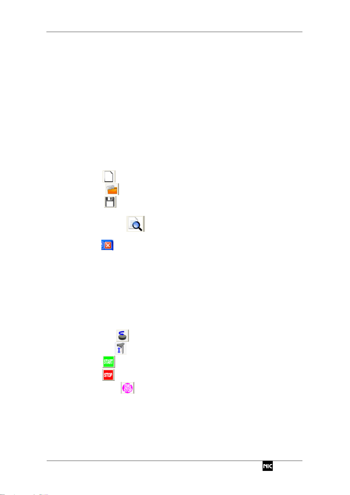
7.3.1. New ....................................................................................................... 47
7.3.2. Open ..................................................................................................... 48
7.3.3. Save ....................................................................................................... 48
7.3.4. Page Setup..................................................................................................... 49
7.3.5. Print Preview ...................................................................................... 50
7.3.6. Printing............................................................................................................ 50
7.3.7. Quit ......................................................................................................... 52
7.4. Edit menu commands............................................................................................ 52
7.4.1. Copy................................................................................................................ 52
7.4.2. Cut .................................................................................................................. 52
7.4.3. Paste............................................................................................................... 52
7.4.4. Remove........................................................................................................... 53
7.4.5. Insert............................................................................................................... 53
7.4.6. Move............................................................................................................... 53
7.4.7. Save as csv file............................................................................................... 53
7.4.8. Save as jpg file ............................................................................................... 53
7.4.9. Add Data......................................................................................................... 53
7.5. Run menu commands............................................................................................ 54
7.5.1. Turn Tray ............................................................................................... 54
7.5.2. Lift Move ................................................................................................. 54
7.5.3. Start ........................................................................................................ 55
7.5.4. Stop ........................................................................................................ 55
7.5.5. Emergency ............................................................................................ 55
7.5.6. Reset............................................................................................................... 55
7.5.7. Measurement Conditions................................................................................ 56
7.5.8. Self-check....................................................................................................... 61
7.5.9. Leak check...................................................................................................... 63
7.5.10. Start and Lamp-off.......................................................................................... 64
7.5.11. Maintenance................................................................................................... 65
7.6. Table menu commands.......................................................................................... 70

NIC-600-2202-17
RA-4500
7.6.1. Memo Setup.................................................................................................... 70
7.6.2. Table Conditions ................................................................................. 71
7.6.3. Statistics (S) ........................................................................................ 74
7.6.4. Registration of sample name (R).................................................................... 77
7.6.5. Table column initialization (I) .......................................................................... 78
7.7. System menu commands ...................................................................................... 79
7.7.1. Setup of IPAddress(RA4/RA4Win)................................................................ 79
7.7.2. Setup of IPAddress(RA4Win)........................................................................ 80
7.7.3. Setup............................................................................................................... 81
7.7.4. Color Scheme Setup....................................................................................... 83
7.7.5. Firmware Update............................................................................................ 84
7.8. Window menu commands...................................................................................... 86
7.8.1. Screen change (Control Screen) .......................................................... 86
7.8.2. Screen change (Analysis Screen) ........................................................ 86
7.8.3. Usual and Precision/Management Change.................................................... 86
7.8.4. Screen Arrangement Initialization................................................................... 87
7.8.5. Sequence Log and Error History Labeling ..................................................... 87
7.9. Help menu.............................................................................................................. 89
7.9.1. Version information......................................................................................... 89
8. SELF-PRECISION MANAGEMENT............................................................................. 90
9. TEMPERATURE CALIBRATION FUNCTION.............................................................. 94
10. MAINTENANCE .......................................................................................................... 98
10.1 Daily inspection...................................................................................................... 98
10.2 Yearly inspection and replacement parts................................................................ 100
10.3 Error and warning ................................................................................................ 101
10.4 Recovery from power failure................................................................................ 103
10.5 Corrective actions................................................................................................ 104
10.5.1 Abnormal blank value................................................................................... 104
10.5.2 Poor sensitivity.............................................................................................. 105
10.5.3 Leakage........................................................................................................ 105
10.6 Replacing the parts.............................................................................................. 106
10.6.1 Removing the turntable................................................................................. 106
10.6.2 Replacing the reaction tube.......................................................................... 107
10.6.3 Replacing the reagent pump tube.................................................................110
10.6.4 Replacing the reagent tube ...........................................................................111
10.6.5 Replacing the tubes inside the detector........................................................113
10.6.6 Replacing the cap and bubbler......................................................................114
10.6.7 Replacing the lamp........................................................................................116
10.7 Cleaning method...................................................................................................117
10.7.1 Cleaning the reagent tube.............................................................................117
10.7.2 Cleaning the cap, bubbler, light absorption cell, and dehumidifier tube........117
11. CALCULATION............................................................................................................118
11.1 Conversion of reagent amounts............................................................................118
11.2 How to determine a calibration curve.................................................................. 120
11.2.1 Linear equations........................................................................................... 120
11.2.2 Cubic equations............................................................................................ 120
11.3 Standard addition................................................................................................. 122

NIC-600-2202-17
RA-4500
12. SPECIFICATIONS ...................................................................................................... 123
12.1. Component specifications.................................................................................... 123
12.1.1. Detecting unit................................................................................................ 123
12.1.2. Sample pretreatment & reduction unit.......................................................... 123
12.1.3. Reagent dispensing unit............................................................................... 124
12.1.4. Data processing system............................................................................... 124
12.2. Installation specifications..................................................................................... 125
12.2.1. Installation environment................................................................................ 125
12.2.2. Power supply specifications ......................................................................... 125
13. CONTACT................................................................................................................... 126

NIC-600-2202-17
1. Introduction
RA-4500
1
1. Introduction
1.1. Safety precautions
1.1.1. Meaning of safety alert symbols
Warning
Indicates that incorrect handling could result in the death or severe injury
to the operator.
Caution
Indicates that incorrect handling could result in moderate or minor injury
to the operator, or damage to property.
1.1.2. Installation precautions
Warning
•Ensure to connect the protective grounding to prevent electric shock.
1.1.3. Handling precautions
Warning
•Shut Off the power supply before starting any maintenance. Otherwise, it could
result in electric shock.
•Keep your hands away from the auto sampler during measuring operation, or they
could be caught in a moving part, and thus leading to injury as well as damage to
the instrument.
•When using a reagent, be sure to wear protective equipment and properly ventilate
the work area. Reagents to be used in this instrument contain acutely toxic
substances and corrosive substances.
Caution
•Do not touch any sample tubes or the sample table during and shortly after the
heating operation, or you may suffer burns because of its high temperature. Wait
until they cool down to around the room temperature before proceeding with work.
•Be careful when touching or handling any glass parts because they could have
been damaged during work. Failure to observe this may cause injury.
•Be sure to use the instrument within the specifications, or it may break down.
2. Overview of the instrument
NIC-600-2202-17
RA-4500
2
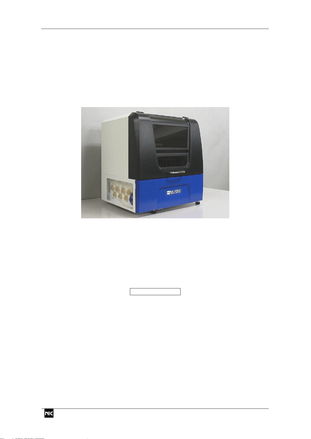
2. Overview of the instrument
The RA-4500 is a fully automatic mercury analyzer which carries out the wet
decomposition of samples such as drinking water and soil extracts, and then measures its
mercury content utilizing cold vapor atomic absorption spectroscopy.
It is capable of ultrahigh sensitivity measurement with a small quantity of samples. Since
the system determines an undecomposed sample, even less-experienced personnel can
perform the correct measurement.
2.1. Measurement principle
The instrument adds sulfuric acid, nitric acid, and potassium permanganate to the sample,
and after confirming that the potassium permanganate remains vermilion, adds potassium
peroxodisulfate. When this solution is heated, the mercury compounds in the solution are
oxidized and broken down into divalent mercury ion (Hg2+).
After leaving the solution standing to cool, the instrument adds a hydroxylammonium
chloride solution to remove excess potassium permanganate. When it adds a stannous
chloride (II) solution to this sample subjected to wet pretreatment, the divalent mercury ion
(Hg2+) is reduced to zero-valent metallic mercury and turns into mercury gas by bubbling.
Hg2++SnCl2→Hg0↑
After removing the acid mist and water vapor generated by bubbling with the electronic
cooling unit, the instrument measures the absorbance of mercury at 253.7 nm which is the
first absorption wavelength.
It measures the known mercury amount, creates a calibration curve, and then calculates the
mercury amount from the absorbance.

NIC-600-2202-17
2. Overview of the instrument
RA-4500
3
2.2. Part names and functions
2.2.1. Front
Dispensing cap
Optical system
Measuring cap
V3 valve
Color sensor
V1 valve
Reagent stand
Flow sensor
Rinse container
Door lock
Dehumidifier
Heating table
V2 valve
Sample tube
Drain tank
Dispensing arm
2. Overview of the instrument
NIC-600-2202-17
RA-4500
4
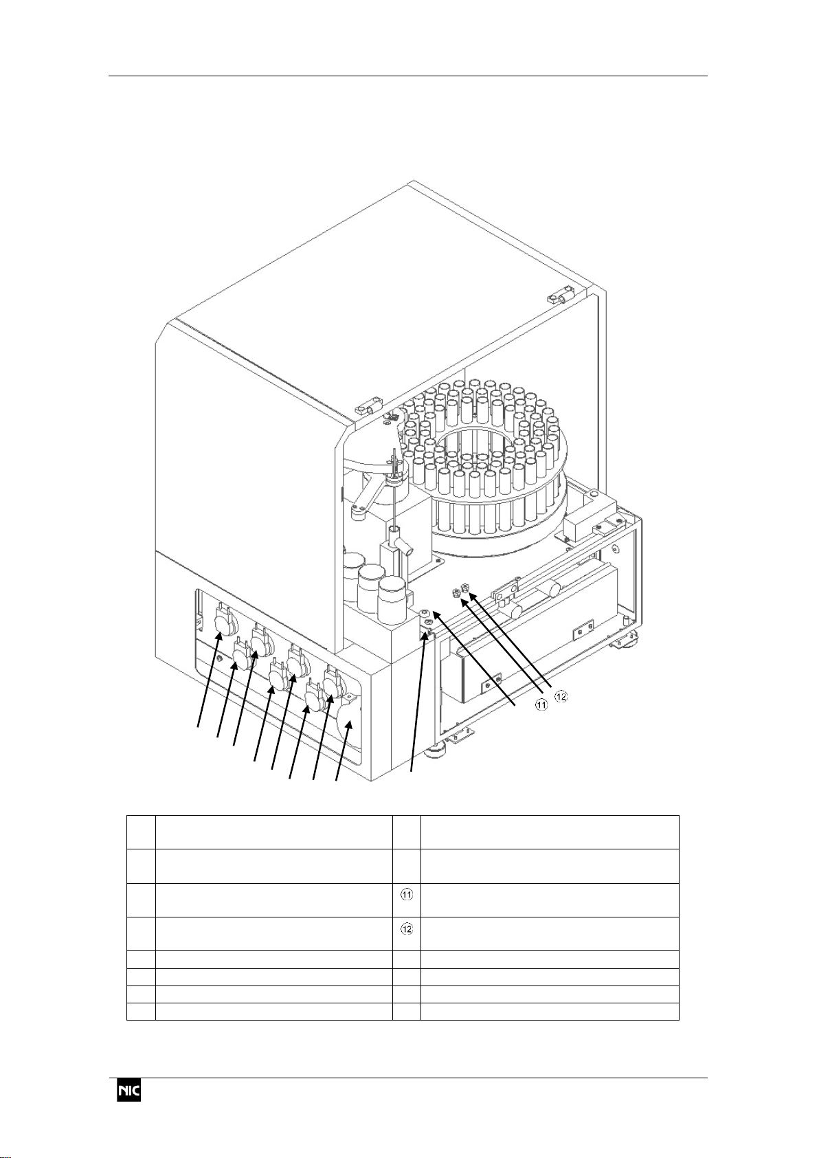
2.2.2. Left side
Air pump
Opening for drawing out the effluent
hose
Reagent pump P1
Grommet for (transparent) reaction
tube
Reagent pump P2
Connection port for (green) reaction
tube
Reagent pump P3
Connection port for (yellow) reaction
tube
Reagent pump P4
Reagent pump P5
Reagent pump P6
Rinse pump P7

NIC-600-2202-17
2. Overview of the instrument
RA-4500
5
2.2.3. Right side
Connectors to optional units.
Cooling fan
Main switch
Main power connector
Power connector for duct fan
LAN cable port
RS-232C port
Ventilation fan (with filter)
Duct fan

2. Overview of the instrument
NIC-600-2202-17
RA-4500
6
2.3. Measurement flow
The instrument drips a reagent for pretreatment using the reagent pumps P1 to P4 and
drips a reducing agent using the reagent pumps P5 and P6.
After the dripping reagents, it turns the rotor using the stirrer located under the turntable to
stir the sample.
Carrier gas is introduced into the purge line, measuring line, or blowing line by the
switching V1, V2 and V3. The bubbler is washed in the rinse bottle after measurement.
Cell
Yellow
Activated
carbon case
Mercury
lamp
Sample tube
Rinse bottle
Air pump
V1
V3
V
s
V2
V
R
H
2
SO
4
KMnO
4
HNO
3
P1
P2
P3
P4
K
2
S
2
O
8
HONH
3
Cl
SnCl
2
P5
P6
P7
DW
スターラー
Effluent bottle
Cap
Bubbler
Stirrer
Dehumidifier
section
Drain tank
Green

NIC-600-2202-17
2. Overview of the instrument
RA-4500
7
2.3.1. Purge line
Before starting measurement, the instrument replaces the gas in the absorption cell and
measuring line.
The valves V3 and V2 turn ON, and the carrier gas flows through the channel shown in
the figure below.
Bubbler
Mercury
lamp
Activated
carbon case
Air pump
Rinse bottle
V1
V3
V
s
V2
V
R
H
2
SO
4
KMnO
4
HNO
3
P1
P2
P3
P4
K
2
S
2
O
8
HONH
3
Cl
SnCl
2
P5
P6
P7
DW
Sample tube
Effluent bottle
Cap
Yellow
Cell
Dehumidifier
section
Drain tank
Green

2. Overview of the instrument
NIC-600-2202-17
RA-4500
8
2.3.2. Measuring line
After dripping stannous chloride (II) into the sample, the instrument carries out bubbling in
the sample tube to gasify mercury, and measures its absorbance in the cell.
The valves V1, V2 and V3 turn ON, and the carrier gas flows through the channel shown
in the figure below.
* Bubbling does not occur when there is a leak in the line.
Bubbler
Cap
Rinse bottle
Mercury
lamp
Air pump
Activated
carbon case
Sample tube
V1
V3
V
s
V2
V
R
H
2
SO
4
KMnO
4
HNO
3
P1
P2
P3
P4
K
2
S
2
O
8
HONH
3
Cl
SnCl
2
P5
P6
P7
DW
Effluent bottle
Yellow
Cell
Dehumidifier
section
Drain tank
Green

NIC-600-2202-17
2. Overview of the instrument
RA-4500
9
2.3.3. Blowing line
This line is a channel used to purge chlorine gas after bubbler cleaning in the rinse bottle
or after dripping a hydroxylammonium chloride solution. The instrument uses this channel to
drip the water accumulated in the dehumidifier tube, into the drain tank.
The air pump runs with all of the valves V1, V2 and V3 set to OFF, which allows the carrier
gas to flow through the channel shown in the figure below.
Mercury
lamp
Activated
carbon case
Sample tube
Bubbler
Cap
Dehumidifier
section
Rinse bottle
V1
V3
V
s
V2
V
R
H
2
SO
4
KMnO
4
HNO
3
P1
P2
P3
P4
K
2
S
2
O
8
HONH
3
Cl
SnCl
2
P5
P6
P7
DW
Effluent bottle
Yellow
Cell
Drain tank
Air pump
Green
2. Overview of the instrument
NIC-600-2202-17
RA-4500
10
2.4. Operation sequence
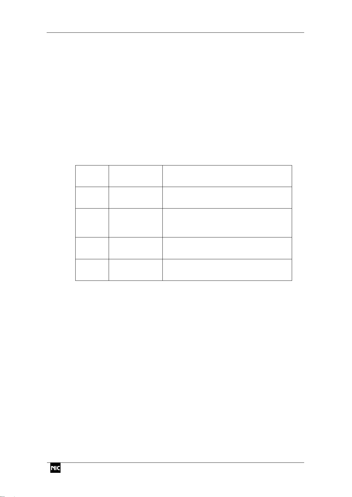
The following three patterns of operation sequence are available depending on the
Pretreatment setting in the Measurement Condition window.
Pretreatment Without : Neither standard samples nor unknown samples
are pretreated.
Pretreatment With : Both standard samples and unknown samples are
pretreated under the same conditions.
Pretreatment Sample Only : Standard samples are measured by the
“Pretreatment Without” option, and unknown
samples are measured by the “Pretreatment With”
option.
The following four measurement methods 1-5 were registered before shipping the product.
Method1
Pretreatment
Without
For samples that contain no interfering
ingredients (Prepared as per JIS-K0102
“Testing methods for industrial wastewater”)
Method2
Pretreatment
With
For river water and drinking water
(Prepared as per Ministry of Health, Labour
and Welfare notice No. 261)
Method3
Pretreatment
With
For environmental samples that involve
water contamination
(Prepared as per Appendix 2 of Notification
No. 59 of the Ministry of Environment)
Method4
Pretreatment
Sample Only
For industrial wastewater samples
(Prepared as per JIS-K0102 “Testing
methods for industrial wastewater”)
Method5
Pretreatment
Sample Only
For absorption solution of stack gas
(Prepared as per No. 94 of the Ministry of
Environment)
* The amount of reagents can be changed freely, as long as the total setup amount is lower
than 10 mL.
* Changing the reagent concentration could damage or block a tube.
* If pretreatment is carried out, addition of the sample is not allowed. When starting the
decomposition of an unknown sample after checking the calibration curve with “sample
only” option, do not put a check in the unknown sample in the SMP tab.

NIC-600-2202-17
2. Overview of the instrument
RA-4500
11
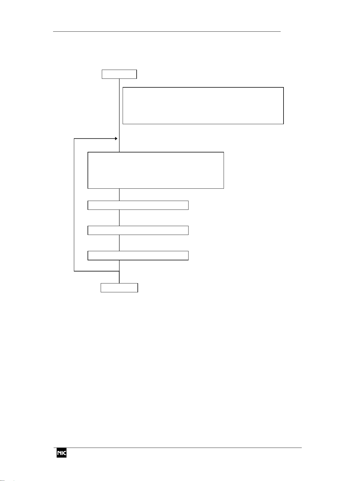
2.4.1. Without Pretreatment (Method 1)
* The same sequence is used in the Method 4 for measurement of standard samples,
except that no sample addition is allowed.
Repeat the cycle for all samples
Start
In the Method 1 (unpretreated samples), the sample may be
added during measurement.
* In this method, the system does not carry out the Sample
presence check.
* The door lock is also disabled.
End
Reagent dispensing
Sample presence check
Sulfuric acid (1+1) (Normally 0.9 mL)
10% stannous chloride solution
(Normally 0.5 mL)
Measurement (Normally 120 sec.)
Output of measurement results
Bubbler cleaning (Normally 7 sec.)

2. Overview of the instrument
NIC-600-2202-17
RA-4500
12
2.4.2. With Pretreatment (Method 3)
Start
End
Reagent dispensing (Carried out for all samples to be measured)
Nitric acid (1+3) (Normally 0.5 mL)
Sulfuric acid (1+1) (Normally 0.5 mL)
5% potassium permanganate solution (Normally 0.5 mL)
Letting it stand
Reagent dispensed period is memorized for each sample; and after a lapse of 15
minutes, color check starts.
* It is possible to make settings of starting color check after dispensing all reagents.
Color check (1)
If the solution is vermilion, a 3% potassium peroxodisulfate solution (normally 0.5
mL) will be dripped into it.
If the vermilion disappears, a potassium permanganate solution will be added in
the sample and then returned to "Letting it stand" step.
* If the amount of P1 reagent is set to more than 0.7mL and P1 reagent is to be
added to all 80 samples again, the amount of reagent will not be enough.
Heating (Normally 95°C for 2 hours)
Cooling (Normally for 60 min.) If the sample temperature exceeds 40°C after the
preset time, it will be cooled down to 40°C or less.
Reagent dispensing
1.0% hydroxylammonium chloride solution (Normally 2.5 mL)
Stirring, and chlorine gas purging
10% stannous chloride solution (Normally 0.4 mL)
Bubbler cleaning (Normally 7 sec.)
Measurement (Normally 120 sec.)
Presence check for all samples
* If no sample is detected for a checked item, the confirmation message appears.
Color check (2)
Check of residual permanganate ion (Normally disabled)
Output of measurement results
NIC-600-2202-17
2. Overview of the instrument
RA-4500
13
2.4.3. With Pretreatment (only sample) (Method 5)
Repeat the cycle for all samples
Start
* The sample presence check can be used in method2-4 as
an auxiliary function, but it cannot be used in method5
because these samples have the color of potassium
permanganate solution.
End
Reagent dispensing
Sample presence check
Sulfuric acid (1+1) (Normally 0.6 mL)
10% stannous chloride solution
(Normally 0.3 mL)
Measurement (Normally 120 sec.)
Output of measurement results
Bubbler cleaning (Normally 7 sec.)

2. Overview of the instrument
NIC-600-2202-17
RA-4500
14
Start
End
Letting it stand
Reagent dispensed period is memorized for each sample; and after a lapse of 15
minutes, color check starts.
* It is possible to make settings of starting color check after dispensing all reagents.
Color check (1)
If the solution is vermilion, a 3% potassium peroxodisulfate solution (normally 0.5
mL) will be dripped into it.
If the vermilion disappears, a potassium permanganate solution will be added in
the sample and then returned to "Letting it stand" step.
* If the amount of P1 reagent is set to more than 0.7mL and P1 reagent is to be
added to all 80 samples again, the amount of reagent will not be enough.
Heating (Normally 95°C for 1 hours)
Cooling (Normally for 60 min.) If the sample temperature exceeds 40°C after the
preset time, it will be cooled down to 40°C or less.
Reagent dispensing
1.5% hydroxylammonium chloride solution (Normally 2.7 mL)
* It is the concentration the when absorption solution is diluted to 300mL.
If dilution rate is different, only change the concentration and keep the
reagentamount to 2.7mL.
Stirring, and chlorine gas purging
10% stannous chloride solution (Normally 0.5 mL)
Bubbler cleaning (Normally 7 sec.)
Measurement (Normally 120 sec.)
Color check (2)
Check of residual permanganate ion (Normally disabled)
Output of measurement results
Reagent dispensing (This operation is not carried out in the default setting)
* If the sample is at neutral pH due to the dilution of the absorption solution etc.,it
is better to add sulfuric acid (1+1).

NIC-600-2202-17
3. Installation and connections
RA-4500
15
3. Installation and connections
3.1. Installation of the instrument
(1) Place the RA-4500 at the installation position.
(2) Connect the duct hose to the exhaust fan.
(3) Connect the power cable and LAN cable (straight cable) to each connector on
the back.
(4) Set the instrument in place, and adjust the adjuster bolts to prevent wobbles.
(5) Place the effluent tank on the left side of the instrument, and tighten the cap.
* Ensure that the tube does not get in contact
with the liquid inside.
(6) Connect the LAN cable to the PC.
(7) Connect the power cable to the power outlet.
* Be sure to connect it to a grounded outlet.
Table of contents
Other Nippon Measuring Instrument manuals

Nippon
Nippon MA-3 Solo User manual

Nippon
Nippon EMP-3 User manual

Nippon
Nippon MA-3000 User manual

Nippon
Nippon Mercury/PE-1 User manual

Nippon
Nippon AQUA User manual

Nippon
Nippon Hi-Lutor User manual

Nippon
Nippon MA-3 Solo User manual

Nippon
Nippon MA-3000 User manual

Nippon
Nippon EMP-3 User manual

Nippon
Nippon WA-5A User manual


