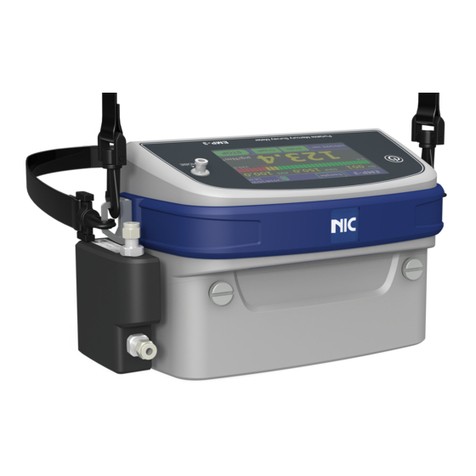
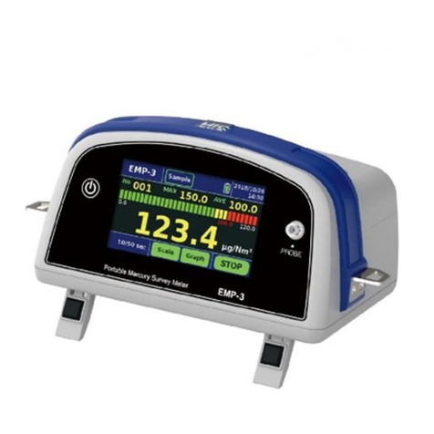
Nippon EMP-3 User manual

1/42
No.
EMP-3 Service Manual
Document
Number NIC-704-2031 Date of
Issue Feb. 26, 20
Control
Department Service Page 1/42
EMP-3
Service Manual
Nippon Instruments Corporation
Technical Service Group
Date Prepared Checked Approved
First
edition
Feb. 26,
2020
Yasumatsu Daito
Daito

2/42
No.
EMP-3 Service Manual
Document
Number NIC-704-2031 Date of
Issue Feb. 26,
20
Control
Department Service Page 2/ 42
Revision history
Edition Date of
change/revision
Reason for change/revision Prepared Approved
01 February 26,
2020 Issue of first edition Yasumatsu Daito

Contents
3/42
No.
Portable Mercury Survey Meter
Mercury/EMP-3 - Service Manual
Contents
1.INTRODUCTION ................................................................................................................ 5
2.LIST OF FREQUENTLY INQUIRED ISSUES.................................................................... 5
3.COMPONENTS AND PARTS RECOMMENDED FOR REPLACEMENT ........................ 6
4.OVERHAUL........................................................................................................................ 7
5.REPLACING COMPONENTS AND PARTS...................................................................... 9
5.1. Replacing the lamp.................................................................................................. 9
5.2. Replacing the air pump...........................................................................................11
5.3. Replacing the tubes/fittings.................................................................................... 13
5.4. Replacing the ZERO filter...................................................................................... 17
5.5. Replacing the valve................................................................................................ 18
5.6. Replacing the main board...................................................................................... 20
5.7. Replacing the LCD................................................................................................. 23
5.8. Replacing the LCD sheet....................................................................................... 24
5.9. Replacing the plastic case..................................................................................... 26
5.10. Removing the back cover and optical unit............................................................. 28
6.WASHING THE CELL...................................................................................................... 30
7.SIMPLIFIED CALIBRATION............................................................................................ 32
7.1. Preparing the standard gas ................................................................................... 32
7.2. Procedure for calculating the concentration of the standard gas.......................... 33
7.3. Amount of mercury in the standard gas................................................................. 34
7.4. Calibration.............................................................................................................. 35
8.MAKING CHECKS AND ADJUSTMENTS...................................................................... 37
8.1. Adjusting the optical unit........................................................................................ 37
8.2. Conducting the leak check and adjusting the flow rate......................................... 38
8.3. I/O check................................................................................................................ 39
8.4. Resetting the amount of adsorbed mercury.......................................................... 40
9.APPENDIX........................................................................................................................ 41

Contents
4/42
No.
9.1. Removal drawing of the back cover ...................................................................... 41
9.2. Removal drawing of the optical unit....................................................................... 41
9.3. Drawing of the optical unit ..................................................................................... 41
9.4. Drawing of the cell ................................................................................................. 42

1. Introduction
5/42
No.
1. Introduction
This document describes the procedures and methods for overhauling the EMP-3,
replacing its components, and making readjustments. The work involves the disassembly,
reassembly, and reinspection of the EMP-3. Use this Service Manual in combination with
the Instruction Manual.
2. List of frequently inquired issues
Shown below is the list of major inquiries from customers, addressed to the service
department and our dealers.
Referring to this list, provide the service based on the inquiry.
Inquiry Action Refer to
Overhaul Request for overhaul Overhaul 4.
The error message
does not disappear.
AD FULL Contact us. -
LAMP BROKEN Replace the lamp. 5.1.
CELL DARK Wash the parts.
Replace the tubes.
5.3.
The warning message
does not disappear.
EXCHANGE LAMP Replace the lamp. 5.1.
EXCHANGE PUMP Replace the pump. 5.2.
EXCHANGE ZERO FILTER Replace the ZERO
filter.
5.4.
Others Request for recalibration Conduct recalibration. 7.
LCD failure Replace the LCD. 5.7.
Valve failure Replace the valve. 5.5.
Request for replacing the case Replace the case. 5.9.
The clock cannot be set. Replace the battery. -

3. Components and parts recommended for replacement
6/42
No.
3. Components and parts recommended for replacement
Shown below is a list of components and parts recommended for periodic replacement in
order to use the EMP-3 stably. Note that their actual service lives depend on the condition
of use. Instruct your customers to schedule yearly maintenance.
Item Recommended replacement interval and guideline
Battery 1 year or upon 300 charges
(The capacity drops to about 60% after 300 charges.)
Mercury lamp 1 year or 2000 hours
Air pump 2 years or 2000 hours
Tubes and fittings 1 year or after high-concentration mercury measurement
Valves After high-concentration mercury measurement
ZERO filter 6 months or at 80 µg of adsorbed mercury
Probe filter 1 month or 500 hours
Probe tube 3 months or 1000 hours
Probe connector 6 months
* The recommended replacement intervals are not the guaranteed service lives.
* When you remove tubes to replace a pump or valve or for other reasons, we
recommend replacing the tubes and fittings at the same time. Once the tubes are
connected, they stretch at the connection, which may lead to leakage when the
tubes are connected again.

4. Overhaul
7/42
No.
4. Overhaul
This chapter describes the methods and procedures for conducting the overhaul of the EMP-
3 at the customers’ request.
(1) Get the items needed
Confirm that you have all the parts of the maintenance kit.
No. Item Part No. Qty. Remarks
EMP-3 - 1 -
Lamp To be confirmed 1 For replacement
Air pump W169-6200 1 For replacement
Maintenance kit S-W014-0200 1 For replacement (see 5.3. for details)
ZERO filter W121-0500 1 For replacement

4. Overhaul
8/42
No.
(2) Work to be conducted
The overhaul consists of the following three steps.
Replacement of components and parts (lamp, air pump, tubes, and ZERO filter)
Washing of components and parts (optical unit)
Recalibration of EMP-3
(3) Procedure
Remove the back cover and the optical unit. (Refer to 5.10. Removing the back cover
and optical unit.)
Replace the following parts.
Wash the cell parts. (Refer to 6. Washing the cell.)
* This step is not mandatory. If you have omitted this step, check the voltages of the
optical unit, and confirm that the Sig voltage and the Ref voltage are the same.
Attach the back cover and the optical unit. (Refer to 5.10. Removing the back cover and
optical unit.)
After the EMP-3 is assembled, replace the ZERO filter.
Reset the amount of adsorbed mercury. (Refer to 8.4. Resetting the amount of adsorbed
mercury.)
Conduct the leak check and adjust the flow rate. (Refer to 8.2. Conducting the leak
check and adjusting the flow rate.)
Conduct the recalibration. (7. Simplified calibration)
Parts to be replaced Replacing parts Refer to
Lamp 5.1. Replacing the lamp
Air pump 5.2. Replacing the air pump
Tubes and fittings 5.3. Replacing the tubes/fittings
Parts to be replaced Replacing parts Refer to
ZERO filter 5.4. Replacing the ZERO filter

5. Replacing components and parts
9/42
No.
5. Replacing components and parts
5.1. Replacing the lamp
(1) Get the items needed
(2) Replace the parts
Remove the back cover and the optical unit. (Refer to 5.10. Removing the back cover
and optical unit.)
Remove the two nuts, and detach the mercury lamp.
No. Item Part No. Qty. Remarks
EMP-3 ―1
Lamp To be confirmed 1 For replacement
Two nuts

5. Replacing components and parts
10/42
No.
Hold the base of the lamp, and pull off the lamp cover.
Replace the lamp, and attach the lamp cover.
*Attach the lamp cover so that the wire entry hole faces the right and that the red marking
of the lamp is located on the upper side.
Replace other parts, if any. If there are no other parts to be replaced,assemble the EMP-
3 through the following procedure.
Attach the lamp to the optical unit. (Refer to Step .)
Attach the optical unit and the back cover. (Refer to 5.10. Removing the back cover and
optical unit.)
Start up the EMP-3, and confirm that the lamp voltage is indicated on the Maintenance
screen.
Adjust the optical system and conduct the recalibration. (Refer to 8.1. Adjusting the
optical unit and 7. Simplified calibration.)
Wire entry hole
Red marking
Wire entry hole
Red marking

5. Replacing components and parts
11/42
No.
5.2. Replacing the air pump
(1) Get the items needed
(2) Replace the parts
Remove the back cover and the optical unit. (Refer to 5.10. Removing the back cover
and optical unit.)
Cut the two cable ties at the optical unit, pull out the tubes connected to the pump, and
detach the air pump.
No. Item Part No. Qty. Remarks
EMP-3 - 1
Air pump W169-6200 1 For replacement
Cable ties (general-purpose) 150mm 2 For replacement
Tubes
Two cable ties

5. Replacing components and parts
12/42
No.
Attach a new air pump, align it with the right end of the rubber cover of the optical unit,
and fix it in place.
Pass the two cable ties between the case and the mounting bracket of optical unit, and
fix the air pump in place.
Connect the inlet and outlet tubes to the air pump.
Pass the fitting from the valve, between the tubes.
Replace other parts, if any. If there are no parts to be replaced, assemble the EMP-3
through the following procedure.
Attach the optical unit and the back cover. (Refer to 5.10. Removing the back cover and
optical unit.)
Conduct the leak check and adjust the flow rate. (Refer to 8.2. Conducting the leak
check and adjusting the flow rate.)
Top view of optical unit
Rubber cover
Mounting bracket
Optical unit case
Pass the fitting between the tubes.
Pass cable ties.
Side view of optical unit

5. Replacing components and parts
13/42
No.
5.3. Replacing the tubes/fittings
Replace the tubes and the fittings through which sample gas passes.The photos below show
the parts used in each section.
(1) Get the items needed
No. Item Section Part No. Qty. Remarks
EMP-3 - - 1
Maintenance kit list 1/2 - S-W014-0200 1 For replacement
Female luer fitting partition connector (VRBF108) Inlet 1 For replacement
Tube (SE-200 1/16x1/8x1/32) 170mm 1 For replacement
Mini fitting partition connector (VFB226) Outlet 1 For replacement
Tygon tube (LMT-55 3/32x5/32x1/32) 200mm 1 For replacement
Mini connector reducing L type (MCL1522) Valve 2 For replacement
Mini connector reducing T type (MCT151522V) 1 For replacement
ARAMEC FU tube (transparent) (1516-01) 12mm 3 For replacement
Inlet/Outlet
Valve
Air pump
Temperature sensor
Downstream of valve to ZERO filter
Probe

5. Replacing components and parts
14/42
No.
*Tubes of maintenance kit are not cut, please cut them to the specified length by yourself.
(2) Replace the parts (* Insert the tubes into the joints as far as they will go.)
Remove the back cover and the optical unit. (Refer to 5.10. Removing the back cover
and optical unit.)
Replace the tubes and the fittings of the inlet and outlet sections.
• Loosen the nuts at the inlet and
outlet, and detach the tubes and
the fittings.
• Attach new
tubes and the fittings,
and fix the fittings in place with the
nuts.
• Insert the tubes into the fittings.
No. Item Section Part No. Qty. Remarks
Maintenance kit list 2/2 - S-W014-0200 1 For replacement
Mini fitting (VGI-238) Air pump 1 For replacement
Mini fitting (VFI346) 1 For replacement
Tygon tube (LMT-55 1/8x3/16x1/32) 20mm 1 For replacement
Tygon tube (LMT-55 1/8x3/16x1/32) 30mm 1 For replacement
Tygon tube (LMT-55 3/16x5/16x1/16) 130mm 1 For replacement
Mini fitting (VFI146)
Temperature
sensor
1 For replacement
Tygon tube (LMT-55 1/16x1/8x1/32) 38mm 1 For replacement
Tygon tube (LMT-55 1/16x1/8x1/32) 50mm 1 For replacement
Tygon tube (LMT-55 1/16x3/16x1/16) 25mm 1 For replacement
Filter joint
Downstream of
valve to ZERO
filter
2 For replacement
Tube (SE-200 1/16x1/8x1/32) 95mm 1 For replacement
Tube (SE-200 1/16x1/8x1/32) 105mm 1 For replacement
Tube (SE-200 1/16x1/8x1/32) 110mm 1 For replacement
Luer fitting (VRM206) Probe 1 For replacement
Filter unit (25JP050AN) 1 For replacement
ARAMEC FU tube (transparent) (1516-01) 1m 1 For replacement

5. Replacing components and parts
15/42
No.
Replace the tubes and the fittings at the valve section.
• Pull the tubes and the fittings off the valve.
• Insert the tubes into the new fittings, and
attach them to the valve.
Replace the tubes and the fittings at the air pump section.
• Remove the tubes and the fittings from the air
pump.
•
Insert the tubes into the new fittings, and
attach them to the air pump.
Replace the tubes and the fittings at the temperature sensor section.
• Loosen the screws for the
optical unit cover, open the
cover, and remove the tubes
from the cell.
• Remove the tubes and the fitting
from the temperature sensor.
• Attach the new tubes to the cell,
and close the optical unit case.
• Attach the tubes and the fitting
to the temperature sensor.

5. Replacing components and parts
16/42
No.
Replace the tubes and the fittings at the section between the downstream of the valve
and the ZERO filter.
• Remove the tubes and the
filter joints.
• Insert the new tubes into the
fittings , and attach the
opposite end to the filter
joints and the cell.
* Attach the tubes so that the tube runs on the optical unit case side and the tubes
run on the outer side.
Replace the probe.
• Remove the luer fitting, and detach the handle of the probe.
• Insert the handle of the probe into the new tube, and attach the luer fitting and the filter
unit.
Replace other parts, if any. If there are no parts to be replaced, assemble the EMP-3
through the following procedure.
Attach the optical unit and the back cover. (Refer to 5.10. Removing the back cover and
optical unit.)
Conduct the leak check. (Refer to 8.2. Conducting the leak check and adjusting the flow
rate.)

5. Replacing components and parts
17/42
No.
5.4. Replacing the ZERO filter
(1) Get the items needed
(2) Replace the parts
Open the filter cover, and replace the ZERO filter.
* With the ZERO filter’s label pointing toward the upper side of the EMP-3, insert the
ZERO filter as far as it will go.
Insufficient insertion may result in leakage and incorrect measurement.
After the replacement of the ZERO filter, reset the amount of adsorbed mercury on the
Setting screen.
(Refer to 8.4. Resetting the amount of adsorbed mercury.)
No. Item Part No. Qty. Remarks
EMP-3 - 1
ZERO filter W121-0500 1 For replacement

5. Replacing components and parts
18/42
No.
5.5. Replacing the valve
(1) Get the items needed
(2) Replace the parts
Remove the back cover and the optical unit. (Refer to 5.10. Removing the back cover
and optical unit.)
Pull out the three tubes, cut the two cable ties, and detach the valve.
No. Item Part No. Qty. Remarks
EMP-3 - 1
Valve W169-6300 1 For replacement
Cable ties (general-purpose) 150 mm 2 For replacement
Tubes
Two cable ties

5. Replacing components and parts
19/42
No.
Replace the valve, align it with the left end of the rubber cover of the optical unit, and fix
it in place.
Pass the two cable ties between the case and mounting bracket of the optical unit, and
fix the air pump in place.
Connect the three tubes to the valve.
Replace other parts, if any. If there are no parts to be replaced, assemble the EMP-3
through the following procedure.
Attach the optical unit and the back cover. (Refer to 5.10. Removing the back cover and
optical unit.)
Start up the EMP-3, and confirm that the valve operates normally. (Refer to 8.3. I/O
check.)
Conduct the leak check. (Refer to 8.2. Conducting the leak check and adjusting the flow
rate.)
Top view of optical unit
Rubber cover
Mounting bracket
Optical unit case
Pass cable ties.
Side view of optical unit
Side view of optical unit
Top view of optical unit

5. Replacing components and parts
20/42
No.
5.6. Replacing the main board
(1) Get the items needed
(2) Replace the parts
Remove the back cover and the optical unit. (Refer to 5.10. Removing the back cover
and optical unit.)
Disconnect the Sig, Power, LCD, GPS, and Ref connectors from the main board.
Disconnect the connector from the USB board.
No. Item Part No. Qty. Remarks
EMP-3 - 1
Main board To be confirmed 1 For replacement
Ref
GPS
USB board
LCD
Power
Sig
Other manuals for EMP-3
1
Table of contents
Other Nippon Measuring Instrument manuals
Nippon
Nippon Mercury/PE-1 User manual
Nippon
Nippon EMP-3 User manual
Nippon
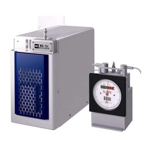
Nippon WA-5A User manual
Nippon
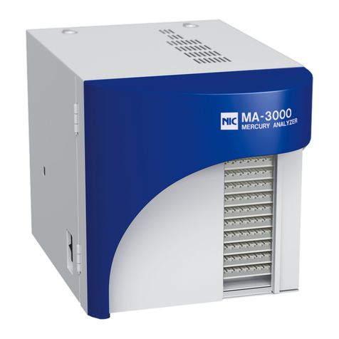
Nippon MA-3000 User manual
Nippon
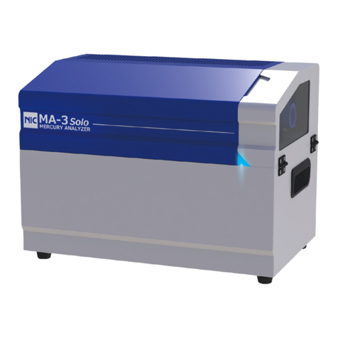
Nippon AQUA User manual
Nippon
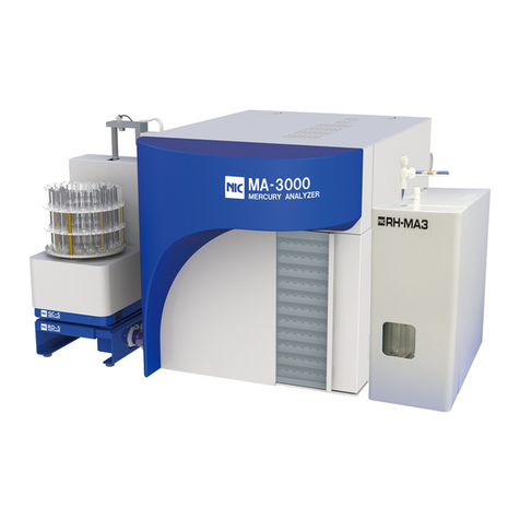
Nippon MA-3000 RD-5+SC-5 User manual
Nippon
Nippon MA-3 Solo User manual
Nippon
Nippon RA-4500 User manual

Nippon
Nippon MA-3 Solo User manual

Nippon
Nippon MA-3000 User manual
Popular Measuring Instrument manuals by other brands
Motorola
Motorola R2010D Operator's manual
DH Instruments
DH Instruments MOLBLOC-S instruction sheet
Granite River Labs
Granite River Labs GRL-USB-PD-A1 user manual
palintest
palintest Lumiso Pooltest Expert quick start guide

Milwaukee
Milwaukee EC40 instruction manual
MADDALENA
MADDALENA microCLIMA ULTRA Installation and operating instructions
