manuals.online logo
Brands
  1. Home
  2. •
  3. Brands
  4. •
  5. NiteRider
  6. •
  7. Bicycle Accessories
  8. •
  9. NiteRider PRO 3600 DIY REMOTE User manual

NiteRider PRO 3600 DIY REMOTE User manual

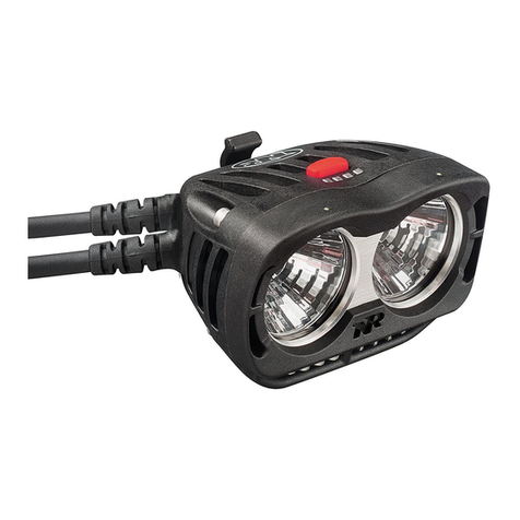
PRO 3600 DIY REMOTE
USER GUIDE
Now with Remote Switch
USE THE LIGHT THAT PROS USE
NiteRider™ provides mountain bike riders the most durable, reliable
and best performing lights in the market. It’s not a statement we make
lightly, as the backbone of our success has been built on providing
lights of exceptional quality to this very demanding market sector.
Through 22 years of actively supporting professional riders at 12 and
24 hour endurance events we have learned what it takes to become
the stand alone leader in mountain bike lighting.
PARTS LIST AND IDENTIFICATION
Please verify the contents of your Pro 3600 DIY system:
A. Dual Beam Headlamp
B. Li-Ion Battery
C. Universal Handlebar Mount (UHM)
D. Docking Station
E. AC Adapter
F. 36” Extension Cord
G. USB Cable
H. Battery Tray
I. Remote Switch
Handlebars not included
A.
I.
B.
C.
D.
E.
F.
MOUNTING THE HEADLAMP
The Pro 3600 DIY headlamp can be mounted to the handlebar.
Universal Handlebar Mount
The Universal Handlebar Mount (UHM) is designed to t on virtually
any handlebar. Included with the mount is a 2.5 mm Allen wrench
for adjusting the mount.
1. Turn the knob counter-clockwise, allowing the hinge to swing open.
2. Place the UHM on the handlebar on the left side of the stem,
orienting the rectangular notch in the slider clip to the rear.
3. Swing the hinge down to make contact with the handlebar.
4. Swing the bolt up, seating the knob into its recess.
5. Turn the knob clockwise to tighten and secure the mount
to the handlebar.
The UHM can be adjusted to accommodate any handlebar angle.
By loosening the 2.5 x 30 mm Allen screw, you can move the
swing arm back and forth to straighten the headlamp.
Tighten the 2.5 x 30 mm screw after the adjustment. To pivot the
headlamp, loosen the 2.5 x 12 mm screw located under the slider
clip and swing arm and rotate the headlamp to the desired position.
Make this adjustment before tightening the 2.5 x 30 mm screw.
Inserting the Headlamp into the Handlebar
Insert the headlamp into the handlebar or helmet mount slider clip
from the rear moving forward. Gently rocking the lamp as you slide it
may help. Do not push the release lever when inserting the headlamp
into the slider clip; let the lamp snap into place by itself.
To remove the headlamp, push the release lever forward and slide the
lamp backward.
Note: After mounting the headlamp, adjust it so the beam illuminates the road without
distracting oncoming riders.
CLICK!
MOUNTING THE BATTERY SYSTEM
The “battery system” consists of a tray, which mounts to the bike
frame, and a Li-Ion battery that releases quickly from the tray for
charging. The battery system can also be placed in a jersey pocket,
hydration pack or fanny pack when helmet mounting the headlamp
Warning: For safety reasons, a cyclist should never be tethered
to the bike. If the headlamp is mounted to the helmet, do not
mount the battery system to the frame. Conversely, if the
headlamp is mounted to the handlebar, do not place the
battery system in a pocket or pack.
Frame Mount
1. Thread the velcro straps through the 2 slots on the bottom
of the battery tray.
2. Attach the concave surface of the tray to a safe, convenient
location on the frame (typically under the top or down tube),
placing the velcro strap over the tube, under any shift or
brake cables. The cable from the tray should extend toward
the stem.
3. Secure the headlamp and battery tray cables to the frame using
the thin velcro strapettes. Make sure the cables do not interfere
with any moving parts.
4. Aligning the arrow on the bottom of the battery with the red
arrow inside the tray, slide the battery into the tray until you
hear a noticeable click.
Note: If a click is not heard when sliding the battery into the
tray, proper connection did not occur. Remove battery from tray
and repeat the process.
OPERATION
1. Connect the headlamp cable to the battery.
2. Press and release the headlamp power button to turn the light on.
Cycle through the four brightness levels by pressing and releasing
the power button.
3. To access the daylight safety ash mode, press and hold the
power button until the headlamp starts to ash.
OPERATION (cont.)
4. With the headlamp in ash mode, press and release the power
button to access beacon, SOS or walk modes. From walk mode
you can return to normal mode by pressing and releasing the
power button.
5. To turn the headlamp o from normal, ash or walk modes,
press and hold the power button until the headlamp shuts o.
6. Always disconnect the battery from the headlamp when
transporting the light system. This prevents accidentally turning
on the headlamp, which may cause overheating and potential
damage from high heat or even a risk of re.
Fuel Gauge
The 8-step, LED Fuel Gauge is located on top of the headlamp in
front of the power button. When all four LED’s are lit solid green,
the battery is fully charged. As the battery discharges ⅛ increments
of capacity, the LED’s from right to left, sequentially go from
solid green to blinking green, to out. With only the nal ⅛ capacity
remaining one LED blinks red. At this time, the headlamp should
be turned o and the battery recharged.
LED Indicators
The four LED indicators on top of the headlamp, in front of the
power button, have multiple uses - as fuel gauge steps and as
identiers when in the program select mode.
Program Select Mode
There are a total of 5 Programs to select from. The Pro 3600 DIY
headlamp has factory settings which are locked and cannot be
modied. In addition, the headlamp has memory to store four
(4) additional operating Programs which you create, modify and
download to the Pro 3600 DIY headlamp using the Docking Station.
Velcro Straps
Battery Tray
(Top View)
Battery Tray
(Bottom View)
Battery
(Bottom View)
G.
H.
RIDING AT NIGHT
While a Pro 3600 DIY lighting system will improve your view, control
and enjoyment of night riding, please remember that cycling at night
is an inherently dangerous activity. In addition to using your lighting
system properly and riding with extreme caution, NiteRider™ urges
you to:
• Never ride alone
• Always let someone know where you are going
• Wear a helmet and reective clothing
• Carry an auxiliary light and emergency supplies
• Make sure the headlamp, mounting bracket
and battery are securely fastened
• Always disconnect the battery from the headlamp
when transporting the light system
PROTECTING YOUR INVESTMENT
Properly charge your battery to maximize its lifespan (see the
“Battery Charging and Care” section for detailed information).
The Pro 3600 DIY will perform in wet weather conditions, but
submerging it in water will damage the system.
SUPPORT
If you experience diculties during product installation or operation,
NiteRider™ provides free telephone support on weekdays from
8:00 am to 4:30 pm (Pacic Time) at 800.466.8366, Ext 4.
You may also e-mail us at support@niterider.com.
WARRANTY
NiteRider™ stands behind its products with the following warranties:
• Lifetime warranty on all mechanical components
• 2 Years on electrical components
• 1 Year on rechargeable batteries
To obtain warranty service, it is preferable to have your original
sales receipt. Contact the NiteRider™ Customer Service
Department at 800.466.8366, Ext. 4 to obtain a Return Merchandise
Authorization (RMA) number. The RMA number
must be prominently displayed on the outside of your package.
The product must be properly packaged to prevent damage
in transit.
For complete warranty information, please visit our website at
www.NiteRider.com.
NiteRider™ Technical Lighting Systems, Inc.
8295 Aero Place, Suite 200
San Diego, CA 92123
www.NiteRider.com
Using the D.I.Y. Software
1. From the “O” position, press and hold the power button for 6
seconds to enter the Program Select Mode. The number of lit LED’s
will identify the Program currently being used.
- One LED lit red indicates the factory setting Program.
- One LED lit green indicates Program-1.
- The second LED from the left lit green indicates Program-2.
- The third LED from the left lit green indicates Program-3.
- All four LED’s lit green indicates Program-4.
2. Cycle through the ve (5) Programs by pressing and releasing
the power button.
3. To select a Program, press and hold the power button until all
lit LED’s begin to blink rapidly 5 times. Once a Program has been
selected, the light will operate under that.
Program specications. Before shipping, NiteRider has initialized
the memory for the 4 additional operating Programs
with factory settings.
Power Button Uses
The power button, located on the top of the headlamp, is used to
turn the light on, change light and ash levels, turn the light o and
access the Program Select mode.
• Light On
- Press and release the power button to turn the light on.
- Cycle through the brightness levels by pressing and releasing
the power button.
• Flash
- To access ash mode press and hold the power button for
greater than 3 seconds.
- Cycle through the ash patterns by pressing and releasing
the power button.
• Light Off
- To turn the light o while in either normal light or ash mode,
press and hold the power button for greater than 1 and less
than 3 seconds.
• Program Mode
- From the “O” position, press and hold the power button for
6 seconds to enter the ProgramSelect Mode.
FACTORY SETTINGS
Factory settings are locked and cannot be changed. The Pro 3600
DIY factory settings include 3 light levels and the one ash pattern.
See table below.
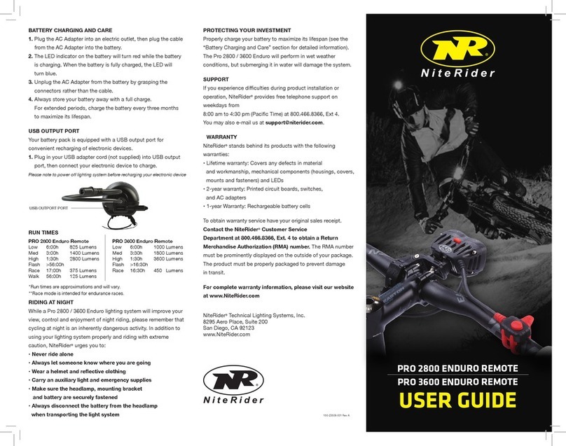
RUN TIMES* - FACTORY SETTINGS
Low 6:00h 1000 Lumens
Med 3:30h 1800 Lumens
High 1:30h 3600 Lumens
Flash >16:30h
Race** 16:30h 450 Lumens
*Run times are approximations and will vary.
**Race mode is intended for endurance races.
THERMAL STEP DOWN
If the Pro 3600 DIY headlamp is used in a static air environment,
such as bench testing, heat retention, due to inadequate airow,
may cause the light output to “step down” to a lower level to avoid
damage. In rare cases of extreme heat retention the light will power
o to protect the LED’s from overheating. Use a fan if bench testing
the light in a static air environment.
DOCKING STATION
The Docking Station has two uses.
1. To recharge the Pro Series Li-Ion battery.
2. To download Programs from the D.I.Y Software to the headlamp
BATTERY CHARGING AND CARE
Battery Recharging
A Pro 3600 DIY (8-cell, 7.4v, 11.6Ah, Li-Ion) will fully charge
in 5:00 hours.
1. Plug the AC Adapter into the Docking Station and then into
the wall socket. The “Power” indicator on the docking station will
illuminate solid red.
2. Place the battery into the Docking Station. The “Battery”
indicator will illuminate solid blue indicating contact and that
the battery is ready to charge. A blinking yellow indicator
signies the battery is out of the permissible temperature range
for charging.
3. Status of the 5-step charging process is displayed on the front
panel of the Docking Station.
4. When the battery is fully charged the “Charged” indicator will
illuminate solid green and charging will shut o automatically.
5. Leaving the battery in the Docking Station indenitely will not
harm the battery. Every 24-hours the Docking Station will test
the battery level and apply a charge if required.
Warning: If the “Batt Error” indicator illuminates solid red,
contact NiteRider Customer Service for assistance.
D.I.Y. SOFTWARE
The latest version of the D.I.Y Software is available to download at
www.niteriderservices.com
The software runs under Windows 2000 and above. For detailed
information on the software please refer to the “D.I.Y. Pro LED Series
Software Guide”.
DOWNLOAD PROGRAMS FROM THE D.I.Y. SOFTWARE
To download Programs from the D.I.Y. Software, the Docking
Station must be powered by a wall outlet, the Docking Station must
be connected to the host computer and the headlamp must be
connected to the Docking Station.
1. Plug the AC Adapter into the Docking Station and then into
the wall socket. The “Power” indicator on the docking station
will illuminate solid red.
2. Plug one end of the USB Cable into the Docking Station and
the other end into the USB port of a computer. The “USB/PC”
indicator will illuminate solid yellow.
3. Connect the Pro 3600 DIY headlamp to the Docking Station.
The “Headlamp” indicator will illuminate solid yellow.
4. Click the “Update” button on the D.I.Y. Software control panel
to initiate transmission of Programs to the headlamp. Refer to
the “D.I.Y. Pro LED Series Software Guide” for detailed
information on the software features and how they function.
5. Both the “USB/PC” and “Headlamp” indicators will blink
indicating Programs are being downloaded through the Docking
Station and into the headlamp.
6. With a successful download, the headlamp LED indicator
changes from red to green.
Warning: Disconnecting the headlamp from the Docking Station,
or the Docking Station from the computer, or disrupting power
to the Docking Station while transmitting Programs from the
D.I.Y. Software will create a problem. The headlamp will either
not operate or operate unpredictably. To correct this situation,
disconnect power to the Docking Station, wait 10 seconds, then
reconnect power. The D.I.Y. Software and Docking Station will
reconnect, then repeat the downloading process.
BRETT TIPPIE
MTB Hall of Fame Inductee

Other NiteRider Bicycle Accessories manuals

NiteRider PRO 1800 Race User manual

NiteRider

NiteRider PRO 1800 Race User manual

NiteRider MiNewt Mini 300-USB User manual

NiteRider

NiteRider MiNewt Mini 300-USB User manual

NiteRider LUMINA MAX 2500 User manual

NiteRider

NiteRider LUMINA MAX 2500 User manual

NiteRider PRO 1400 RACE User manual

NiteRider

NiteRider PRO 1400 RACE User manual

NiteRider Evolution User manual

NiteRider

NiteRider Evolution User manual

NiteRider Pro Series User manual

NiteRider

NiteRider Pro Series User manual

NiteRider Evolution Smart User manual

NiteRider

NiteRider Evolution Smart User manual

NiteRider RoadRat User manual

NiteRider

NiteRider RoadRat User manual

NiteRider PRO Series User manual

NiteRider

NiteRider PRO Series User manual

NiteRider PRO 2800 ENDURO REMOTE User manual

NiteRider

NiteRider PRO 2800 ENDURO REMOTE User manual

NiteRider MiNewt.200 User manual

NiteRider

NiteRider MiNewt.200 User manual

NiteRider PRO 2200 RACE User manual

NiteRider

NiteRider PRO 2200 RACE User manual

NiteRider Solas 250 User manual

NiteRider

NiteRider Solas 250 User manual

NiteRider MiNewt Dual User manual

NiteRider

NiteRider MiNewt Dual User manual

NiteRider FireStorm User manual

NiteRider

NiteRider FireStorm User manual

NiteRider Lumina Micro 220 User manual

NiteRider

NiteRider Lumina Micro 220 User manual

NiteRider PRO 2800 User manual

NiteRider

NiteRider PRO 2800 User manual

Popular Bicycle Accessories manuals by other brands

Toyota ZVW40Series installation instructions

Toyota

Toyota ZVW40Series installation instructions

HASE Bikes 25403 quick guide

HASE Bikes

HASE Bikes 25403 quick guide

FastTt Carbon Aero Bar installation guide

FastTt

FastTt Carbon Aero Bar installation guide

Manitou 2001 MARS Service manual

Manitou

Manitou 2001 MARS Service manual

RIESE & MULLER Packster BASIS BOX 60 Assembly instruction

RIESE & MULLER

RIESE & MULLER Packster BASIS BOX 60 Assembly instruction

BIKE AHEAD COMPOSITES THE FLATBAR manual

BIKE AHEAD COMPOSITES

BIKE AHEAD COMPOSITES THE FLATBAR manual

Shimano REAR DRIVE SYSTEM - TECHNICAL SERVICE... manual

Shimano

Shimano REAR DRIVE SYSTEM - TECHNICAL SERVICE... manual

Tern Cargo Hold 37 Installation

Tern

Tern Cargo Hold 37 Installation

ELECTRIFY BIKE CO 860C user manual

ELECTRIFY BIKE CO

ELECTRIFY BIKE CO 860C user manual

Halfords Low 2 Bike Carrier user manual

Halfords

Halfords Low 2 Bike Carrier user manual

BAFANG MM G31.250 user manual

BAFANG

BAFANG MM G31.250 user manual

Larry vs Harry BBX Assembly manual

Larry vs Harry

Larry vs Harry BBX Assembly manual

HYPERAX STEP THRU E BIKE ADAPTER Assembly instruction

HYPERAX

HYPERAX STEP THRU E BIKE ADAPTER Assembly instruction

Shimano UM-8VR0A-008 user manual

Shimano

Shimano UM-8VR0A-008 user manual

Yamaha PW45 Original instructions

Yamaha

Yamaha PW45 Original instructions

HealTech Electronics Brake Light Pro Supplementary manual

HealTech Electronics

HealTech Electronics Brake Light Pro Supplementary manual

Magura MAGURA HYDRAULIC BRAKE manual

Magura

Magura MAGURA HYDRAULIC BRAKE manual

Polisport JUNIOR BILBY manual

Polisport

Polisport JUNIOR BILBY manual

manuals.online logo
manuals.online logoBrands
  • About & Mission
  • Contact us
  • Privacy Policy
  • Terms and Conditions

Copyright 2025 Manuals.Online. All Rights Reserved.