Nodka NP-6118 Series User manual

NP-6118 Series user manual
Suzhou Nodka Automation Technology Co.,Ltd. | Addr:480 Yinzang Road, Wuzhong District, Suzhou | Tel:0512-66202700
Page: 0 / 25
!
NP-6118 Series user manual !
1.0$
2022-10-25$
$
$
$
$
$
$
$
$
Automation PC
$
$

NP-6118 Series user manual
Suzhou Nodka Automation Technology Co.,Ltd. | Addr:480 Yinzang Road, Wuzhong District, Suzhou | Tel:0512-66202700
Page: 1 / 25
Distribution list:
Name/ Group
Company
EA
NODKA
Reviews/Approvals:
Name / Function / Company
Signature
Author:
EA
Reviewed by:

NP-6118 Series user manual
Suzhou Nodka Automation Technology Co.,Ltd. | Addr:480 Yinzang Road, Wuzhong District, Suzhou | Tel:0512-66202700
Page: 2 / 25
History:
Version
Date
Anthor
Description
1.0.0
2022-10-26
EA
First release.

NP-6118 Series user manual
Suzhou Nodka Automation Technology Co.,Ltd. | Addr:480 Yinzang Road, Wuzhong District, Suzhou | Tel:0512-66202700
Page: 3 / 25
Table of Contents:
1.!Introduction .............................................................................................................................. 4!
1.1 Releated Manuals.................................................................................................................. 5!
1.1!Safety Information ............................................................................................................. 5!
1.2 Production Description .......................................................................................................... 5!
2.!Product Introduction ................................................................................................................. 6!
2.1 NP-6118 ................................................................................................................................ 7!
2.1.1 Features .......................................................................................................................... 7!
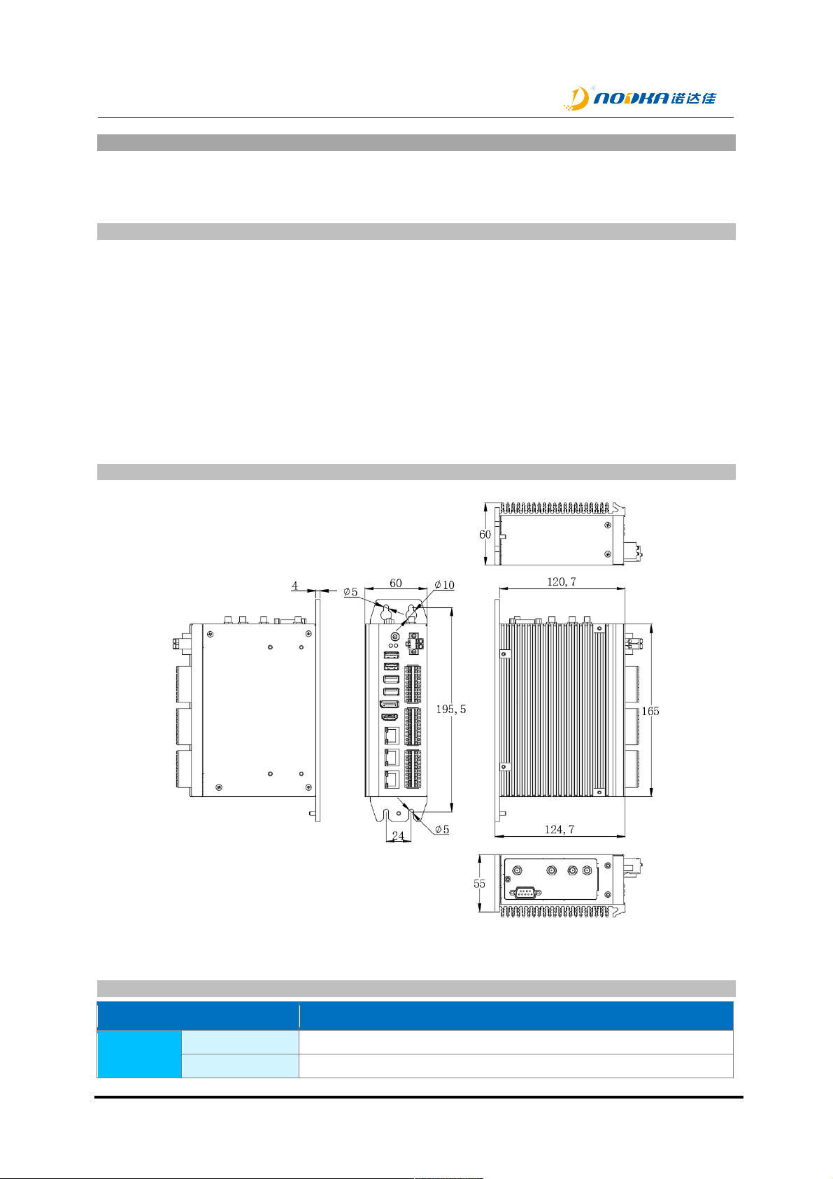
2.1.2 Product Dimension.......................................................................................................... 7!
2.1.3 Product Specifications..................................................................................................... 7!
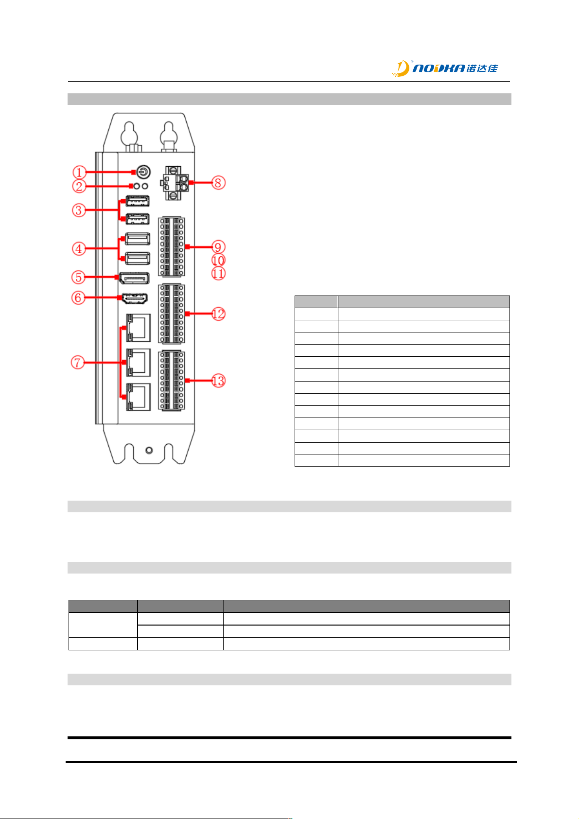
2.1.4 Description of Interfaces ................................................................................................. 9!
2.1.4.1 Power button............................................................................................................. 9!
2.1.4.2 Status Leds............................................................................................................... 9!
2.1.4.3 USB .......................................................................................................................... 9!
USB on the front................................................................................................. 9!2.1.4.3.1
USB2.0 on board.............................................................................................. 10!2.1.4.3.2
2.1.4.4 Display ports........................................................................................................... 11!
DP .................................................................................................................... 11!2.1.4.4.1
HDMI ................................................................................................................ 11!2.1.4.4.2
2.1.4.5 Ethernet .................................................................................................................. 11!
2.1.4.6 Power...................................................................................................................... 12!
2.1.4.7 Serial port and Can port ......................................................................................... 13!
2.1.4.8 DO .......................................................................................................................... 13!
2.1.4.1 DI ............................................................................................................................ 14!
3.!System Setup......................................................................................................................... 16!
3.1 Hardware Setup................................................................................................................... 17!
3.1.1 Attaching wall-mounted part.......................................................................................... 17!
3.1.2 Attaching DIN-Rail mounted part .................................................................................. 17!
3.1.3 SSD Setup .................................................................................................................... 18!
3.1.4 USB dongle Setup......................................................................................................... 19!
3.2 Driver Setup......................................................................................................................... 20!
4.!Safety and Maintenance ........................................................................................................ 21!
4.1 Safety Precautions .............................................................................................................. 22!
4.1.1 General Safety Precautions .......................................................................................... 22!
4.1.2 ESD Precautions........................................................................................................... 22!
4.1.3 Product Disposal ........................................................................................................... 22!
4.2 Maintenance and Cleaning Precautions.............................................................................. 22!
4.2.1 Maintenance and Cleaning ........................................................................................... 23!
4.2.2 Cleaning Tools .............................................................................................................. 23!
5.!Q&A........................................................................................................................................ 24!
5.1 Ditital IO electrical wiring diagram ....................................................................................... 25!
5.1.1 DI electrical wiring diagram ........................................................................................... 25!
5.1.2 DO electrical wiring diagram ......................................................................................... 25!
5.2 How to test the DO using multimeter................................................................................... 25!
5.3 Technical Support and Services.......................................................................................... 25!

NP-6118 Series user manual
Suzhou Nodka Automation Technology Co.,Ltd. | Addr:480 Yinzang Road, Wuzhong District, Suzhou | Tel:0512-66202700
Page: 4 / 25
1. Introduction
This chapter provides necessary information of the product such as the features and
manuals before actual use.

NP-6118 Series user manual
Suzhou Nodka Automation Technology Co.,Ltd. | Addr:480 Yinzang Road, Wuzhong District, Suzhou | Tel:0512-66202700
Page: 5 / 25
1.1 Releated Manuals
The manuals releated to the product are listed below, please read them as necessary along with
this document before acutual use.
Name
Purpose
Contents
How to get
User manual
Must read when
operating the product.
Descrbes the hardware
features and settings
Download from Nodka website.
SDK user manual
Must read when
developing the IO
functions
Describes the API
functions and useage
Download from Nodka website.
1.1 Safety Information
This document provides safety information using the following symbols to prevent accidents
resulting in injury or death and the destruction of equipment and resources. Undersand the
meanings of these symbols to operate the equipment safely.
Symbol
Description
WARNING
WARNING indicates a potentially hazardous situation which, if not avoided,
could result in death or serious injury.
DANGER
DANGER indicates an imminently hazardous situation which, if not avoided, will
result in death or serious injury.
NOTE
NOTE provide the reader with additional information or refer to detailed sources
of information.
1.2 Production Description
NP-6118 and its series products are low-power, fanless, book style exquisite embedded PC in
Nodka Automation PC family. The system is designed following Nodka’s COMLAC modular
concept, which makes the system to be more cost-effective and easily updated. Fanles and no
cable design and enclosed chassis ensure the product stability. To be more, all of the ports are
designed in the front side, which will be very easy to do wiring and maintenance.
NP-6118 is an excellent performance/price ratio platform and has been widely used in the fields
of motion control, smart gateway, instrument collection terminal and automation control.

NP-6118 Series user manual
Suzhou Nodka Automation Technology Co.,Ltd. | Addr:480 Yinzang Road, Wuzhong District, Suzhou | Tel:0512-66202700
Page: 6 / 25
2. Product Introduction
This chapter describes product component and their functions, pin assignment of each connector
in detail.

NP-6118 Series user manual
Suzhou Nodka Automation Technology Co.,Ltd. | Addr:480 Yinzang Road, Wuzhong District, Suzhou | Tel:0512-66202700
Page: 7 / 25
2.1 NP-6118
NP-6118 is basic module in its series and provides various kind of interfaces based on Intel
Celeron J6412 processor, which has been widely used in the fields of motion control, smart
gateway, instrument collection terminal and automation control.
2.1.1 Features
!1 x Intel I211-AT GbE controller
!2 x RTL8111H GbE controller
!4 x USB Type A ports and 1 x Type A on board for dongle installation
!1 x RS232,2 x RS485,RS485 support auto flow control
!2 x CAN2.0 Bus
!16 x isolated DI, 16 x isolated DO
!1 x miniPCIe expansion slot
!1 x M.2 slot for Wifi
!Support Wall-mounted or DIN-Rail mounted
!Support -20 ~ 60℃wide temperature environment
2.1.2 Product Dimension
Unit: mm
Figure 1 Dimension of NP-6118
2.1.3 Product Specifications
Module
NP-6118-16I16OC-J6412
System
CPU
Intel® Celeron J6412, 2.0~2.6GHz, 4 cores/4 threads, 1.5MB L2 cache
TDP
10W

NP-6118 Series user manual
Suzhou Nodka Automation Technology Co.,Ltd. | Addr:480 Yinzang Road, Wuzhong District, Suzhou | Tel:0512-66202700
Page: 8 / 25
BIOS
AMI UEFI 64Mbit
Memory
1 x SO-DIMM DDR4-2400MHz (Max. 16GB)
Storage
1 x mSATA slot
USB
2 x USB3.0, 2 x USB2.0
1 x USB2.0 on board
COM
1 x RS232, 2 x RS485
Ethernet
1 x Intel I211-AT GbE LAN controller
2 x RTL8111H GbE LAN controller
DI
16 x DI NPN/PNP, isolated voltage:2500Vrms
DO
16 x DO, Transistor output,Imax: 500mA, isolated voltage: 2500Vrms
CAN
2 x CAN Bus 2.0A/B
HDMI
Support up to 4096 x 2160
DP
Support up to 4096 x 2160
Expansion
1 x full-size miniPCIe slot with SIM slot
1 x M.2 KEY-A for Wifi
Watchdog
1~255 levels programable
OS
Microsoft Windows
Windows 10 IoT
Linux
Ubuntu
Power
Voltage Input
DC12~24V ±10%, overcurrent, overvoltage and polarity inverse protection, (internal UPS
is optional)
Power Consumption
Max. 45W
Chassis
Structure
Fanless, support Wall-mounted or DIN-Rail mounted
Dimensions
(L)165mm x (W)124.7mm x (H)60mm
Net Weight
2.1Kg
Environment
Work Temperature
-20ºC ~ 60ºC (-4℉~140℉) with air flow (SSD)
Storage Temperature
-40ºC ~ 80ºC (-40℉ ~ 176℉) with air flow (SSD)
Relative Humidity
5~95% (Non-condensing)
Operating Vibration
5~500Hz, 1.5Grms@with SSD, Follow IEC60068-2-64
Operating Shock
20G peak acceleration(11ms duration) with SSD, Follow IEC60068-2-27
EMC
CE/FCC Class A

NP-6118 Series user manual
Suzhou Nodka Automation Technology Co.,Ltd. | Addr:480 Yinzang Road, Wuzhong District, Suzhou | Tel:0512-66202700
Page: 9 / 25
2.1.4 Description of Interfaces
No.
Name
1
Power button
2
Status Leds
3
USB2.0
4
USB3.0
5
DP
6
HDMI
7
Ethernet
8
DC_IN
9
CAN
10
RS232
11
RS485
12
DO
13
DI
Figure 2 Interfaces of NP-6118
2.1.4.1 Power button
The product provides a power button with power led on the front, which can be used to turn on or
turn off the PC in the case of power supply is connected.
2.1.4.2 Status Leds
The product provides two status leds on the front to indicate the status of the power and the
storage disk operation.
LED
Status
Description
Power Led
off
The product is power on
on(Green)
The product is power off
Disk Led
blink(Orange)
The disk is reading or writing
2.1.4.3 USB
The product provide four USB TYPE-A ports on the front and one USB TYPE-A port on the board
can be used to install the USB dongle.
USB on the front2.1.4.3.1

NP-6118 Series user manual
Suzhou Nodka Automation Technology Co.,Ltd. | Addr:480 Yinzang Road, Wuzhong District, Suzhou | Tel:0512-66202700
Page: 10 / 25
NP-6118 provide two USB3.0 ports and two USB2.0 ports on the front when using Intel Celeron
J6412 processor.
Pin definition of USB3.0 port:
Pin No.
Signals
1
VCC5
2
DATA-
3
DATA+
4
GND
5
SSRX-
6
SSRX+
7
GND
8
SSTX-
9
SSTX+
Pin definition of USB2.0 port:
Pin No.
Signals
1
VCC5
2
DATA-
3
DATA+
4
GND
USB2.0 on board2.1.4.3.2
The product provides a USB2.0 on board which can be used for USB dongle. It can be seen after
four screws in the aluminum radiator are unscrewed. Please refer to the blue area in the below
figure.
Figure 3 USB2.0 on board
Pin definition of USB2.0 port on board:
Pin No.
Signals
1
VCC5
2
DATA-
3
DATA+
4
GND

NP-6118 Series user manual
Suzhou Nodka Automation Technology Co.,Ltd. | Addr:480 Yinzang Road, Wuzhong District, Suzhou | Tel:0512-66202700
Page: 11 / 25
2.1.4.4 Display ports
The product supports both DP and HDMI HD display ports.
DP2.1.4.4.1
Pin definition of DP connector:
DP Connector
Pin No.
Siganls
Pin No.
Signals
1
ML_Lane 0(p)
2
GND
3
ML_Lane 0(n)
4
ML_Lane 1(p)
5
GND
6
ML_Lane 1(n)
7
ML_Lane 2(p)
8
GND
9
ML_Lane 2(n)
10
ML_Lane 3(p)
11
GND
12
ML_Lane 3(n)
13
GND
14
GND
15
AUX_CH(p)
16
GND
17
AUX_CH(n)
18
Hot Plug
19
DP_PWR_Return
20
Power
HDMI2.1.4.4.2
Pin definition of HDMI connector:
HDMI TYPE-A Connector
Pin No.
Signals
Pin No.
Signals
1
TMDS DATA 2+
11
TMDS CLOCK SHIELD
2
TMDS DATA 2 SHIELD
12
TMDS CLOCK-
3
TMDS DATA 2-
13
CEC
4
TMDS DATA 1+
14
N.C.
5
TMDS DATA 1 SHIELD
15
DDC CLOCK
6
TMDS DATA 1-
16
DDC DATA
7
TMDS DATA 0+
17
GND
8
TMDS DATA 0 SHIELD
18
+5V PWR
9
TMDS DATA 0-
19
HOT PLUG DETECT
10
TMDS CLOCK+
2.1.4.5 Ethernet
The product provides three GbE Lan controllers using standard RJ45 connectors, they are LAN1,
LAN2 and LAN3.
Pin definition of RJ45 connector:
Pin No.
Siganls
100BASE-TX
1000BASE-T
1
TX+
TRD+(0)
2
TX-
TRD-(0)
3
RX+
TRD+(1)
4
N.C.
TRD+(2)
5
N.C.
TRD-(2)

NP-6118 Series user manual
Suzhou Nodka Automation Technology Co.,Ltd. | Addr:480 Yinzang Road, Wuzhong District, Suzhou | Tel:0512-66202700
Page: 12 / 25
6
RX-
TRD-(1)
7
N.C.
TRD+(3)
8
N.C.
TRD-(3)
There are two status leds in the RJ45 connector indicate the status of the link and transmit
separately. Link led is on when link successfully, and when the network is working in the
1000Mbps, the transmit led is blinking in orange color and in green color when working in the
other speed.
Items
Parameters
Network type
1000BASE-T/100BASE-TX/10BASE-T
Transmission speed*
1000M/100M/10M bps
Max. network path length
100m/segment
*Operation at 1000Mbps requires a category 5e or greater cable.
2.1.4.6 Power
The product support DC12V~24V wide voltage input.
Pin definition of DC IN connector:
Pin No.
Signal
Pin No.
Signal
1
GND
2
DC 12~24V
:
1. Must check whither the voltage output of the power supply matches the PC
DC input before connecting to the PC.
2. Must check the positive and negative pole marks on the housing before
connecting to the power.
3. Must turn off the power before inserting or removing the boards or cables.
4. PE should be well grounded when operating.
5. Must do not connect AC power supply to the PC directly.

NP-6118 Series user manual
Suzhou Nodka Automation Technology Co.,Ltd. | Addr:480 Yinzang Road, Wuzhong District, Suzhou | Tel:0512-66202700
Page: 13 / 25
2.1.4.7 Serial port and Can port
The product provides three serial ports and two CAN bus ports as the phoenix connector on the
front.
Pin definition of the communication connector:
Pin No.
Signals
Description
Pin No.
Siganls
Description
20
C2L
CH2_CAN_L
19
C2H
CH2_CAN_H
18
C1L
CH2_CAN_L
17
C1H
CH1_CAN_H
16
CGnd
CAN Gnd
15
CGnd
CAN Gnd
14
RX*
COM3 RS232_RX
13
TX*
COM3 RS232_TX
12
A2*
COM2 RS485_A
11
B2*
COM2 RS485_B
10
A1*
COM1 RS485_A
9
B1*
COM1 RS485_B
8
Gnd
GND
7
Gnd
GND
6
R_STS
DO
5
P_OK
DI
4
P_STS
Power On status
3
SW
Remote switch on/off
2
SGnd
Signal GND
1
SGnd
Signal GND
*The serial port COM1, COM2 and COM3 are enumerated as ‘/dev/ttyS0’, ‘/dev/ttyS1’ and ‘/dev/ttyS2’ in the
Linux operating system.
2.1.4.8 DO
The product provides 16 Digital Output channels, transistor output, Imax: 500mA, Vmax: 50V.
Please remind that a diode shall be connected in parallel for freewheeling when external
inductive load is connected.
Pin definition of the DO connector:
Pin No.
Signals
Function
Pin No.
Signals
Function
20
Y0
DO_CH0
19
Y8
DO_CH8
18
Y1
DO_CH1
17
Y9
DO_CH9
16
Y2
DO_CH2
15
Y10
DO_CH10
14
Y3
DO_CH3
13
Y11
DO_CH11
12
Y4
DO_CH4
11
Y12
DO_CH12
10
Y5
DO_CH5
9
Y13
DO_CH13
8
Y6
DO_CH6
7
Y14
DO_CH14
6
Y7
DO_CH7
5
Y15
DO_CH15
4
YGnd
DO_GND
3
YGnd
DO_GND
2
YGnd
DO_GND
1
YGnd
DO_GND
Wiring:
Figure 4 Wiring of resistive load

NP-6118 Series user manual
Suzhou Nodka Automation Technology Co.,Ltd. | Addr:480 Yinzang Road, Wuzhong District, Suzhou | Tel:0512-66202700
Page: 14 / 25
Figure 5 Wiring of inductive load
:
1. DO output load current is not allowed to exceed the maximum current of
500mA.
2. The maximum DO load voltage is not allowed to exceed 50VDC.
3. Must don’t connect the Power positive pole to the DO pin or DO GND
directly.
2.1.4.1 DI
The product provides 16 isolated Digital input channels, which support both NPN and PNP wiring
solutions.
Pin definition of the DI connector:
Pin No.
Signals
Function
Pin No.
Signals
Function
20
X0
DI_CH0
19
X8
DI_CH8
18
X1
DI_CH 1
17
X9
DI_CH9
16
X2
DI_CH 2
15
X10
DI_CH10
14
X3
DI_CH 3
13
X11
DI_CH11
12
X4
DI_CH 4
11
X12
DI_CH12
10
X5
DI_CH 5
9
X13
DI_CH13
8
X6
DI_CH 6
7
X14
DI_CH14
6
X7
DI_CH 7
5
X15
DI_CH15
4
XCom
DI_COM
3
XCom
DI_COM
2
XCom
DI_COM
1
XCom
DI_COM
"NPN wiring solution
Figure 6 DI NPN wiring solution
"PNP wiring solution

NP-6118 Series user manual
Suzhou Nodka Automation Technology Co.,Ltd. | Addr:480 Yinzang Road, Wuzhong District, Suzhou | Tel:0512-66202700
Page: 15 / 25
Figure 7 DI PNP wiring solution

NP-6118 Series user manual
Suzhou Nodka Automation Technology Co.,Ltd. | Addr:480 Yinzang Road, Wuzhong District, Suzhou | Tel:0512-66202700
Page: 16 / 25
3. System Setup
This chapter mainly introduces how to setup hardware components drivers.

NP-6118 Series user manual
Suzhou Nodka Automation Technology Co.,Ltd. | Addr:480 Yinzang Road, Wuzhong District, Suzhou | Tel:0512-66202700
Page: 17 / 25
3.1 Hardware Setup
3.1.1 Attaching wall-mounted part
Use 4 screws on the back to attach the wall-mounted part, please refer to the below figure.
Figure 8 Attach the wall-mount part
:
1. Do not tighten screws with excess force.
2. Screw holes may be damaged if screws are tightened with a torque greater
than the specified torque. The specified tightening torque is 5-6 kgf⋅cm.
3.1.2 Attaching DIN-Rail mounted part
Use 4 screws on the back to attach the DIN-Rail mounted part, please refer to the below figure.
Figure 9 Attach DIN-Rail mounted part

NP-6118 Series user manual
Suzhou Nodka Automation Technology Co.,Ltd. | Addr:480 Yinzang Road, Wuzhong District, Suzhou | Tel:0512-66202700
Page: 18 / 25
:
1. Do not tighten screws with excess force.
2. Screw holes may be damaged if screws are tightened with a torque greater
than the specified torque. The specified tightening torque is 5-6 kgf⋅cm.
3.1.3 SSD Setup
1. Unscrew four screws(①~④) in the aluminum radiator.
2. Remove the aluminum radiator(⑤), please be care of the thermal grease not to be damaged.
3. Then you can install or uninstall the SSD(⑥).
Figure 10 SSD Setup
:
1. Must disconnect the power supply before operating.
2. Pay attention to electrostatic discharge.
3. Do not tighten screws with excess force.

NP-6118 Series user manual
Suzhou Nodka Automation Technology Co.,Ltd. | Addr:480 Yinzang Road, Wuzhong District, Suzhou | Tel:0512-66202700
Page: 19 / 25
3.1.4 USB dongle Setup
1. Unscrew four screws(①~④) in the aluminum radiator.
2. Remove the aluminum radiator(⑤), please be care of the thermal grease not to be damaged.
3. Then you can install or uninstall the USB device(⑦).
Figure 11 USB dongle Setup
This manual suits for next models
1
Table of contents
Other Nodka Industrial PC manuals