NoiseKen LSS-F02 Series User manual

INSTRUCTIONMANUAL
LIGHTNINGSURGESIMULATOR
MODEL
LSS-F02 SERIES
NOISE LABORATORY CO., LTD.
The 2.04 edition
AEE00499-00E-1E

NOTICE
•The contents of this instruction manual (the “Manual”) are subject to change
without prior notice.
•No part of the Manual may be reproduced or distributed, in any form or by any
means, without the authorization of Noise Laboratory Co., Ltd. (the “Company”).
•The contents of the Manual have been thoroughly examined. However, if you find
any problems, misprints, or missing information, please feel free to contact our
sales agent who you purchased our product from.
•The Company assumes no responsibility for any loss or damage resulting from
improper usage, failure to follow the Manual, or any repair or modifications of this
product undertaken by a third party other than the Company or the agent
authorized by the Company.
•
The Company assumes no responsibility for any loss or damage resulting from
remodeling or conversion solely undertaken by the user.
•
Please note that the Company cannot be held responsible for any consequences
arising from the use of this product.

1
Only well-trained EMC technicians (electric technicians) are
allowed to use the Unit.
The Unit may cause a fatal wound. Carefully handle it. And it may radiate
electromagnetic noise which exceeds the regulation value. Take applicable
countermeasures such as faraday cage, shield room, etc. as the need arises.
The Unit should be used only for EMC testing described in
this manual.
Using it for other purposes may result in a fatal or serious accident.
A person who has a pacemaker on should not operate the
Unit and also should not enter the area where it is operating.
It may result in a fatal or serious accident.
The Unit cannot be used in an explosive area, fire prohibited
area, etc.
Use of the Unit in such an area is liable to cause combustion or ignition.
1. IMPORTANT SAFETY PRECAUTIONS
The following instructions are very important for safe handling of the lightening surge
simulator LSS-F02 series (hereinafter “the Unit”). They must be kept strictly to prevent
users of the Unit from receiving harm or damage through using the Unit. Read them
carefully before use.
A number of safety recommendations are listed in the later chapter
"BASIC SAFETY PRECAUTIONS". Be sure to read them before test
environment settings, connecting relating equipment and testing.

2
2. CHECK PACKAGE CONTENTS
Before using the instrument, check whether the included accessories are
complete according to the following list.
A B C D
E F G H
I J K L
A:AC cable--------------------------------------------------------------------------------------------- 1
B:Surge output cable (1.8m) (MODEL:05-00137A alligator clip)--------------- 2
C:Line output cable (1.8m) (MODEL:05-00138A M6)----------------------------- 3(A1A/C1)
5(A3A/C3)
D:FG cable (2m) (MODEL:05-00070A M6-M6)----------------------------------- 1
E:Coaxial cable for monitoring (1m) (MODEL:02-00128A BNC-BNC)------ 1
F:Interlock connector-------------------------------------------------------------------------------- 1
G:High voltage connector cap(MODEL:05-00060A)--------------------------------- 5(A1A/C1)
7(A3/AC3)
H:Telecom line output cable (1m) (MODEL:05-00061A/05-00065A)---------- 5(C1/C3)
I:Coupling arrestor unit (for coupling) (MODEL:08-00016A)----------------------- 4(C1/C3)
J:Arrestor unit (For input protection) (MODEL:08-00012A)------------------------ 4(C1/C3)
K:Accessory bag------------------------------------------------------------------------------------- 1
L:Instruction manual--------------------------------------------------------------------------------- 1

3
3. APPLICATION FORM FOR INSTRUCTION MANUAL
We place an order for an instruction manual.
Model: LSS-F02
Serial No.:
Applicant:
Company name:
Address:
Department:
Person in charge:
Tel No.:
Fax No.
Cut off this page “APPLICATION FORM FOR INSTRUCTION
MANUAL” from this volume and keep it for future use with
care.
When an INSTRUCTION MANUAL is required, fill in the above Application Form and
mail or fax it to the following sales department of our company.
To: Noise Laboratory Co., Ltd.
1-4-4 Chiyoda, Chuo-ku, Sagamihara City,
Kanagawa Pref., 252-0237 Japan
Tel: +81-(0)42-712-2051 Fax: +81-(0)42-712-2050
Cut
line

Memorandum
4

5
4. PREFACE
4-1. Preface
We thank you very much for your purchase of our Lightening Surge Simulator LSS-F02
series (hereinafter “the Unit”). This instruction manual (“the Manual”) contains how to use
the Unit and other important information. In order to obtain the highest performance from
the Unit, thoroughly understand the contents of the Manual and use as ready reference
for operation.
The Manual was prepared so that any person who can observe the prescribed instruction
method and operating precautions may safely handle and fully utilize the Unit.
Keep the Manual by your side or other proper location so that it may be readily available
when using the Unit.
4-2. Feature
Conforming to IEC61000-4-5 (Edition 2.0 / 2005)
Generating combination wave surge of 1.2/50µs and 10/700µs prescribed by IEC 61000-4-5
(Edition 2 / 2005).
Combination waves mean output of 1.2/50µs or 10/700µs voltage surge waveform with the
surge output unit opened (load: more than 10kΩ) and output of 8/20µs or 5/320µs current
surge waveform with the output unit short-circuited.
Testing high voltage and great electric current (voltage surge: 15kV, current surge: 7500A).
The surge generating circuit adopts a floating output system recommended by IEC
61000-4-5 (Edition 2 / 2005).
Capable to conduct surge injection test to power supply lines with the CDN (Coupling and
Decoupling Network) for EUT which is equipped as standard equipment. The AC/DC line
injection part adopts a circuit system conforming to IEC 61000-4-5 (Edition 2 / 2005).
Capable to conduct surge injection test to TELECOM lines with the incorporated CDN for the
symmetrical interconnection lines (C1 / C3 model).
User-friendlyLCD ControlPanel
The operation panel adopts a color LCD touch panel for pursuing high visibility.
Capableofvariouskindsofsetupwithsimpletouchpanel.
Employspushbuttonsforhandlingsafety-relatedoperationsuchasSTART/STOP.
Various Functions BroadenHorizonsofTest
Preset test conditions which are prescribed on the standard in the “standard test” mode.
Capable to set test conditions as you like in the “manual test” mode.
“Sweep” function enable automatic step-by-step change of test parameters.
Capable to save your test conditions.
Remote control is available with optical communication (optional).
Capable to set upper limit of voltage setup (6kV).

6
5. CONTENTS
1. IMPORTANT SAFETY PRECAUTIONS..................................................................... 1
2. CHECK PACKAGE CONTENTS................................................................................ 2
3. APPLICATION FORM FOR INSTRUCTION MANUAL.............................................. 3
4. PREFACE................................................................................................................... 5
4-1.
P
REFACE
·······················································································································5
4-2.
F
EATURE
·······················································································································5
5. CONTENTS................................................................................................................ 6
6. BASIC SAFETY PRECAUTIONS............................................................................... 9
6-1.
S
YMBOLS OF
H
AZARD
········································································································9
6-2.
S
YMBOLS OF
I
NSTRUCTION
,
W
ARNING AND
C
AUTION
···································································9
7. CAUTION ABOUT EXPENDABLE SUPPLIES........................................................ 16
8. INTRODUCTORY NOTES........................................................................................ 17
8-1.
I
NTRODUCTORY
N
OTES
···································································································· 17
8-2.
T
ERMS AND
D
EFINITIONS
·································································································· 17
8-3.
H
OW TO
U
NDERSTAND
M
ODEL
N
UMBER
················································································ 18
8-4.
D
EFINITION OF
S
URGE
W
AVEFORM
······················································································ 18
V
OLTAGE
S
URGE
W
AVEFORM
.................................................................................................................. 18
C
URRENT
S
URGE
W
AVEFORM
................................................................................................................. 18
8-5.
B
LOCK
D
IAGRAM
············································································································ 19
9. APPEARANCE AND FUNCTION OF EACH PART ................................................. 20
9-1.
A
PPEARANCE OF
T
HE
M
AIN
U
NIT
························································································· 20
9-2.
C
ONTROL
P
ANEL
············································································································ 22
9-3.
S
URGE
G
ENERATION
P
ANEL
······························································································ 23
9-4.
AC/DC
L
INE
I
NJECTION
P
ANEL
··························································································· 24
S
INGLE
P
HASE
M
ODEL
(A1A/C1
TYPE
).................................................................................................... 24
T
HREE
P
HASE
M
ODEL
(A3A/C3
TYPE
)..................................................................................................... 24
9-5.
T
ELECOM
L
INE
I
NJECTION
P
ANEL
(C1/C3) ············································································· 26
9-6.
I
NPUT
P
ANEL
················································································································· 28
S
INGLE
P
HASE
M
ODEL
(A1A/C1
TYPE
).................................................................................................... 28
T
HREE
P
HASE
M
ODEL
(A3A/C3
TYPE
)..................................................................................................... 28
10. CONNECTION........................................................................................................ 30
10-1.
C
ONNECTION OF
AC
C
ABLES AND
I
NTERLOCK
C
ONNECTOR
······················································· 30
10-2.
C
ONNECTION OF
O
PTICAL
C
OMMUNICATION
C
ABLE
(O
PTIONAL
)·················································· 31
10-3.
C
ONNECTION FOR
A
PPLYING
S
URGE
W
AVEFORM TO
EUT
D
IRECTLY
············································ 32

5. CONTENTS
7
C
ONNECTION OF
S
URGE
O
UTPUT
............................................................................................................ 32
10-4.
C
ONNECTION FOR
A
PPLYING
S
URGE
W
AVEFORM TO
AC/DC
L
INE
··············································· 33
C
ONNECTION OF
AC/DC
L
INE
I
NPUT
........................................................................................................ 33
C
ONNECTION OF
AC/DC
L
INE
O
UTPUT
.................................................................................................... 35
10-5.
C
ONNECTION FOR
A
PPLYING
S
URGE
W
AVEFORM TO
T
ELECOM
L
INE
(C1/C3)································· 37
C
ONNECTION OF
T
ELECOM
L
INE
I
NPUT
..................................................................................................... 37
C
ONNECTION OF
T
ELECOM
L
INE
O
UTPUT
................................................................................................. 37
11. OPERATION............................................................................................................40
11-1.
E
MERGENCY
S
TOP
B
UTTON
····························································································· 40
11-2.
T
URN
ON
THE
U
NIT
······································································································· 41
11-3.
M
AIN
M
ENU
················································································································ 41
11-4.
S
CREEN
F
LOWCHART
····································································································· 42
11-5.
I
NPUTTING
N
UMBERS AND
L
ETTERS
(A
BOUT
T
EN
K
EY AND
C
HARACTER
K
EY
) ································· 43
12. STANDARD TEST...................................................................................................44
12-1.
S
ETTING
S
TANDARD
T
EST
······························································································· 44
D
ISCHARGE
I
NTERVAL
............................................................................................................................. 46
12-2.
AC
LINE
S
TANDARD
····································································································· 46
12-3.
DC
LINE
S
TANDARD
····································································································· 47
12-4.
ENCLOSURE
S
TANDARD
······························································································ 47
12-5.
TELECOM
S
TANDARD
(C1/C3
TYPE
) ················································································ 48
12-6.
E
XECUTING
S
TANDARD
T
EST
··························································································· 49
13. MANUAL TEST.......................................................................................................54
13-1.
S
ETTING
M
ANUAL
T
EST
·································································································· 54
S
ELECTING
O
UTPUT
................................................................................................................................ 56
S
ELECTING
S
YNCHRONIZATION
(P
HASE
A
NGLE
)
/
S
YNCHRONIZATION
........................................................ 57
S
ELECTING
W
AVEFORM
........................................................................................................................... 58
S
ELECTING
P
OLARITY
.............................................................................................................................. 58
S
ETTING
V
OLTAGE
.................................................................................................................................. 59
S
ETTING
D
ISCHARGE
T
IMES
.................................................................................................................... 60
S
ETTING
I
NTERVAL
.................................................................................................................................. 60
13-2.
S
ETTING
AC/DC
I
NJECTION
····························································································· 61
13-3.
S
ETTING
TELECOM
I
NJECTION
(C1/C3
TYPE
)······································································ 64
13-4.
E
XECUTING
M
ANUAL
T
EST
······························································································ 67
14. TITLE SAVE / LOAD...............................................................................................71
S
AVE
...................................................................................................................................................... 72
C
HANGING
T
ITLE
..................................................................................................................................... 72
L
OAD
...................................................................................................................................................... 73
D
ELETE
.................................................................................................................................................. 73
15. UTILITY...................................................................................................................74

5. CONTENTS
8
P
OWER
ON
D
ISPLAY
............................................................................................................................... 74
A
LARM
B
EEP
........................................................................................................................................... 74
L
ANGUAGE
.............................................................................................................................................. 74
V
OLTAGE
L
IMIT
....................................................................................................................................... 74
I
NTERLOCK
L
EVEL
................................................................................................................................... 75
S
EQUENCE
M
ETHOD
................................................................................................................................ 75
T
ITLE
O
PERATION
................................................................................................................................... 75
16. ERROR MESSAGE................................................................................................ 76
17. SPECIFICATIONS.................................................................................................. 78
17-1.
C
ONTROLLING
P
ART
······································································································ 78
17-2.
S
URGE
G
ENERATING
P
ART
······························································································ 78
17-3.
AC
/
DC
L
INE
I
NJECTION
P
ART
·························································································· 79
17-4.
T
ELECOM
L
INE
I
NJECTION
P
ART
(C1/C3
T
YPE
)······································································ 80
17-5.
G
ENERAL
S
PECIFICATIONS
······························································································ 80
18. OPTIONAL PRODUCT........................................................................................... 81
19. WAVEFORM VERIFICATION................................................................................. 82
19-1.
P
REPARATION
·············································································································· 82
19-2.
C
ONNECTION
··············································································································· 82
19-3.
N
OTICE FOR
O
BSERVING AT
M
ONITOR
T
ERMINAL
···································································· 82
H
OW TO OBSERVE AT
M
ONITOR
T
ERMINAL
............................................................................................... 82
15-4.
M
EASUREMENT
············································································································ 83
19-5.
W
HY
PE
OF
O
SCILLOSCOPE
S
HOULD
N
OT BE
C
OMMON WITH
E
ARTH OF THE
U
NIT
···························· 83
20. WARRANTY........................................................................................................... 84
21. MAINTENANCE ..................................................................................................... 86
22. NOISE LABORATORY SUPPORT NETWORK..................................................... 87
9
6. BASIC SAFETY PRECAUTIONS
The following items are very important instructions which users must follow to take
precautions against possible injury and harm.
The indications are provided as an explanation of potential danger involved if the
safety precautions are not observed correctly.
6-1. Symbols of Hazard
The following display classifications describe degree, to which injury or harm might occur
when the contents of the display are not followed or the Unit or related equipment is
operated incorrectly.
DANGER
The contents of this display indicate “the assumption that imminent danger might occur
resulting in death or serious injury” if the Unit or related equipment is handled incorrectly.
WARNING
The contents of this display indicate “the assumption that there is a possibility of death or
serious injury” if the Unit or related equipment is handled incorrectly.
CAUTION
The contents of this display indicate “the assumption that there is a possibility of harm
and the assumption that there is a possibility of physical damage” if the Unit or related
equipment is handled incorrectly.
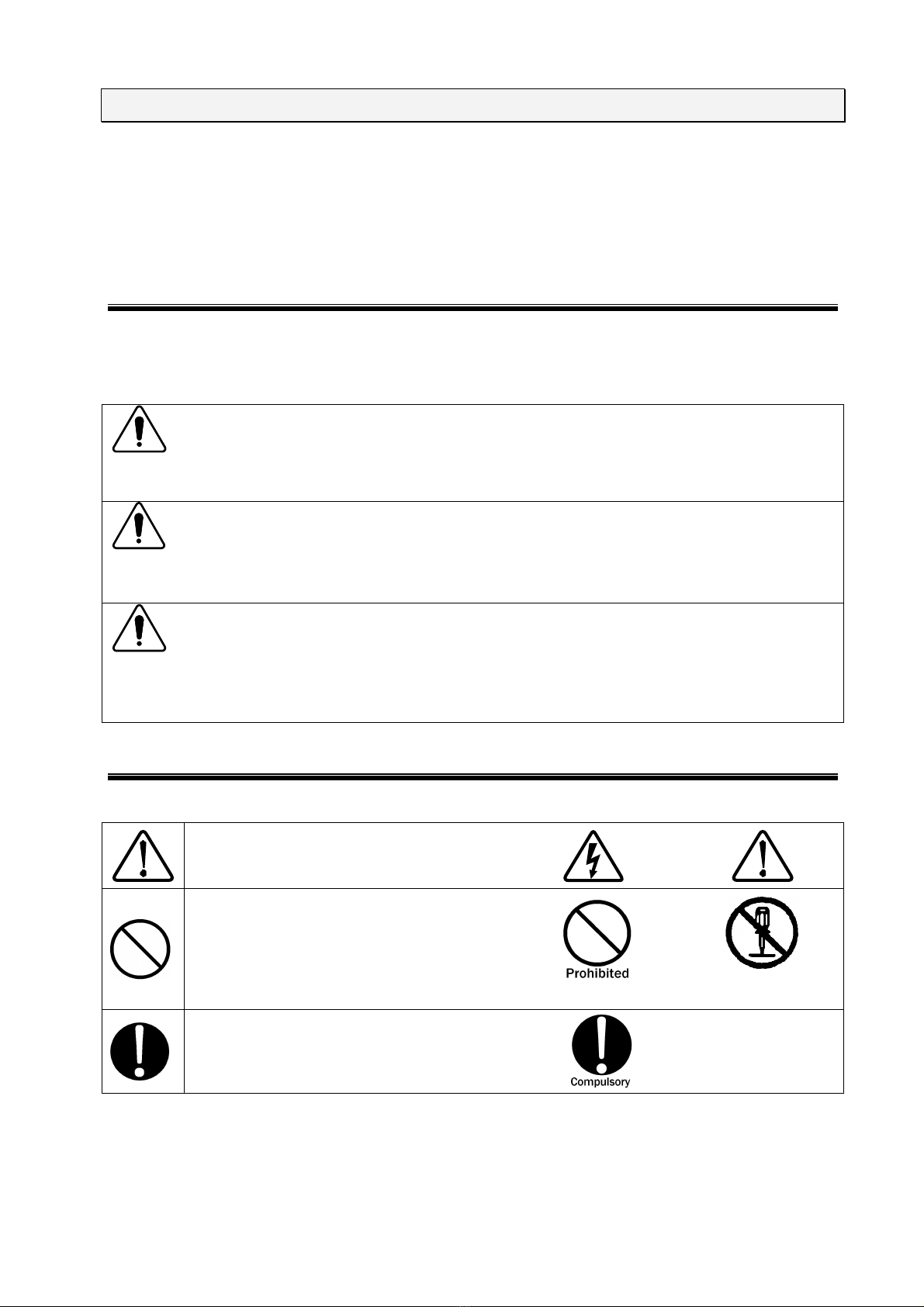
6-2. Symbols of Instruction, Warning and Caution
The following display classifications describe details that should be followed.
Indicates attention (a matter that must be
paid attention fully)
Indicates prohibition (an action that must
not be taken)
Do not
disassemble
Indicates a compulsory action (an action
that must be taken)
6. BASIC SAFETY PRECAUTIONS
10
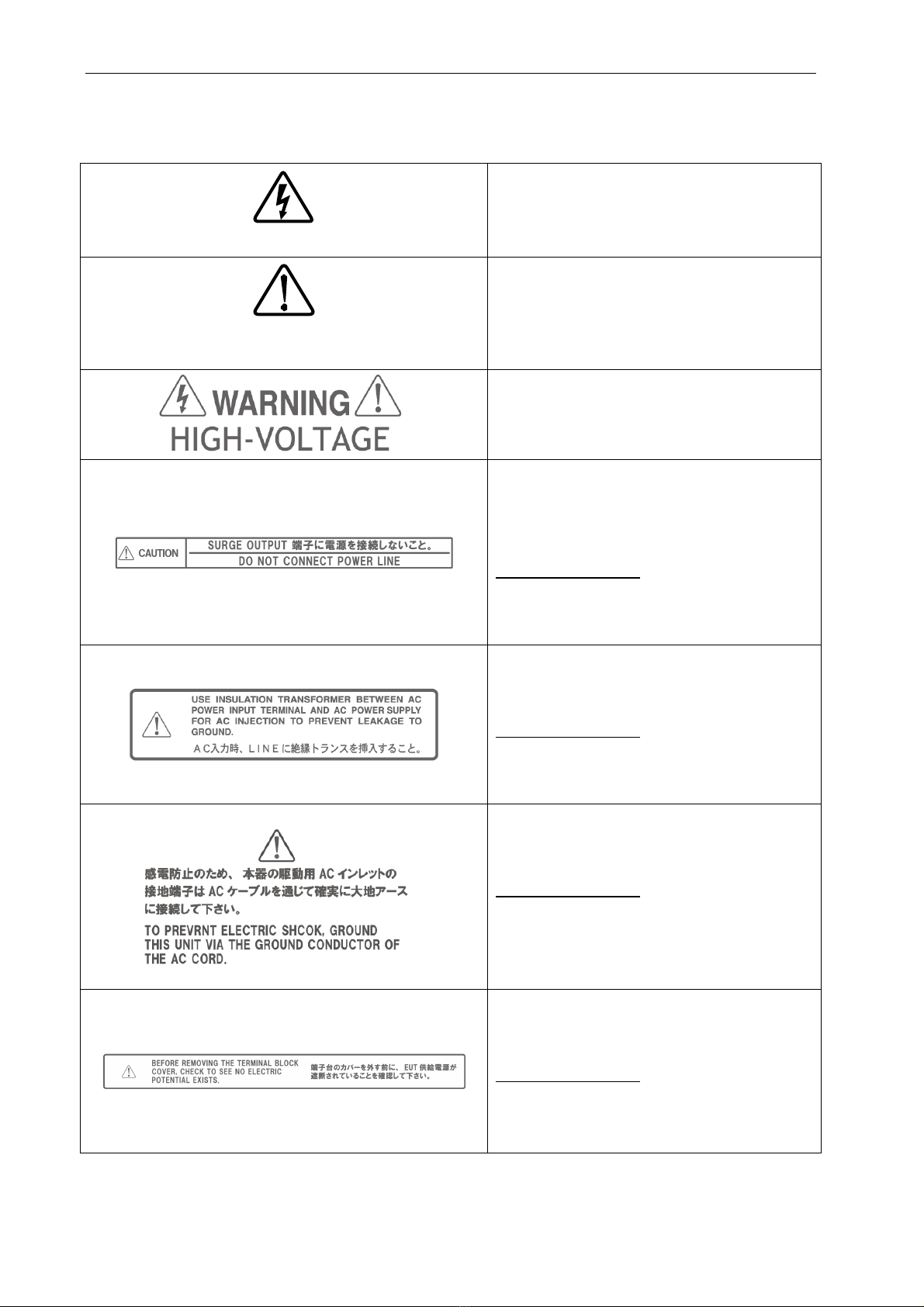
The contents of following signs indicate warnings and cautions when using the Unit.
Noticing possibility of an electric
shock
It indicates that there is possibility of an
electric shock.
Noticing caution, warning and danger
It indicates that there is a possibility of
harm or physical damage if the Unit is or
related equipment is handled incorrectly
and that the Manual should be referred.
It indicates warnings for electric shock etc.
and the Manual should be referred.
It indicates warnings for electric shock etc.
and the Manual should be referred.
Caution on handling
Do not connect power lines to the terminal.
Failure to follow this instruction may result in
damage of the Unit.
It indicates warnings for electric shock etc.
and the Manual should be referred.
Caution on handling
Insert an isolation transformer between the
AC power input terminal of the Unit and the
power supply.
It indicates warnings for electric shock etc.
and the Manual should be referred.
Caution on handling
To prevent an electric shock, ground the
Unit securely with the ground conductor of
the AC cable.
It indicates warnings for electric shock etc.
and the Manual should be referred.
Caution on handling
Before uncovering the terminal block cover,
check to see no electric potential exists.
6. BASIC SAFETY PRECAUTIONS
11
It indicates warnings for electric shock etc.
and the Manual should be referred.
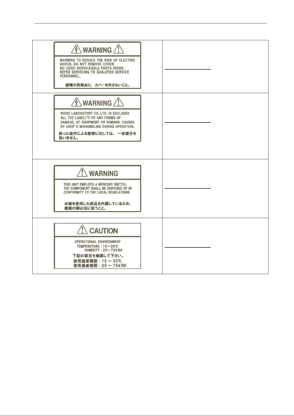
Caution on handling
Do not uncover to reduce the risk of an
electric shock.
It indicates warnings for electric shock etc.
and the Manual should be referred.
Caution on handling
Noise Laboratory Co., Ltd. is excluded all
the liability of any forms of damage, of
equipment or humans, caused by user’s
mishandling during operation.
It indicates warnings for electric shock etc.
and the Manual should be referred.
Caution on handling
The Unit employs a mercury switch. The
component shall be disposed of in
conformity to the local regulation.
It indicates warnings for electric shock etc.
and the Manual should be referred.
Caution on handling
Operational temperature:15~35℃
Operational humidity:25~75%RH

6. BASIC SAFETY PRECAUTIONS
12
DANGER
Do not
disassemble
Do not take the Unit apart or do not remodel. Do not open the cover.
Imminent danger might occur resulting in death or serious injury. Repair, internal
adjustment, and inspection of the Unit should be performed by a qualified service
engineer.Ask the Company or its sales agent.
Do not use the Unit in an explosive are or fire-prohibited area etc.
Use of the Unit in such an area is liable to cause combustion or ignition.
A person who has a pacemaker on should not operate the Unit and also
should not enter the area where it is operating.
It may result in a fatal or serious accident.
WARNING
Stop operation if following unusual phenomena should occur.
Emitting fumes, or smelling.
Water or an unusual substance being stuck
Being dropped or being damaged
AC cable being damaged (e.g. core lines being exposed etc.)
Continuing to operate in the above status may result in a fire, electric shock, or injury. If
an unusual phenomenon occurs, turn off power supply immediately, pull AC plug out of
an outlet, and ask the Company or sales agent repair. As there is potential danger, any
user must not repair the product.
Insulate and protect the test facility against maximum output voltage of
the Unit.
If the test facility is not so insulated and protected, there is the dangerous possibility of
an electric shock, leak or fire.
Turn off power supply of the Unit when setting or changing connection of
related equipment.
Failure to follow this notice may cause electric shock, injury, or malfunction.
Fully pay attention to insulation of surge return route also.
The surge generating circuit of the Unit adopts floating system.
Since the return route is
not connected to the chassis, high voltage may generate on the return route.

6. BASIC SAFETY PRECAUTIONS
13
Use the Unit after understanding instructions in the Manual fully.
There may be danger causing a fatal or serious wound or emitting over-ristricted-value
electromagnetic noise in using the Unit. NOISE LABORATORY and its sales agents
shall have no liability against any accident resulting in injury or death, any damage to
equipment or any resultant damage thereof, which is caused by abuse or careless
handling of this unit.
Watch equipment while the Unit is operating.
If this instruction should not be followed, a third person or equipment related to the test
may be exposed to a danger.
Supply power within the indicated range.
Failure to follow this instruction may cause an electric shock or a fire. The attached AC
cord in the accessory is for AC100~120V.
Use proper connectors and cables and connect them securely.
Avoid using a damaged connector or cable. The misuse may cause an electric shock or
damage of equipment.
Insert AC plug securely to the end.
Insecure inserting generates heat and gathers dust. It may result in a fire or an electric
shock. Avoid using a multiple outlet extension plug for the same reason.
Install the Unit on a stable place.
If the Unit is installed on an unstable place, human body may be in danger due to drop
or overturn of the Unit.
Connect the protective earth of the Unit.
Prepare a proper 3-line AC cable with a protective earth pin conforming to the local
safety standard and connect it to the protective earth of the test room securely. Unless
grounding from the power supply is available, utilize the FG terminal on the rear panel
for grounding.
Be sure to insert an isolation transformer between LINE IN of the Unit and
AC LINE power supply for AC LINE Injection test.
If AC LINE power is supplied to the Unit directly, a circuit breaker installed on the power
supply may function due to leak current from the Unit.
Do not turn on the circuit protector on the input panel while the emergency
button is pressed.
Failure to follow this instruction may cause destruction of the Unit.
In the telecom line surge injection test, be sure to avoid connecting the
telephone switchboard to the telecom line input terminal block.
Failure to follow this instruction may cause destruction of the telephone switchboard
due to surge back from the Unit.

6. BASIC SAFETY PRECAUTIONS
14
WARNING
Do not use the Unit for any other purpose than Lightening Surge test.
The misuse may result in an electric shock, an injury, or damage of equipment.
Do not put any substance into the Unit or its connectors.
If some metal or flammable things are put into the Unit through a connector or a vent, it
may result in a fire or an electric shock.
Do not install the Unit on the spot where quick operation of power key or
STOP key is difficult.
If the simulator is set up on such a spot, difficulty in taking action in emergency may
result in a fire or an electric shock.
Do not use the attached AC cable for any other purpose.
The misuse may result in a fire or an electric shock.
Do not damage AC cable.
A damaged AC cable may cause a fire or an electric shock.
For HV cable, be sure to take notice following points.
Do not work it.
Do not bend it forcibly.
Do not twist it.
Do not pull it.
Do not move it close to heat.
Do not put heavy things on it.
Do not use the Unit with tilting it more than 10º.
Use the Unit with making it even. Failure to follow this instruction may cause trouble of
the Unit.
CAUTION
Take actions against emission of electromagnetic waves.
When a test is performed using the Unit, a great amount of electromagnetic waves are
emitted depending on the type of EUT, sometimes adversely affecting the neighboring
electronic equipment and radio communication apparatus. The user is required to provide a
Faraday gage, shield room, shielding cable, etc. as necessary.
Do not connect any power supply to EXT CDN terminal.
The EXT CDN terminal is the terminal exclusively used for outputting serge to the external
CDN and outputting 10/700µs surge. If an AC or a DC power supply is directly connected
to it, the internal of the Unit may be damaged.
If dewing occurs, fully dry up the Unit before using it.
Dews may cause an electric shock, a trouble, or a fire.

6. BASIC SAFETY PRECAUTIONS
15
Use the Unit in proper environment.
Operating temperature range is 15~35ºC. Operating humidity range is 25~75%. If these
precautions are not followed, the unit may be broken or the prescribed performance may not be
warranted.
Clean up the AC plug periodically.
If dust gets damp between the AC plug and outlet, insulation capability deteriorates. It may
result in a fire. Pull the AC plug out from an outlet periodically and wipe it with a dry cloth.
When the body is dirty, wipe the body with a dry cloth.
Do not wipe the Unit and Probe with thinner, alcohol or other solvent. When the body is very
dirty, soak a cloth into neutral detergent, squeeze out the detergent from the cloth and wipe the
body with the cloth.
Make hazardous labels always noticeable.
When the caution or warning label is peeled off, missing or dirty, attach a new one for securing
safety. When the caution or warning label is missing, ask the sales department or maintenance
section of our company to send a new label.
Carry the Unit by more than two persons for moving it.
The Unit is a heavy stuff. When it is moved, work by more than two persons with taking
sufficient safety measures.
Do not install the Unit on following places.
Setting up the Unit on wrong places as follows may result in a fire, an electric shock, or an
injury.
A very humid or dusty place
A hot place, e.g. a place exposed to direct rays of the sun, a place close to a heater.
A place easy to bedew, e.g. a place close to a window.
Do not block a vent or do not use the Unit in a place poorly ventilated.
If a vent is blocked, the internal heat is close. It may cause a fire. For ventilation, be sure to
take notice following points.
Do not lay the Unit on its back, sideways, or upside down.
Do not turn on the Unit with putting something like paper, cloth, or so on, on it.
Do not put the Unit into a small, poorly ventilated place.
Keep the Unit at least 10cm away from a wall or some substance.
Do not handle the AC plug with your hand wet.
The misuse may result in an electric shock or trouble.
Do not put any container containing water on the Unit.
If water is spilled or gets into the Unit, it may result in a fire or an electric shock.
Do not drop or shock the Unit excessively.
The misuse may cause trouble or damage.
Do not bump or rub the Unit against something hard.
The misuse may damage a surface of the Unit.
Do not put any heavy stuff or sit on the Unit.
The misuse may result in a dent on the body or damage of internal components.

16
7. CAUTION ABOUT EXPENDABLE SUPPLIES
About switches, storage capacitors, high voltage relays, discharge switches,
contactors, circuit breakers, fuses, fans, and varistors inside
The above components used in the Unit are expendable.
The lifetime of them is dependent on using conditions and environment.
If a symptom which seems to be caused by exhausted components e.g. unstable
current waveform or so on, is found, contact Noise Laboratory or your closest sales
agent. Repair by a user is not allowable due to safety reason.
Rechargeable battery for backing up memory
A battery for backing up memory is expendable.
Without being turned on for more than 2 months, a rechargeable battery will discharge and
memory backup function will not work.
If a rechargeable battery discharges, previously memorized contents (Refer to P.71) will
return to the default values.
For maintaining memory backup function, turn on the Unit for approximate 24 hours once
every 2 months. (Recharging time is dependent on using condition and environment.)
If memory backup function does not work even after charging the battery, the battery seems
to be exhausted. Contact Noise Laboratory or your closest sales agent of Noise Laboratory.
As repair by a user is very dangerous, do not repair unconditionally.
※ Noise Laboratory and its sales agent are not liable to loss of backup data caused by an
exhausted battery, malfunction, malfunction, or so on.
As for important information, write down beforehand.
※
In the event of failure in normal usage, repair shall be performed under
the condition of the warranty rule. However, NOISE LABORATORY and its
sales agents shall not be liable for any accident resulting in damage of
DUT or peripheral equipment caused by deterioration of performance of
expendable parts or any other external factors.

17
8. INTRODUCTORY NOTES
8-1. Introductory Notes
The meaning of following symbols is as follows.
Operate the touch panel.
Additional explanation.
Indicating other parts to be referred in the Manual.
Indicating restriction of setting up.
Indicating items to be confirmed before usage.
【 】
Indicating text on the panel of the Unit.
『 』
Indicating text on the LCD of the Unit.
8-2. Terms and Definitions
The terms and their definitions are shown as follows.
Term Definition
Surge
Transient wave of electrical voltage, current, or power, propagating
along a line or a circuit. It is a single waveform characterized by a
rapid increse followed by a slower decrease. The phenomenon
occurs sometimes by lightening, sometimes by transient response of
switching of a circuit.
Voltage surge
Surge which waveform is fromed in as voltage. With this simulator,
this waveform is defined as a voltage waveform which is observed
when some load (EUT odr DUT) is connected to the output including
when the output is open.
Current surge
Surge which waveform is fromed in as voltage. With this simulator,
this waveform is defined as a current waveform which is observed
when some load (EUT or DUT) is connected to the output including
when the output is short-circuited.
Front time
Parameter defining rise time of surge waveform.
Each of voltage
surge and current surge has its own definition of front time.
Time to half-value Interval of time between the virtual origin and the point when the
value decreases to 50% with supposing peak of waveform 100%.
Virtual origin The instant at which a straight line drwawn through the 30% and
90% (in voltage surge waveform) or 10% and 90% (in current surge
waveform) amplitude values crosses the time axis.
Output impedance
Effective output impedance of the surge generating circuit. The
following formula is used to acquire it.
(Peak voltage value in open) / (Peak current value in short-circuired)
DUT
Device Under Test. A device to be tested by test equipment.
EUT
Equipment Under Test. Equipment to be tested by test equipment.

8. INTRODUCTORY NOTES
18
8-3. How to Understand Model Number
This instruction manual is common for all of LSS-F02 series models. The outline of each model of this
series is shown as the following table.
Model No. Output waveform CDN
LSS-F02A1A
1.2/50µs-8/20µs combination waveform AC single phase / DC
LSS-F02A3A
AC single and three phase/DC
LSS-F02C1
1.2/50µs-8/20µs combination waveform
10/700µs -5/320µs combination waveform
AC single phase/DC/TEL
LSS-F02C3
AC single and three phase/DC/TEL
8-4. Definition of Surge Waveform
Voltage Surge Waveform
0.0
0.3
0.5
0.9
1.0
U
t
T1
T
O1
T2
Fig. 8-1. Voltage surge waveform
Front time (T1): 1.67 times of the interval of time between the instants when the voltage value
increases to 30% and 90% of the peak value.
Time to half-value (T2): Interval of time between the instant of virtual origin and the instant when the
voltage value decreases to half the peak value.
※Virtual origin: “O1” on the above figure.
Current Surge Waveform
0.0
0.5
0.9
1.0
I
0.1
t
T1
T
O1
T2
Fig. 8-2. Current surge waveform
Front time (T1): 1.25 times of the interval of time between the instants when the current value
increases to 30% and 90% of the peak value.
Time to half-value (T2): Interval of time between the instant of virtual origin and the instant when the
current value decreases to half the peak value.
※Virtual origin: “O1” on the above figure.
Other NoiseKen Test Equipment manuals

NoiseKen
NoiseKen LSS-720B2 User manual

NoiseKen
NoiseKen INS-AX2 Series User manual

NoiseKen
NoiseKen LSS-6000 Series User manual

NoiseKen
NoiseKen LSS-F03 Series User manual

NoiseKen
NoiseKen ESS-S3011 User manual

NoiseKen
NoiseKen GT-30R User manual

NoiseKen
NoiseKen 03-00074A User manual

NoiseKen
NoiseKen EPS-02Ev3 User manual

NoiseKen
NoiseKen 01-00006A User manual

NoiseKen
NoiseKen ESS-801 User manual


