NoiseKen LSS-6000 Series User manual

INSTRUCTION MANUAL
INJECTIONUNIT
ForLIGHTENINGSURGESIMULATOTR
LSS-6000SERIES
MODEL:LSS-INJ6400SIG
NOISELABORATORYCO.,LTD. 2.01Edition
AEE00146-00E-1B

NOTICE
The contents of this booklet are subject to change without prior notice.
No part of this booklet may be reproduced or transferred, in any form, for any purpose,
without the permission of Noise Laboratory Co., Ltd.
The contents of this booklet have been thoroughly checked. However, if a doubtful point,
an error in writing or a missing is found, please contact us.
Noise Laboratory Co., Ltd. shall have no liability for any trouble resulting from the
misuse or improper handling of this product regardless of the contents of this booklet or
arising from the repair or remodeling of this product by a third party other than Noise
Laboratory Co., Ltd. or its authorized person.
Noise Laboratory Co., Ltd. shall have no liability for any trouble resulting from the
remodeling or modification of this product.
In no event shall Noise Laboratory Co., Ltd. be liable for any results arising from the use
of this produc


1
1.
IMPORTANT SAFETY PRECAUTIONS
The following is very important matters in order to safely handle this product (called the unit
hereafter). Read carefully and strictly observe them.
1. As the unit outputs high voltage (6600V maximum) and great current
(157A maximum) by surge from LSS-6000 series, carefully handle it.
Mishandlingorcarelessoperationmayresultin a fatalwound.
2. Use of the unit and the lightning surge simulator (LSS-6000 series) unit
in an explosive area such as "No fire" area etc. is prohibited. If used in
such an area, it is liable to cause combustion or ignition due to
discharge.
3. Any person who has an implanted pacemaker in the body should not
operate this unit. Furthermore, such a person should not enter the test
area while this unit is operating.
4. Test equipment to be used with this unit should be capable of insulating against
at least a voltage of 6600V. The equipment under test (called EUT hereafter)
using this unit should be performed in a protective enclosure or cover against
scatteringbroken pieces, fireelectricshock,etc.
5. When connecting this unit to accessories for test waveforms and test conditions,
optional equipment and other equipment, press STOP button of the lightening
surge simulator (LSS-6000 series) and check that lamp of STOP button is lighting
up beforehand. Otherwise, you may receive an electric shock. There may be
residual voltage even if the test is stopped. Therefore, start operation after a lapse
ofmorethan 3seconds.
<LSS-6000Series >
LSS-6010,LSS-6110:CombinationWaveGenerator
LSS-6030, LSS-6130: Combination Wave, 10/700µs Surge, 0.5µs/100kHz Ring
Wave Generator

2
Memorandum

3
2.APPLICATION FORM FOR INSTRUCTION MANUAL
Weplaceanorderforaninstructionmanual.
Model: LSS-INJ-6400SIG
Serial No.:
Applicant:
Companyname:
Address:
Department:
Personincharge:
TelNo.:
FaxNo.
Cut off this page "APPLICATION FORM FOR INSTRUCTION
MANUAL"from this volume andkeep itforfuture usewithcare.
When an INSTRUCTION MANUAL is required, fill in the above Application Form and
mailorfaxittothefollowingsalesdepartmentofourcompany.
To: NoiseLaboratoryCo.,Ltd.
1-4-4 Chiyoda Chuo-ku SagamiharaCity,
Kanagawa Pref., 252-0237 Japan
Tel: +81-(0)42-712-2051 Fax: +81-(0)42-712-2050
Cut
line

4
Memorandum

5
3. TABLE OF CONTENTS
1.IMPORTANT SAFETY PRECAUTIONS .................................................................. 1
2. APPLICATION FORM FOR INSTRUCTION MANUAL ....................... 3
3. TABLE OF CONTENTS
..................................................................................................... 5
4. PREFACE
.................................................................................................................................................. 6
4-1
PREFACE
............................................................................................................................................................... 6
4-2
F
UNCTIONSANDCAPABILITIES ........................................................................................................................... 6
5.BASICSAFETYPRECAUTIONS
......................................................................... 7
6. APPEARANCE OF THE UNIT
................................................................................ 9
7. HOW TO CONNECT EQUIPMENT
.............................................................. 11
7-1
C
ONNECTIONOF
R
EAR
P
ANEL
..................................................................................................................................11
7-2
C
ONNECTIONOF
F
RONT
P
ANEL
(
INCASEOF
LSS-6000
S
ERIES
) ..........................................................................11
7-3
C
ONNECTIONOFTHEFRONTPANEL
(
INCASEOF
LSS-6230) .................................................................................12
7-3
S
ETTING
W
HEN
A
RRESTORS
C
OUPLING
....................................................................................................................13
7-4
S
ETTING
W
HEN
C
APACITORS
C
OUPLING
...................................................................................................................15
8. BLOCK CHART
............................................................................................................................ 17
9. SPECIFICATIONS
.................................................................................................................... 18
10. ACCESSORIES
........................................................................................................................ 19
11. WARRANTY
................................................................................................................................... 20
12. MAINTENANCE
....................................................................................................................... 22
13. NOISE LABORATORY SUPPORT NETWORK
................. 23
6
4. PREFACE
4-1
PREFACE
We thank you for your purchase of the injection unit for the Lightening Surge Simulator LSS-6000
series:LSS-INJ6400SIG.ThismanualcontainshowtousetheLSS-INJ6400SIGandotherimportant
information. In order to obtain the highest performance from your LSS-INJ6400SIG, thoroughly
understandthecontentsofthismanualanduseasreadyreferenceforoperation.
The unit is the injection unit for tests for interconnection lines described in IEC61000-4-5.
Notice
The unit is just only for Lightening Surge Simulator (LSS-6000
Series).
For details about how to use Lightening Surge Simulator
(LSS-6000 Series), refer to the instruction manual of each
model.
4-2
Functionsand capabilities
1. The unit is used for the surge immunity tests for interconnection lines described
in IEC61000-4-5.
2. EUT’s power capacity is DC50V/1A. The unit can be used to inject high voltage
surge (maximum 6600V) to interconnection lines.
3. Bypassing 20mH inductor is available by connecting the connection plug in the
accessory to the inductor bypass terminal.
4. The protective arrestor in the accessory is attachable between each line and
ground.

7
5.BASICSAFETYPRECAUTIONS
1. As the unit outputs high voltage (6600V maximum) and great current
(157A maximum) by surge from LSS-6000 series, carefully handle it.
Mishandling or careless operation may result in a fatal wound. Do not touch the
surge in connector, DC line out connector, DC line in terminal in conducting
testsbecausehigh voltage isgenerated.
2. Use of the unit and the lightning surge simulator (LSS-6000 series) unit
in an explosive area such as "No fire" area etc is prohibited. If used in
such an area, it is liable to cause combustion or ignition due to
discharge.
3. Any person who has an implanted pacemaker in the body should not
operate this unit. Furthermore, such a person should not enter the test
area while this unit is operating. Otherwise, the electronic medical device
can malfunction so that can result fatal.
4. Mishandling or careless operation may result in fatal wounds.
5. Test equipment to be used with this unit should be capable of insulating against
at least a voltage of 6600V. The equipment under test (called EUT hereafter)
using this unit should be performed in a protective enclosure or cover against
scatteringbroken pieces, fireelectricshock,etc.
6. Do not touch surge in cables, line out cables etc. Otherwise, a fatal
accident may happen.
7. In case of touching the surge in connector, the socket of DC line out (the
hole for inserting the connection plug), and DC line in terminals just after
conducting tests, as it takes about 3 seconds for automatic elimination
of electricity of the lightening surge simulator, do not touch them for this
interval.
8. Never fail to connect PE terminal to the FG terminal of the lightening
surge simulator by PE cable (accessory).
9. EUT can be electrified by high voltage after injecting surge. Eliminate
electricity of EUT before touching it.
10. In case of touching DC line out connector, never fail to make high
voltage circuit “OFF” status by pressing STOP button or EMERGENCY
button.

8
11. Connect the connection plug, the capacitor / arrestor unit, the arrestor
unit, and the surge protection arrestor correctly and firmly depending on
the test application. Misconnection may cause very dangerous situation
because of residual high voltage.
12. Never fail to watch the unit, the lightening surge simulator, and EUT in
operation.
13. Do not open the unit because high voltage is generated internally.
14. In case of bypassing the inductor of each line’s decoupling network, as
the surge can be back to the input side with some UT impedance
condition, connecting protection instruments is recommendable. The
surge protection arrestor in the accessory can connect between each
line and ground. The discharge starting voltage of the arrestor is
approximately 350V under 1kV/µs condition. ven if the arrestor is
connected, the voltage less than the discharge starting voltage may
return to line input side and damage the power supply. In such a case,
connect a protective instrument between the power supply and line in.
15. Avoid using or storing the unit in high or low temperature environment.
(Operatingtemperaturerange:15-35°C /Operatinghumidityrange: 25-75%)
16. Ifdewingor condensationoccurs,thoroughlydryit beforeoperatingtheunit.
17. Avoid using the unit in anextremelyhumid or dusty place.
18. Our company and sales agents shall have no responsibility for any accident
resulting in injury or death, any breakage or resultant damages due to
irresponsiblehandling.
19. Only a qualified engineer can perform repair, maintenance and internal
adjustmentof the unit.
20. Use the accessories and optional equipment supplied by our company for safe
handling.
21. Avoidgiving astrong shockto theunit.
22. Do not wipe the unit with thinner, alcohol or similar solvent. When the body is
dirty, soakaclothindetergent,squeezetheclothandwipethe bodywithit.
9
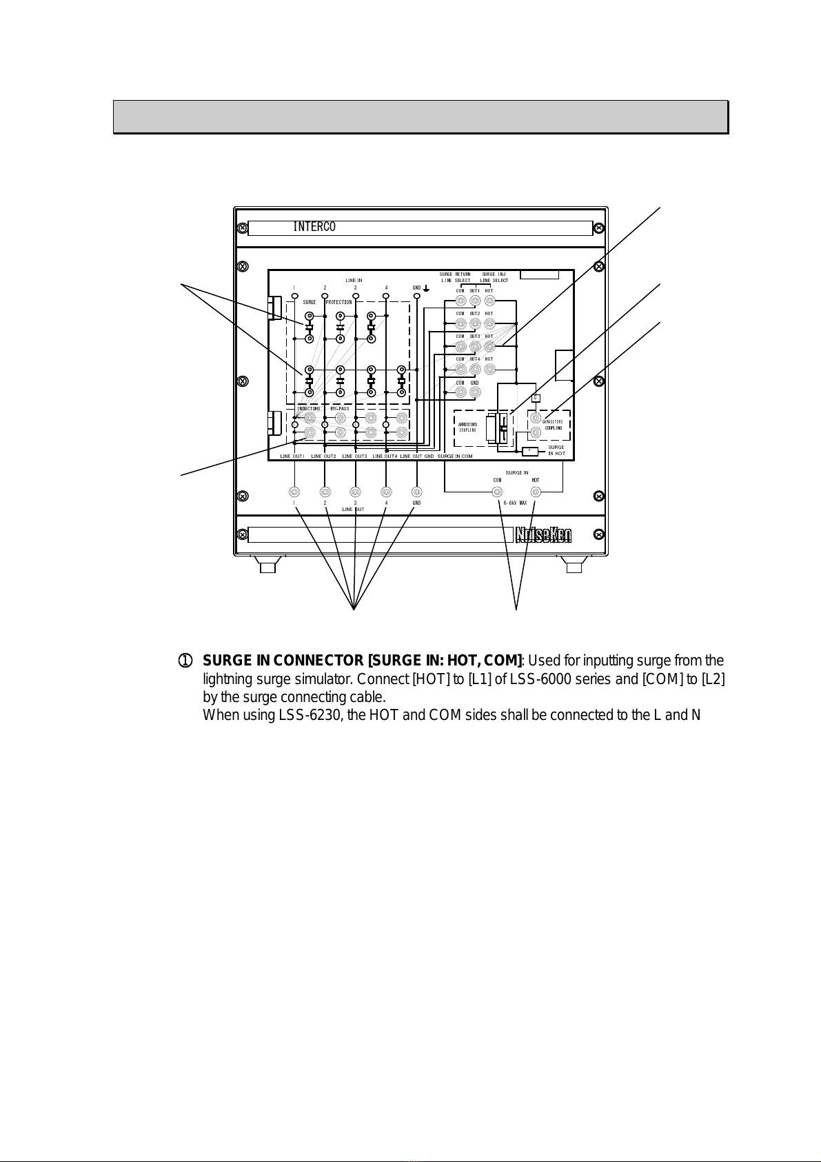
6.APPEARANCE OF THE UNIT
FRONT PANEL
1 2 3 4 GND
INTERCONECTION LINE UNIT LSS-INJ6400SIG
COM HOT
6.6kV MAX
C
L L L L
1 2 3 4 GND
INDUCTORS BY-PASS
SURGE PROTECTION
R
COM
COM
COM
COM
COM
OUT1
OUT2
OUT3
OUT4
GND
HOT
HOT
HOT
HOT
SURGE RETURN SURGE INJ
LINE SELECT
ARRESTORS
COUPLING
CAPACITORS
COUPLING
LINE SELECT
LINE IN
LINE OUT1 LINE OUT2 LINE OUT3 LINE OUT4 LINE OUT GND SURGE IN COM
LINE OUT
SURGE IN
SURGE
IN HOT
①⑦
③
②
④
⑤
⑥
①
①①
①
SURGEINCONNECTOR[SURGEIN:HOT,COM]:Usedforinputtingsurge fromthe
lightning surge simulator. Connect [HOT] to [L1] of LSS-6000 series and [COM] to [L2]
bythe surgeconnectingcable.
WhenusingLSS-6230,theHOTandCOMsidesshallbeconnectedtotheLandN
②
②②
②
sidesof EUTLINEOUTPUTterminals,respectively,byusingthesupplied
③
③③
③
Surge INCable (forLSS-6230)
④
④④
④
ARRESTORS COUPLING PART [ARRESTORS COUPLING]: Connects the
capacitor /arrestorunitorthearrestorunit(accessory)incaseofarrestorcouplingtest.
⑤
⑤⑤
⑤
CAPACITORS COUPLING PART [CAPACITORS COUPLING]: Connects the
connectionplug(accessory)incaseofcapacitorcouplingtest.
⑥
⑥⑥
⑥
SURGE INJECTION SETTING PART [SURGE INJ LINE SELECT] [SURGE
RETURNLINESELECT]:Selectssurgeinjectionlineandreturnline.
⑦
⑦⑦
⑦
SURGE PROTECTION INSTRUMENT CONNECTOR [SURGE PROTECTION]:
Used for connecting surge protection instruments to avoid surge return. A gas arrestor
(90V) is connected when shipped. Remove the gas arrestor or connect other surge
protectioninstrumentsdependingoncases.
⑧
⑧⑧
⑧
INDUCTOR BY-PASS CONNECTOR [INDUCTORS BY-PASS]: Connects the
connection plug in case of bypassing inductors in the decoupling network. In case of
bypassinginductors,neverfailtobypassalllines.
⑨
⑨⑨
⑨
DC LINE OUT CONNECTOR [LINE OUT: 1,2,3,4,GND]: Supplies power to EUT and
injectssurgetolinessetbysurgeinjectionsetpart.
10
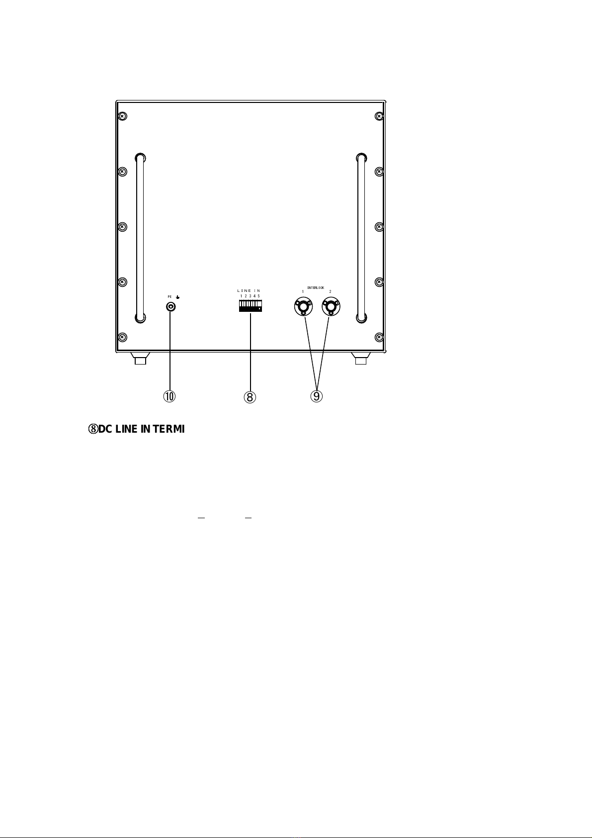
REAR PANEL
1 2 3 4
PE
INTERLOCK
1 2
5
LINE IN
⑧
⑩ ⑨
⑧
⑧⑧
⑧DCLINEINTERMINAL [LINEIN]:InputspowerforEUT.
⑨
⑨⑨
⑨INTERLOCK CONNECTOR [INTERLOCK: 1,2]: Connect [1] to the lightening surge
simulator’s interlock connector by the interlock connection cable (accessory). Connect
interlockconnector(ofthesurgesimulator’saccessory)to[2].
⑩
⑩⑩
⑩PE TERMINAL [PE]: Protective Earth terminal of the unit. Never fail to connect [PE] to FG
terminalofthelighteningsurgesimulator(LSS-6000series)byPEcable(accessory).
11
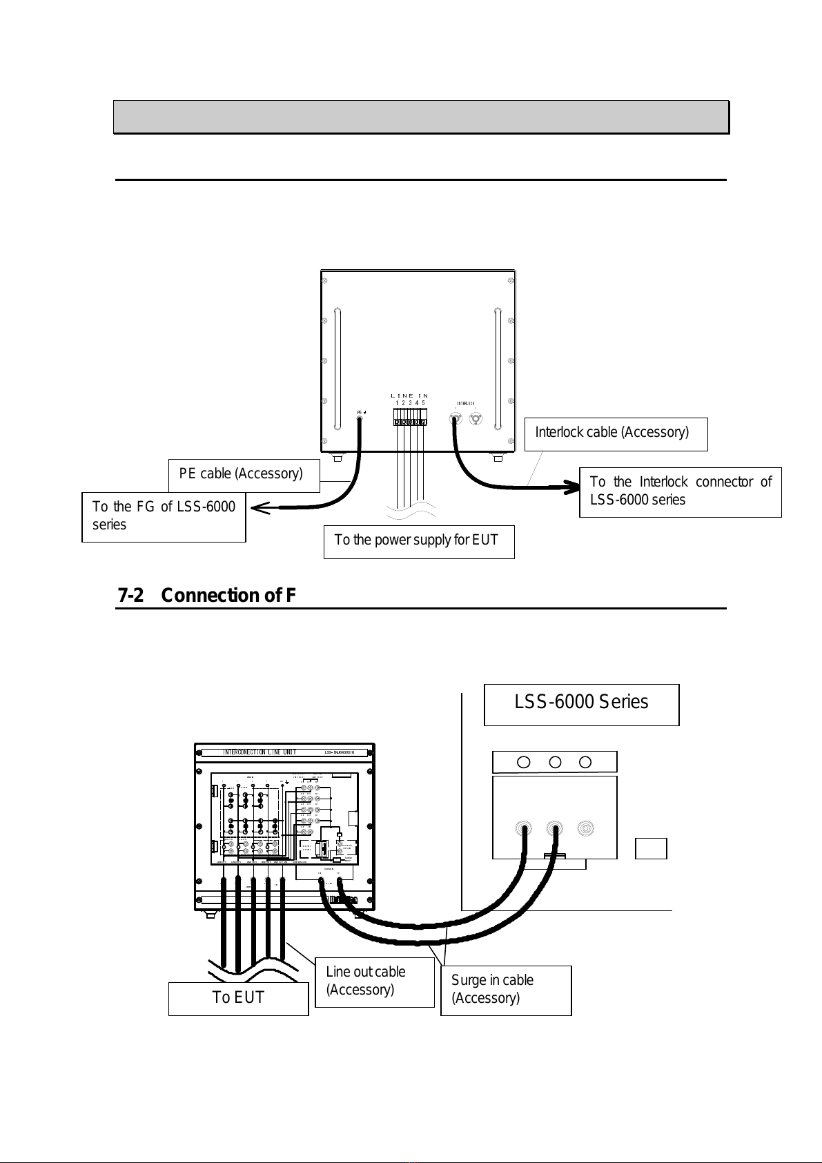
7. HOW TO CONNECT EQUIPMENT
7-1
Connection of Rear Panel
Connect PE terminal to FG terminal of LSS-6000 series by PE cable (accessory) as indicating in the
figure below. Connect the interlock connector [1] to the LSS-6000 series interlock connector by the
interlock cable (accessory). As not attached, prepare cable to Line In terminal (material:
AGW10-24).
1 2 3 4
PE
INTERLOCK
1 2
5
LINE IN
EUT供給電源へ
(添付品)
インターロックケーブル
LSS-6000シリーズ
インターロックコネクタへ
FG端子へ
P ケーブル
(添付品)
LSS-6000シリーズ
7-2
Connection of Front Panel (in case of LSS-6000 Series)
Connect the surge in connector [SURGE IN: HOT, COM] to the surge out terminal [L1, L2]
by the surge in cable (accessory). Connect line out connecter [LINE OUT: 1,2,3,4,GND] to
EUT by DC line cable.
L1 L2 PE
LSS-6000シリーズ
LINE ON
EUT(供試体)へ
サージ入力ケーブル
(添付品)
1 2 3 4 GND
INTERCONECTION LINE UNIT
LSS-INJ6400SIG
COM HOT
6kV MAX
C
L L L L
1 2 3 4 GND
INDUCTORS BY-PASS
SURGE PROTECTION
R
COM
COM
COM
COM
COM
OUT1
OUT2
OUT3
OUT4
GND
HOT
HOT
HOT
HOT
SURGE RETURN SURGE INJ
LINE SELECT
ARRESTORS
COUPLING
CAPACITORS
COUPLING
LINE SELECT
LINE IN
LINE OUT1 LINE OUT2 LINE OUT3 LINE OUT4 LINE OUT GND SURGE IN COM
LINE OUT
SURGE IN
SURGE
IN HOT
ライン出力ケーブル
(添付品)
To the FG of LSS-6000
series
PEcable(Accessory)
TothepowersupplyforEUT
Interlockcable(Accessory)
To the Interlock connector of
LSS-6000series
LSS-6000Series
ToEUT
Line outcable
(Accessory)
Surgeincable
(Accessory)
12
7-3
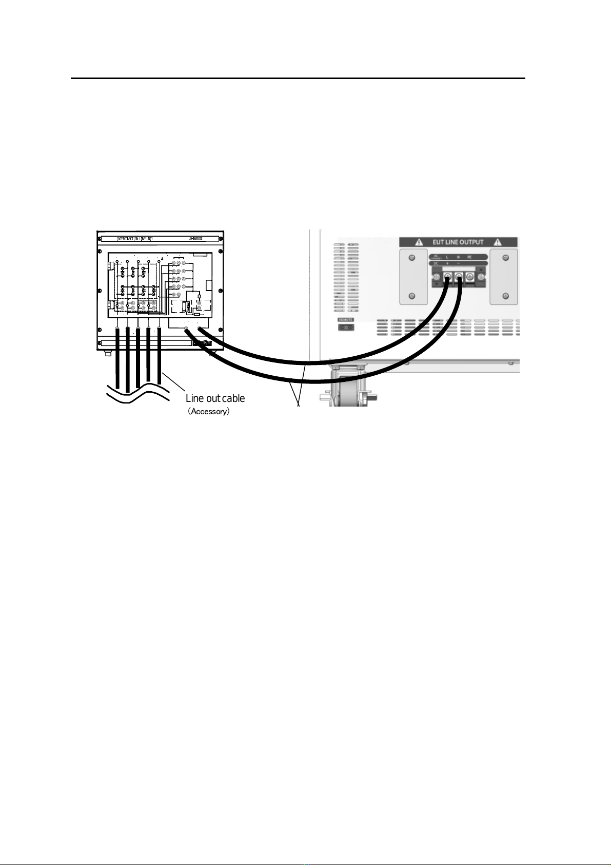
Connection of the front panel (in case of LSS-6230)
ConnectionoftheLSS-INJ6400SIGtotheLSS-6230isdonebyusingthe
suppliedSurgeInCable.Connectthesafetysocketsideofthecablestothe
SURGEINterminalsontheLSS-INJ6400SIGandsolderlessterminalsidetothe
EUTLINEOUPTUT(L,N)terminalsontheLSS-6230.
Next, connect the safety socket side of the supplied Line Out Cables to the
LINE OUT terminals (LINE OUT , 2, 3, 4, GND). Connect the EUT to the other
end of the cables (clip side)
Surge in cable (Accessory)
To
EUT
1
2
3
4
GND
INTERCONECTION LINE UNIT
LSS-
INJ6400SIG
COM
HOT
6kV MAX
C
L
L
L
L
1
2
3
4
GND
INDUCTORS
BY
-
PASS
SURGE
PROTECTION
R
COM
COM
COM
COM
COM
OUT1
OUT2
OUT3
OUT4
GND
HOT
HOT
HOT
HOT
SURGE RETURN
SURGE I
NJ
LINE SELECT
ARRESTORS
COUPLING
CAPACITORS
COUPLING
LINE SELECT
LINE IN
LINE OUT1
LINE OUT2
LINE OUT3
LINE OUT4
LINE OUT GND
SURGE IN COM
LINE OUT
SURGE IN
SURGE
IN HOT
Lineoutcable
(Accessory)
13
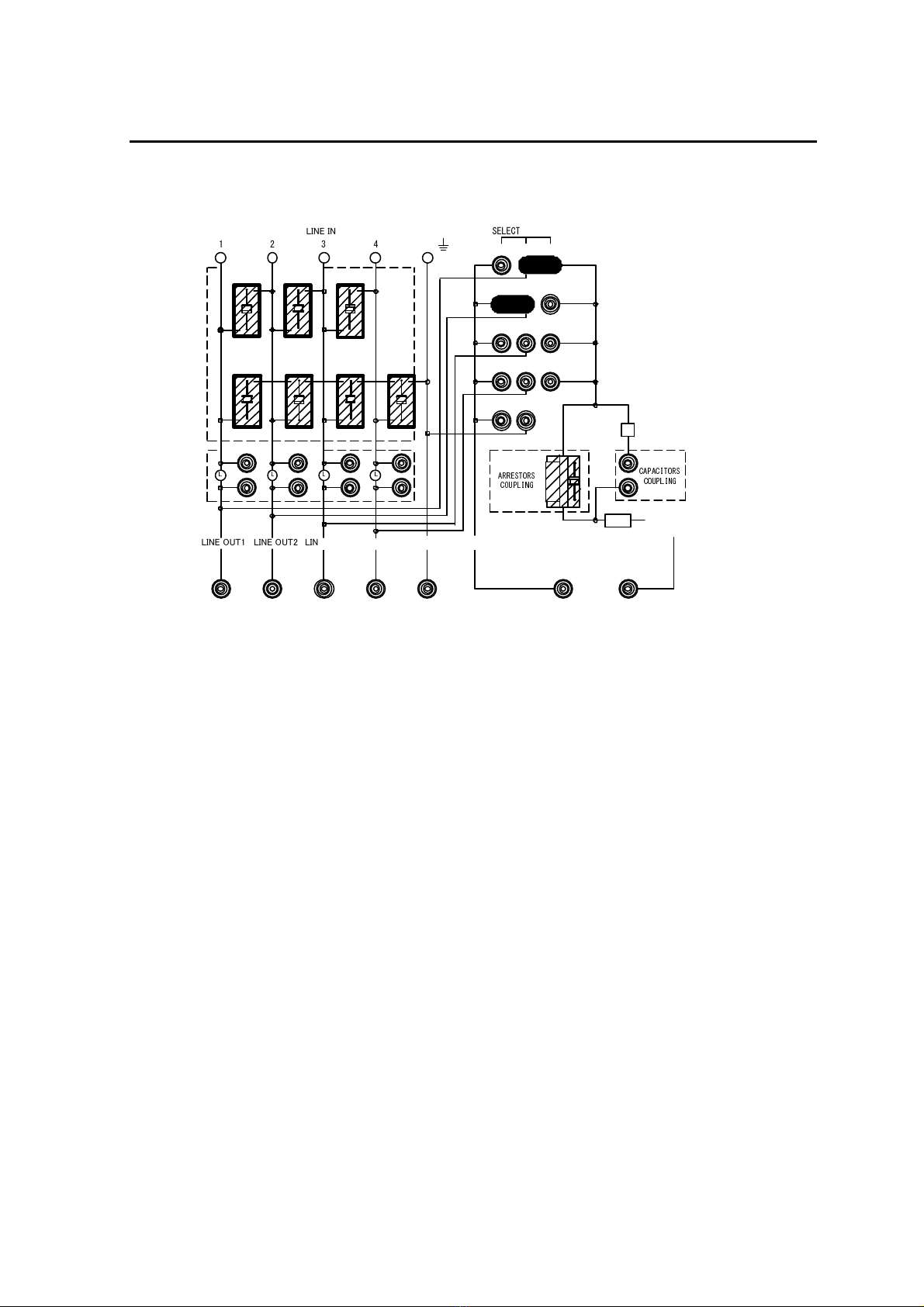
7-3
Setting When Arrestors Coupling
(1)ToinjectsurgetoLine-Line
Example: In case of injection line: [OUT1] and return line: [OUT2]
1 2 3 4 GND
COM HOT
C
L L L L
1 2 3 4 GND
INDUCTORS BY-PASS
SURGE PROTECTION
R
COM
COM
COM
COM
COM
OUT1
OUT2
OUT3
OUT4
GND
HOT
HOT
HOT
HOT
SURGE RETURN SURGE INJ
LINE SELECT
ARRESTORS
COUPLING
CAPACITORS
COUPLING
LINE SELECTLINE IN
LINE OUT1 LINE OUT2 LINE OUT3 LINE OUT4 LINE OUT GND SURGE IN COM
LINE OUT
SURGE IN
SURGE
IN HOT
6.6kV MAX
①
Connect the capacitor / arrestor unit (accessory) or the arrestor unit (accessory) to
[ARRESTORSCOUPLING].
*Use the capacitor / arrestor unit if transmission signal of EUT is less than 5kHz, and use
thearrestorunitifmorethan5kHz.
②
Connect the connection plug to [SURGE INJ LINE SELECT] [SURGE RETURN LINE
SELECT]. The above figure shows the example of setting [OUT1] as the surge injection
lineand[OUT2]asthesurgereturnline.
③
The gas arrestor (90V) is connected to [SURGE PROTECTION]. Remove the gas
arrestororconnectinganothersurgeprotectioninstrumentdependingonnecessity.
*The gas arrestor is connected when shipped. The gas arrestor should be changed if it
does not emit light when surge injected. In case of using surge absorbers etc other than
thegas arrestor,connectasurgeprotectioninstrumentdependingon testconditions.
④
In case of bypassing the inductor (20mH) in the decoupling network, connect the
connectionplug(accessory)to[INDUTORSBY-PASS].Neverfailtobypassalllines.
*In case of bypassing the inductor (20mH), the surge may return to the line input side and
damageEUT.Besides,thesurgemaynotinjecttoEUT.
14
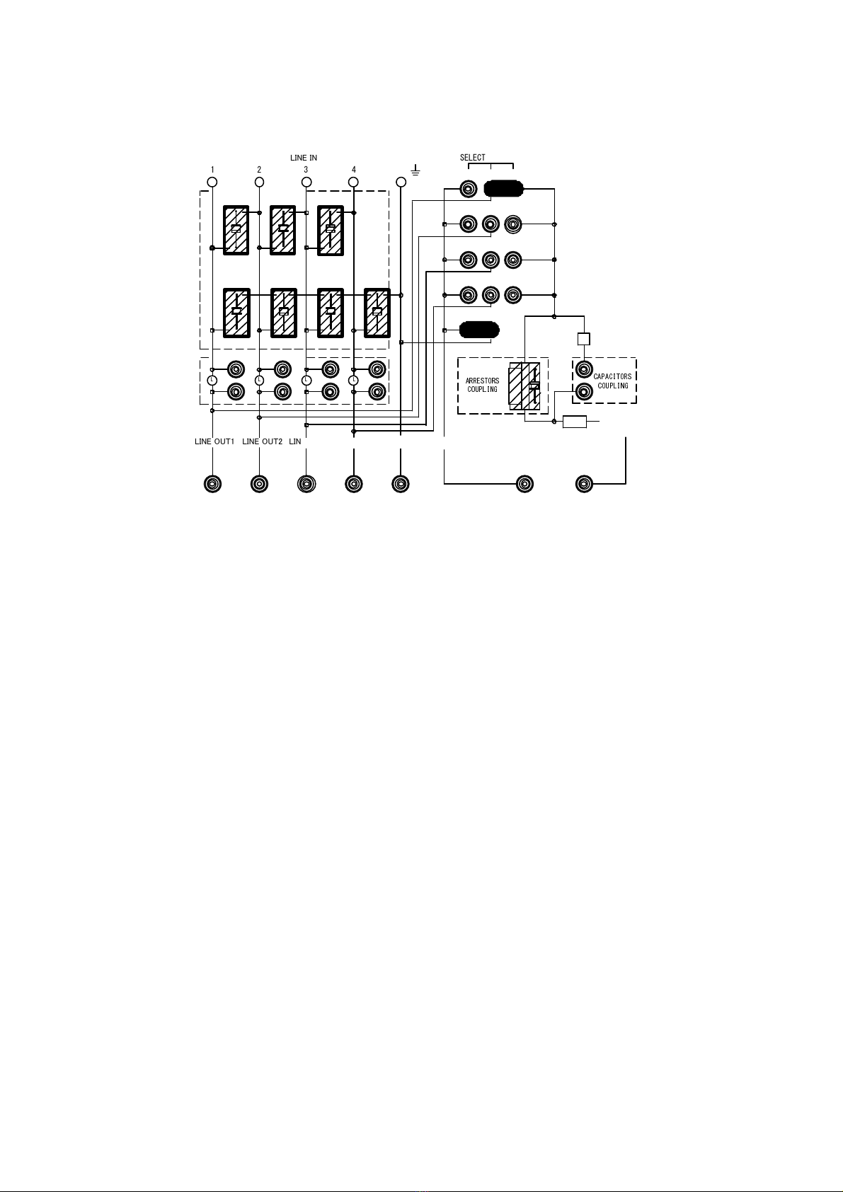
(2) To inject surge to Line-Ground
Example: In case of injection line: [OUT1] and return line: [GND].
1 2 3 4 GND
COM HOT
C
L L L L
1 2 3 4 GND
INDUCTORS BY-PASS
SURGE PROTECTION
R
COM
COM
COM
COM
COM
OUT1
OUT2
OUT3
OUT4
GND
HOT
HOT
HOT
HOT
SURGE RETURN SURGE INJ
LINE SELECT
ARRESTORS
COUPLING
CAPACITORS
COUPLING
LINE SELECTLINE IN
LINE OUT1 LINE OUT2 LINE OUT3 LINE OUT4 LINE OUT GND SURGE IN COM
LINE OUT
SURGE IN
SURGE
IN HOT
6.6kV MAX
① Connect the capacitor / arrestor unit (accessory) or the arrestor unit (accessory) to
[ARRESTORSCOUPLING].
*Use the capacitor / arrestor unit if transmission signal of EUT is less than 5kHz, and use
thearrestorunitifmorethan5kHz.
② Connect the connection plug to [SURGE INJ LINE SELECT] [SURGE RETURN LINE
SELECT]. The above figure shows the example of setting [OUT1] as the surge injection
lineand[GND]asthesurge returnline.
③ The gas arrestor (90V) is connected to [SURGE PROTECTION]. Remove the gas
arrestororconnectinganothersurgeprotectioninstrumentdependingonnecessity.
*The gas arrestor is connected when shipped. The gas arrestor should be changed if it
does not emit light when surge injected. In case of using surge absorbers etc other than
thegas arrestor,connectasurgeprotectioninstrumentdependingon testconditions.
④ In case of bypassing the inductor (20mH) in the decoupling network, connect the
connectionplug(accessory)to[INDUTORSBY-PASS].Neverfailtobypassalllines.
*In case of bypassing the inductor (20mH), the surge may return to the line input side and
damageEUT.Besides,thesurgemaynotinjecttoEUT.
15
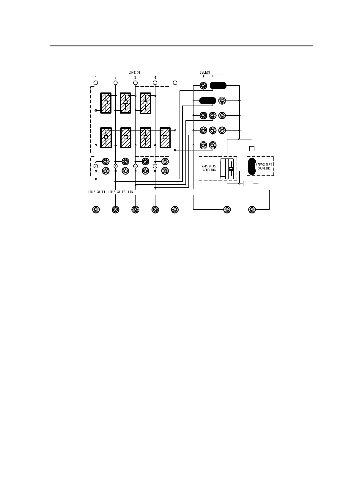
7-4 Setting When Capacitors Coupling
(1)ToinjectsurgetoLine-Line
Example: In case of injection line: [OUT1] and return line: [OUT2]
1 2 3 4 GND
COM HOT
6.6kV MAX
C
L L L L
1 2 3 4 GND
INDUCTORS BY-PASS
SURGE PROTECTION
R
COM
COM
COM
COM
COM
OUT1
OUT2
OUT3
OUT4
GND
HOT
HOT
HOT
HOT
SURGE RETURN SURGE INJ
LINE SELECT
ARRESTORS
COUPLING
CAPACITORS
COUPLING
LINE SELECTLINE IN
LINE OUT1 LINE OUT2 LINE OUT3 LINE OUT4 LINE OUT GND SURGE IN COM
LINE OUT
SURGE IN
SURGE
IN HOT
① Connect the connection plug (accessory) to
[CAPACITORSCOUPLING].
②
Connect the connection plug to [SURGE INJ LINE SELECT] [SURGE RETURN LINE
SELECT]. The above figure shows the example of setting [OUT1] as the surge injection
lineand[OUT2]asthesurgereturnline.
③
The gas arrestor (90V) is connected to [SURGE PROTECTION]. Remove the gas
arrestororconnectinganothersurgeprotectioninstrumentdependingonnecessity.
*The gas arrestor is connected when shipped. The gas arrestor should be changed if it
does not emit light when surge injected. In case of using surge absorbers etc other than
thegas arrestor,connectasurgeprotectioninstrumentdependingon testconditions.
④
In case of bypassing the inductor (20mH) in the decoupling network, connect the
connectionplug(accessory)to[INDUTORSBY-PASS].Neverfailtobypassalllines.
*In case of bypassing the inductor (20mH), the surge may return to the line input side and
damageEUT.Besides,thesurgemaynotinjecttoEUT.

16
(2) To inject surge to Line-Ground
Example: In case of injection line: [OUT1] and return line: [GND].
1 2 3 4 GND
COM HOT
C
L L L L
1 2 3 4 GND
INDUCTORS BY-PASS
SURGE PROTECTION
R
COM
COM
COM
COM
COM
OUT1
OUT2
OUT3
OUT4
GND
HOT
HOT
HOT
HOT
SURGE RETURN SURGE INJ
LINE SELECT
ARRESTORS
COUPLING
CAPACITORS
COUPLING
LINE SELECTLINE IN
LINE OUT1 LINE OUT2 LINE OUT3 LINE OUT4 LINE OUT GND SURGE IN COM
LINE OUT
SURGE IN
SURGE
IN HOT
6.6kV MAX
① Connect the connection plug (accessory) to
[CAPACITORSCOUPLING].
②
Connect the connection plug to [SURGE INJ LINE SELECT] [SURGE RETURN LINE
SELECT]. The above figure shows the example of setting [OUT1] as the surge injection
lineand[GND]asthesurge returnline.
③
The gas arrestor (90V) is connected to [SURGE PROTECTION]. Remove the gas
arrestororconnectinganothersurgeprotectioninstrumentdependingonnecessity.
*The gas arrestor is connected when shipped. The gas arrestor should be changed if it
does not emit light when surge injected. In case of using surge absorbers etc other than
thegas arrestor,connectasurgeprotectioninstrumentdependingon testconditions.
④ In case of bypassing the inductor (20mH) in the decoupling network, connect the
connectionplug(accessory)to[INDUTORSBY-PASS].Neverfailtobypassalllines.
*In case of bypassing the inductor (20mH), the surge may return to the line input side and
damageEUT.Besides,thesurgemaynotinjecttoEUT.
When using the unit, never fail to turn off the line switch of LSS-6000 series.
If AC or DC power is supplied to [HOT] and [COM] terminals of the unit from
LSS-6000 series, the unit may cause combustion.
17
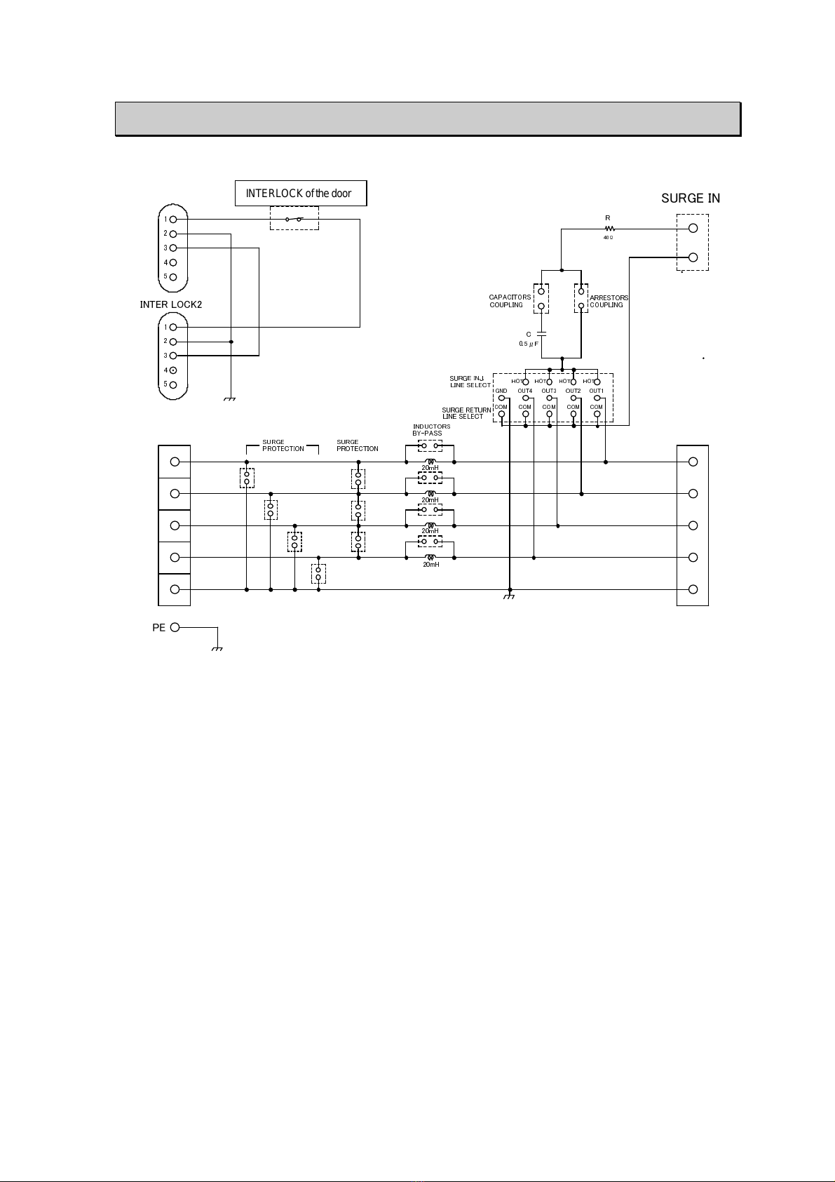
8. BLOCK CHART
HOT
COM
INTER LOCK1
LINE IN (DC50V/1A)
1
2
3
4
G
LINE OUT
OUT1
OUT2
OUT3
OUT4
GND
1
2
3
4
5
1
2
3
4
5
アクリル扉部インターロックスイッチ
40Ω
0.5μF
C
SURGE INJ.
LINE SELECT
SURGE RETURN
LINE SELECT
HOT
PE
20mH
20mH
20mH
INTER LOCK2
BY-PASS
INDUCTORS
SURGE IN
PROTECTION
SURGE PROTECTION
SURGE
20mH
HOT HOT HOT
OUT1OUT2OUT3OUT4GND
COM COM COM COM COM
R
ARRESTORS
COUPLINGCOUPLING
CAPACITORS
INTERLOCKofthedoor
This manual suits for next models
1
Table of contents
Other NoiseKen Test Equipment manuals

NoiseKen
NoiseKen ESS-S3011 User manual

NoiseKen
NoiseKen INS-AX2 Series User manual

NoiseKen
NoiseKen FNS-AX4-A20-N2447 User manual

NoiseKen
NoiseKen GT-30R User manual

NoiseKen
NoiseKen 03-00074A User manual

NoiseKen
NoiseKen LSS-F03 Series User manual

NoiseKen
NoiseKen LSS-F02 Series User manual

NoiseKen
NoiseKen ESS-801 User manual

NoiseKen
NoiseKen LSS-720B2 User manual

NoiseKen
NoiseKen 01-00006A User manual


