Training and Vendor Development
CMO Operations & Logistics
Multimedia Creation & Support CONFIDENTIAL 12.Sept.2007
3
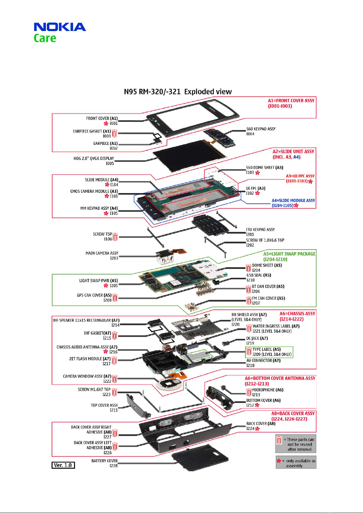
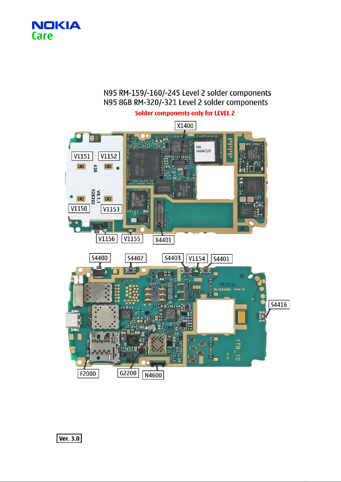
Service Manual N95 RM-159/-245/-160/RM320/-321 Copyright © 2007 NOKIA Corporation. All rights reserved.
Approved 6.0
MGR
Page (53)
The purpose of this document is to help NOKIA service levels 1 and 2 workshop technicians to carry out service to
NOKIA products. This Service Manual is to be used only by authorized NOKIA service suppliers, and the content of it is
confidential. Please note that NOKIA provides also other guidance documents (e.g. Service Bulletins) for service sup-
pliers, follow these regularly and comply with the given instructions.
While every endeavor has been made to ensure the accuracy of this document, some errors may exist.
If you find any errors or if you have further suggestions, please notify NOKIA using the address below:
Please keep in mind also that this documentation is continuously being updated and modified, so watch always out
for the newest version.
Warnings and Cautions
Please refer to the phone’s user guide for instructions relating to operation, care and maintenance including impor-
tant safety information. Note also the following:
Warnings:
CARE MUST BE TAKEN ON INSTALLATION IN VEHICLES FITTED WITH ELECTRONIC ENGINE MANAGEMENT SYSTEMS
AND ANTI–SKID BRAKING SYSTEMS. UNDER CERTAIN FAULT CONDITIONS, EMITTED RF ENERGY CAN AFFECT THEIR
OPERATION. IF NECESSARY, CONSULT THE VEHICLE DEALER/MANUFACTURER TO DETERMINE THE IMMUNITY OF VEHI-
CLE ELECTRONIC SYSTEMS TO RF ENERGY.
THE HANDPORTABLE TELEPHONE MUST NOT BE OPERATED IN AREAS LIKELY TO CONTAIN POTENTIALLY EXPLOSIVE
ATMOSPHERES, EG PETROL STATIONS (SERVICE STATIONS), BLASTING AREAS ETC.
OPERATION OF ANY RADIO TRANSMITTING EQUIPMENT, INCLUDING CELLULAR TELEPHONES, MAY INTERFERE WITH
THE FUNCTIONALITY OF INADEQUATELY PROTECTED MEDICAL DEVICES. CONSULT A PHYSICIAN OR THE MANUFACTUR-
ER OF THE MEDICAL DEVICE IF YOU HAVE ANY QUESTIONS. OTHER ELECTRONIC EQUIPMENT MAY ALSO BE SUBJECT TO
INTERFERENCE.
Cautions:
1. Servicing and alignment must be undertaken by qualified personnel only.
2. Ensure all work is carried out at an anti–static workstation and that an anti–static wrist strap is worn.
3. Use only approved components as specified in the parts list.
4. Ensure all components, modules screws and insulators are correctly re–fitted after servicing and alignment.
5. Ensure all cables and wires are repositioned correctly.
1.
2.
3.
Electrostatic discharge can easily damage the sensitive components of electronic products.
Therefore every Service Supplier has to take care of all precautions, which are mentioned in the
service level related “Service Partner Requirements”, available on NOKIA Online. Also see ESD
Protection Requirements in this Service Manual.
INTRODUCTION1.