6505
Gayhart
St.,
Commerce,
CA
90040
|
Phone:
800.686.6672
|
www.noralighting.com
|
e-mail:
[email protected] Instructions subject to change without notice. © 2018 100218P2
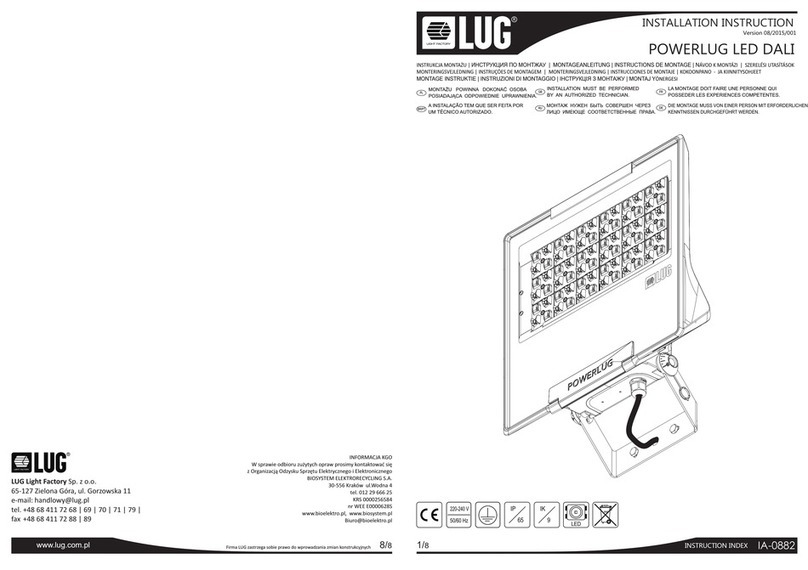
Installation Instructions
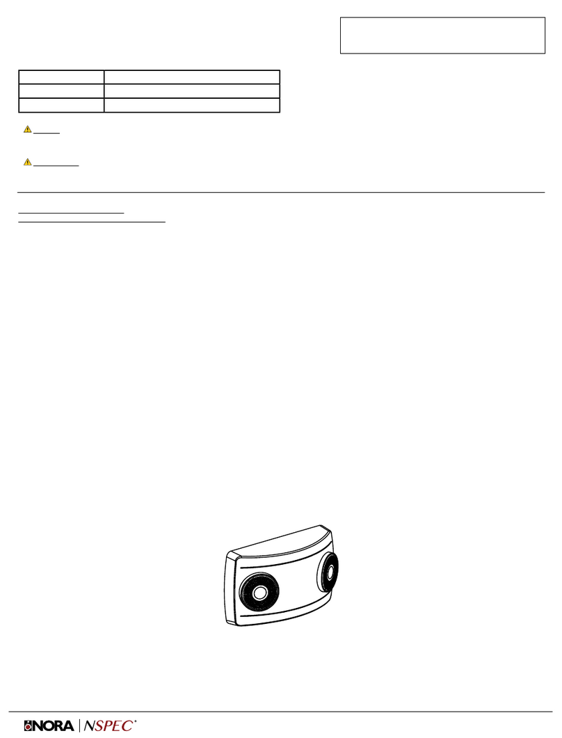
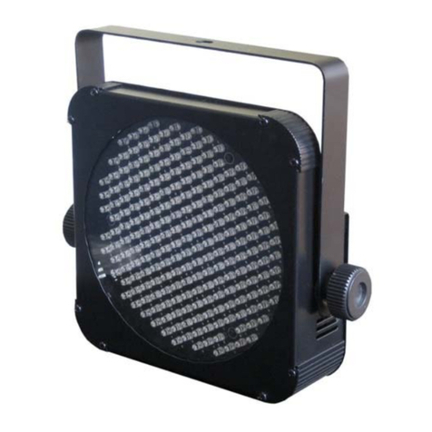
NE-602LEDHORC - Compact Size LED Emergency Light, High Output
READ PRIOR TO ATTEMPTING INSTALLATION
ALWAYS TURN OFF MAIN POWER BEFORE INSTALLATION
INSTALLATION SHOULD BE CARRIED OUT BY YOUR LOCAL ELECTRICIAN
Only narrow lens have an adjustable function.
Adjust the lamp head and lens direction
according to the direction needed.
Figure 1
Figure 2
Figure 3
Figure 4
Figure 5
Open Fixture
Wall mount - Back Power Feed
Ceiling mount - Top Power Feed
Wall mount - Top Power Feed
Adjusting the lamp head and lens
WALL MOUNT - BACk POWER FEED (FIGURE 2)
1. Use flat blade screwdriver. Insert the screwdriver to the slots and pry off front
cover from fixture. (Figure 1)
2. Remove the appropriate knock out from back plate and mount the back plate to the J-Box.
3. Remove the knockout located in the center of the back plate and feed the wires through the hole.
4. Secure the backplate to the J-Box
5. Connect the J-Box wires to the power supply wires using the wire nuts provided.
Connect the white wire to neutral.
If using 120V, connect the black wire to the hot lead.
If using 227V, connect the orange wire to the hot lead.
Cap the unused lead and press the wires into the J-Box. (Refer to the wiring diagram below)
6. Connect remote heads. Refer to the instruction for remote heads.
7. Connect the battery connector. (Figure 2)
8. Snap the front cover onto the back plate.
9. Restore power and press the test button and wait for the LED heads to turn on.
10. Adjust the lamp head and lens direction as needed. (Figure 5)
CEILING MOUNT - TOP POWER FEED (FIGURE 3)
Refer to the instructions above, (Wall mount - Back Power Feed)
Difference between Back power feed and Top power feed:
1. Mount the back plate on the ceiling surface instead of the wall surface.
2. Feed the building AC supply wire through the back plate then connect to the fixture power supply
using the wire nuts provided.
CONNECTING REMOTE HEADS (FIGURE 2)
1. Attach the remote wire onto the remote connector on the PCBA.
2. Connect the remote head’s extended wire to the remote wire.
Yellow = Positive (+)
Purple = Negative (-)
3. Connect the wires using the wire nuts provided.
WALL MOUNT - SURFACE WIRING (TOP POWER FEED) (FIGURE 4)
1. Open the front cover and remove the top knockout on the top flange of the fixture.
2. Secure the conduit (or the surface raceway) to the knockout and feed the wires.
3. Remove the keyhole knockout on the back plate and mount to the wall.
4. Refer to steps 5-10 in the Wall Mount - Back Power Feed instructions.
Wiring Diagram
Remote capability reference:
NE-602LEDHORC has max. 3.6V 2W remote capabilities
NE-602LEDRC has max 3.6V 4W remote capabilities.


