13
IMPORTANT:
Provide enough slack in the sensor branch cable (C2) to account for the
movement of the main section, parallel lift, and FOLDING boom
movement.
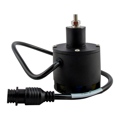
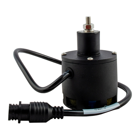
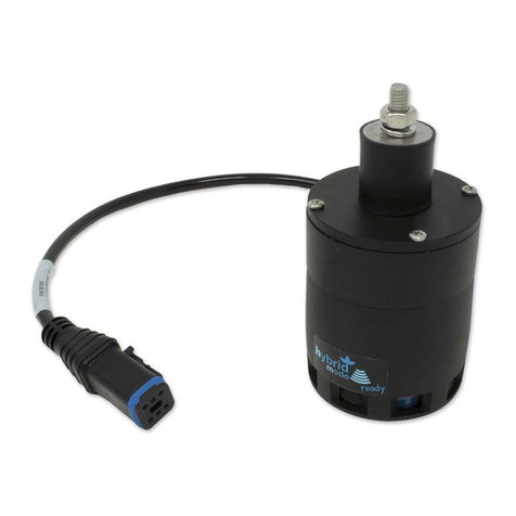
3. Mount one NORAC ultrasonic sensor (Item E2) near the tip of each boom with
the brackets provided (Item B19). Using the 8-mm nuts and lock washers
provided with the sensor to attach the sensor to the bracket. The sensors should
be oriented forward (ahead) of the boom.
General mounting rules for ultrasonic wing sensors:
•When the boom is in its lowest position, the sensor mouth must be 9 inches or
more from the ground.
•The bottom of the sensor must be at least 9 inches in front of the spray
nozzles.
•The bottom of the sensor must be at least 9 inches above the spray nozzles.
•The sensor should be approximately vertical at normal operating heights.
•Ensure that there are no obstructions within a 12-inch diameter circle
projected directly below the center of the sensor.
Improved boom tip protection and control may be obtained by mounting the
sensor as close to the end of the boom as possible. However, if the sensors
are mounted to the breakaway portion of the boom, the operator must
be aware that, due to boom geometry, a breakaway action may cause
the UC4 controller to force the boom dangerously close to the ground.
Because of this, you may want to avoid mounting on a breakaway
section.
Please refer to the UC4 system warranty at the end of the UC4 Sprayer Boom
Control Operator’s Manual (Item M1) for implications.
NOTE: When installing the UC4 sensors (Items E2), start with the
smallest serial number on the left hand side proceeding to the
largest serial number on the right hand side (Figure 5). This will
allow for a more intuitive setup when tuning the system. This
arrangement is also REQUIRED when using the “QUICK
SETUP” feature available via the UC4 Control Panel software
(this feature is typically used by NORAC technical support staff).


