Norcross DEPTHTRAX DT1B Guide

www.hawkeyeelectronics.com
To ensure safety and many years of trouble-free operation of your product,
please read this manual carefully before using this product.
SAFETY INFORMATION:
•Periodically wipe the face with a dry cloth. Do not use abrasives or
solvents on this device.
•Only qualified personnel should perform repairs or servicing not covered
in this manual.
•The LCD used in the product is made of glass. Therefore, it can break
when the product is dropped or impacted.
•Keep this product away from heat sources such as radiators, heaters,
stoves and other heat generating sources. Do not store in extreme
temperatures above 150° F (65° C).
•Shade the LCD during storage. Do not expose LCD to direct sunlight for
extended periods of time. Use the supplied cover at all times during
storage.
NOTES, NOTICES, AND CAUTIONS
WARNING: Indicates a potential for property damage, personal injury or
death.
IMPORTANT: Indicates potential damage to the device and tells you how to
avoid it.
NOTICE: Indicates important information that helps you make better use of
the device and tells you how to correct a performance problem.
INFORMATION: Indicates resources to obtain the proper information to help
you make the most of your device.
INFORMATION:
Read this manual completely before attempting to use or
install your device. Visit our Customer Service Center on our
website for advanced troubleshooting and technical support.
W
ARNING
:
This depth sounder should not be used as a navigational aid
to prevent grounding, boat damage, or personal injury. Always
operate the boat at slow speeds in unfamiliar water, or if you
suspect shallow water or submerged objects.
DEPTHTRAX
®
TRANSOM/GLUE IN TRANSDUCER
INSTALLATION AND ADJUSTMENT INSTRUCTIONS

www.hawkeyeelectronics.com
PARTS SUPPLIED IN PACKAGING
The following parts should be included with the transducer:
•Transom/Glue-In Transducer with 30 ft Cable and Plug
•Transducer Support Bracket with Attached Kick-Up Bracket
•(2) Tapered Plastic Shims
•(2) Cable clamps
•Clam Shell Cable Cover
•(2) #10 x 1.25” self-tapping screws
•(4) #6 x 1/2” self-tapping screws
If any items are missing or damaged, please contact our customer service
department.
SELECTING THE PROPER TRANSDUCER INSTALLATION
N
OTICE
:
The included transducer can be either Transom
Mounted or Glued In-Hull. We also offer the option
to trade-in the standard transducer for a customized
transducer. Please visit our website for details.
Transom mounting is suitable for the following vessels:
•Outboard, inboard/outboard, single inboard or jet-drive propulsion.
•Hull deadrise angle below 30°.
•Transom angle from 3-20°.
Glue-in mounting is suitable for the following vessels:
•High speed boats to increase the performance of the depth sounder.
•Trailer boats to prevent accidental damage to the transducer from
trailering.
•Shallow draft boats to prevent accidental damage to the transducer from
intentional or unintentional ground.
•NON-CORED hulls or aluminum hulls thinner than 1/8”.
•Inboard vessels that have a lot of running gear that creates significant
turbulence.

www.hawkeyeelectronics.com
N
OTICE
:
Glue-in mounting of the transducer is NOT suitable for all
vessels. You MUST test the glue-in location on the water prior
to using epoxy to permanently affix it to the hull. If you cannot
obtain satisfactory readings during on water testing you will need to
transom mount the transducer, or switch to a customer transducer.
If you think that the included transducer is not suitable for your installation, return
to the place of purchase and exchange it for the correct transducer. You can
also visit our Customer Service Center at www.hawkeyelectronics.com to contact
us or to complete a transducer exchange request to exchange the transducer for
one that is specialized for your vessel. You may also email us at
support.norcrossmarine.com to inquire about exchanging the transducer.
TRANSOM MOUNTING THE TRANSDUCER
I
MPORTANT
:
Transom mounting the transducer is suitable for most
vessels and generally offers the best performance. If you
decide to glue the transducer in-hull, you MUST test the
location on water prior to permanently affixing it to the hull.
If you cannot obtain satisfactory readings during on water testing you
will need to transom mount the transducer, or switch to a custom
transducer. If you have determined that you are going to try to glue
the transducer in-hull, please skip to the next section.
Tools & Supplies Required for Installation
•Power Drill
•5/8” (16 mm) drill bit, hole saw or spade bit
•1/8” (3 mm) drill bit
•9/64” (4 mm) drill bit
•Marine Sealant/Caulk
•30 Grit Sandpaper
•“Phillips” Screwdriver
•Pencil
•Tie Wraps
•Water Based Antifouling Paint
•Masking Tape

www.hawkeyeelectronics.com
Transom mounting is suitable for the following vessels:
•Outboard, inboard/outboard, single inboard, or jet-drive propulsion.
•Hull deadrise angle below 30°.
•Transom angle from 3-20°.
N
OTICE
:
To get a good “view” of the mounting location, while the
vessel is out of the water, position yourself at the transom
and look at the bottom of the hull towards the bow. Using
illustrations A thru I, note anything that could interrupt the clean flow
of water to the transducer mounting location.
N
OTICE
:
To achieve maximum performance try the following:
Have someone run the boat on plane for you in smooth
water. CAREFULLY look over the transom at the water
flowing from the bottom of the boat. Find the location which produces
the least amount of turbulence (air bubbles). This is the location you
will want to mount the transducer.
N
OTICE
:
To prevent drilling holes too deeply, wrap
masking tape around the bit 7/8" (22
mm) from the point. To minimize surface
cracking on
fiberglass hulls use a
chamfer or countersink bit. If either is not
available, start drilling with a 1/4" (6 mm)
bit to a depth of 1/16" (1 mm), then finish
the hole with the 9/64" (4mm) bit.

www.hawkeyeelectronics.com
STEP 1
Choosing a Mounting Location
To obtain the best performance, the transducer
should be mounted in a location where the water
flow beneath the hull is aeration and turbulence-free.
Try to mount the transducer as close to the
centerline of the boat as possible. Consult the boat
manufacturer for the best in-hull transducer
placement. If this information is unavailable, follow
the guidelines below.
A. On a single drive outboard or inboard/outboard
boat, mount on the starboard side at least 4"
beyond the radius of the propeller.
B. On a twin outboard or inboard/outboard boat,
mount between the drives, making certain that
the transducer is not directly in front of either
drive or propeller (avoid aligning directly in line
with the bottom of the boat if the hull comes to a
point).
C. On an inboard boat, mount as far to the port or
starboard as possible so that the propeller
turbulence does not affect the performance of
the sensor.
D. On a single jet drive boat, mount on the
starboard side at least 4” outside the intake
grate.
E. On twin jet drive boats, mount on the center
line, between the intake grates (avoid aligning
directly in line with the bottom of the boat if the
hull comes to a point).
F. On sailboats, mount on the starboard side at
least 6" outside the keel.
G. On pontoon boats and catamarans, mount on
the starboard hull at least 2" outside the hull
protector or centerline.
H. On PWC's, mount on the starboard side, at least
2" outside the intake grate.

www.hawkeyeelectronics.com
Mounting Location “DONT’s”
N
OTICE
:
To deliver consistent, accurate
readings, the transducer must have
a continuous supply of non-
turbulent water. Do not mount the transducer
in an area of turbulence or bubbles.
Never install the transducer where the boat may be
supported during trailering, launching, hauling, or
storage.
NEVER MOUNT:
A. Behind water intakes, discharge openings, or
thru-hull fittings.
B. Behind strakes, struts, or hull irregularities.
C. Behind transom steps or pockets.
D. Behind eroding paint, hull deformities, or
marine growth.
E. Behind rivets or strakes on aluminum boats.
F. Behind the step on stepped hulls.
G. Directly on the “V” in the hull.
H. Behind propellers or anywhere propeller
turbulence will interrupt the flow of “clean”
water to the transducer.
I. In areas where the hull has a reverse angle.

www.hawkeyeelectronics.com
STEP 2
Assembling the Transom Mount Bracket
1. With the Locking Tab in the up position, align the
transducer and bracket, then slide the transducer
into the Pivot Bracket until it cannot slide any
further (minimal force is required) (illustration A).
2. Press the Locking Tab down against the Pivot
Bracket until it locks firmly into place.
3. Slide the Pivot Bracket arms through the back of
Screw Bracket as pictured. (illustration B).
4. Grasp the transducer in your hand as shown in the
picture to the right. Rest the screw bracket against
a solid object (ground) and press the Pivot Bracket
into the Screw Bracket with enough force until it
snaps into place (illustration C).
N
OTICE
:
To unlock the locking tab
use a flat head screwdriver
to pry the tab up.
STEP 3
Mounting the Transom Mount Bracket
1. Locate Transom Template inserted in this manual.
2. At the desired mounting location, position the
template so the arrow at the bottom is aligned with
the bottom edge of the vessel making certain that
the template is parallel to the waterline of the
vessel.
3. Using a 9/64" (4 mm) drill bit, drill two holes 7/8" (22
mm) deep at the locations indicated on the
template marked with an "X".
A
B
C
D

www.hawkeyeelectronics.com
4. The bracket is designed for a standard 13° transom
angle. To determine if the plastic shim is needed,
position the transducer at the desired location.
Using a straight edge, compare the underside of the
transducer relative to the underside of the hull. The
stern (trailing edge) of the transducer should be
1/16" - 1/8" (1 - 3 mm) below the bow (leading edge)
of the sensor.
5. Apply a marine sealant to the threads of the two #10
x 1-1/4" self-tapping screws and screw the bracket
to the hull. DO NOT tighten the screws completely
until you position the transducer as per # 4 above.
N
OTICE
Do not allow the leading edge of the
transducer to extend more than 1/8"(3 mm)
of an inch below the bottom of the boat as
this will create increased aeration and
turbulence.
NOTICE:
Align the included shims to achieve a slight angle as per the illustration
below. To prevent aeration, NEVER position the transducer in a
manner that the Leading Edge (bow) is LOWER than the Trailing Edge
(stern).

www.hawkeyeelectronics.com
STEP 4
Cable Routing
Route the transducer cable over the transom, through a deck or splash-well drain
hole or through a new hole drilled in the transom. If a new hole is required, it
MUST be drilled well above the waterline.
To Drill a Cable Pass Through:
1. Mark the desired location with a pencil.
2. Check for obstructions behind the desired location inside the hull.
3. Drill a 5/8” or 16 mm hole through the transom.
4. Route the cable through the transom.
5. On the outside of the hull, secure the cable against the transom using the
included cable clamps. Evenly distribute the clamps between the transducer
and the location where the cable passes through or over the hull and mark
the location with a pencil.
6. At the marked locations, use a 1/8" (3 mm) bit to drill a hole 3/8" (10 mm)
deep.
7. Apply marine sealant to the threads of the 2 #6 x 1/2"
self-tapping screws, position the two cable clamps and
fasten them in place (illustration A).
Skip to #12 if the cable was routed over the transom or a
hole that was already in the hull.
8. If a hole has been drilled in the transom for the cable
pass through, position the clam shell cover over the
cable where it enters the hull and mark the two screw
holes.
9. Use a 3 mm or 1/8" bit to drill a hole 10 mm (3/8") deep.
To prevent drilling too deeply, wrap masking tape
around the bit 10 mm (3/8") from the point of the bit.
10. Fill the remaining space in the hole with marine sealant
(illustration B).
11. Apply marine sealant to the 2 #6 x 1/2" self-tapping
screws and fasten the cable clam shell cover into place
(illustration C).
12. Route the cable to the mounting location of the depth
sounder transducer plug. To reduce electrical
interference, separate the transducer cable from other
electrical wiring. Coil any excess cable and secure it in
place using tie wraps.
13. Lubricate the plug by applying a generous amount of
silicon grease or petroleum jelly to the ridge on the
Display plug (illustration D)
14. Plug the cable into the transducer plug on the depth
sounder.
A
B
C
D

www.hawkeyeelectronics.com
N
OTICE
If you need to increase the length of the transducer cable order part
# ACC-DF-1130 from our website. Strip back the rubber cable cover
1” (28 mm) exposing the three internal wires (blue, white, and bare)
on your transducer. Using a soldering iron, solder the
blue, white
and bare wires from the extension cable to the corresponding wires on your
transducer. Using electrical tape, or heat shrink tubing make certain that the
soldered connections are completely sealed and protected against accidental
electrical interference and corrosion. Cutting the plug off the Digital Depth
Sounder display will void the warranty.
STEP 5
Antifouling Paint
Marine growth can accumulate rapidly on the transducer's surface. If the vessel
is left in saltwater for extended periods of time, all components of the transducer
below the waterline must be painted with WATER BASED antifouling paint.
•Never use ketone-based paint, as this type of paint can damage the
transducer's plastic shell.
•Clear, spray-on antifouling paints are very easy to apply and can be
purchased from your local boating supply store.
•Reapply paint as needed to prevent marine growth
STEP 6
Testing and Troubleshooting the Transom Mount Installation
1. Make sure that the display is functioning properly by following the display
testing procedures in the Display Installation and Operation Manual.
2. Place the vessel in the water. Once the display is turned ON, it will display
the test sequence and then display the current depth.
3. Become familiar with the depth sounder’s function and performance at idle
speeds.
4 Gradually increase the boat speed and observe the depth readings (pay
attention to minimum and maximum depth capabilities).
5. If "---" readings appear:
•Check to make sure that the transducer is not "kicked-up". To prevent
damage to the transducer, it will automatically release from the mounting
bracket (kick-up) when it is impacted. If this occurs, refer to Page 4 of this
manual to reset the transducer for normal operation. If this happens
frequently, make sure that the trailer or boat lift bunks do not interfere with
the transducer during loading and unloading.
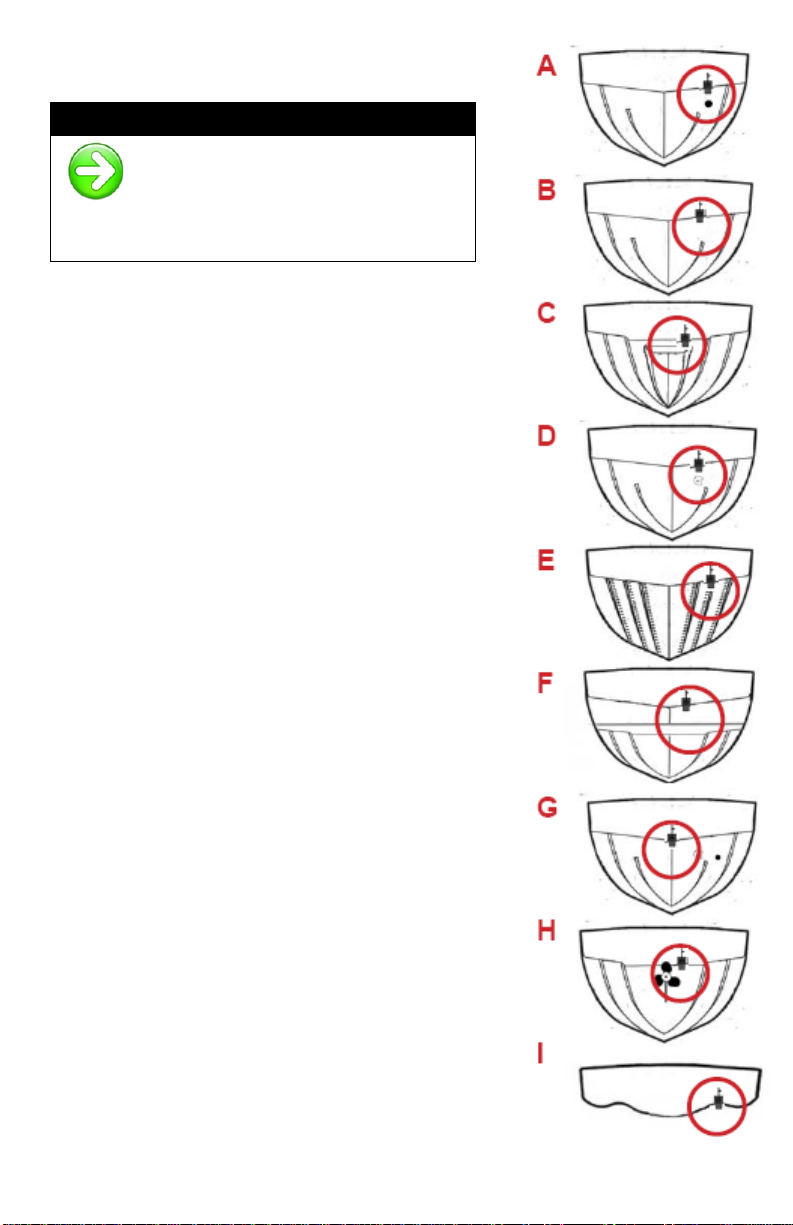
•Have someone run the boat on plane for you in smooth water.
CAREFULLY look over the transom at the water flowing from the bottom

www.hawkeyeelectronics.com
of the boat over the base of the transducer. The water should be "Clean"
with very little turbulence (air bubbles). If there are any air bubbles or
turbulence seen passing underneath the transducer, move the transducer
farther down on the transom bracket. If the performance does not
improve, move the transducer to "Clean Water" making sure to fill any
unused screw holes with marine sealant.
NOTICE
High Speed performance of the depth sounder may require
extensive adjustment and testing to find the best transducer
mounting location. This transducer has been tested to perform
up to 63 MPH in an In-
Hull application. Not all boat hull
configurations will allow for this type of performance. If you are not
satisfied with the performance of the depth sounder, it is recommended
that you seek the advice of a professional marine electronics installer.
GLUING THE TRANSDUCER IN-HULL
N
OTICE
:
Please use extreme caution when selecting your
adhesive as the overall performance and enjoyment
of your depth sounder depends heavily on the type of
adhesive you use. USE ONLY A 2-
PART, SLOW CURE
EPOXY
Tools and Supplies Required
•Plastic Bag
•Petroleum Jelly
•30 Grit Sandpaper
•2 Part Epoxy Adhesive
•Tie Wraps
Vessel Hull Types Acceptable for In-Hull Installation
•High speed boats to increase the performance of the depth sounder.
•Trailer boats to prevent accidental damage to the transducer from
trailering.
•Shallow draft boats to prevent accidental damage to the transducer from
intentional or unintentional ground.
•NON-CORED hulls or aluminum hulls thinner than 1/8”.
•Inboard vessels that have a lot of running gear that creates significant
turbulence.

www.hawkeyeelectronics.com
STEP 1
Choosing a Mounting Location
Since the hull absorbs acoustic energy, transmitting
through the hull reduces the transducers
performance. Fiberglass hulls are often reinforced
in places for added strength. These cored areas
contain wood or structural foam which are poor
sound conductors. To achieve optimal performance,
find a location where the hull’s laminate is solid (not
cored).
To obtain the best performance, the transducer
should be mounted in a location where the water
flow beneath the hull is aeration and turbulence-
free. Try to mount the transducer as close to the
centerline of the boat as possible. Consult the boat
manufacturer for the best in-hull transducer
placement. If this information is unavailable, follow
the guidelines below.
A. Outboard, Inboard/Outboard Powerboats -
Install as close to the stern and centerline
as possible.
B. Inboard Powerboats - Install forward of the
propeller(s), shaft(s), and running gear, as
close to the centerline as possible. Keep in
mind that many Ski Boats have fins that you
need to avoid mounting near.
C. Jet Boats - Install forward of the intake
grate, as close to the centerline as possible.
D. Stepped Hulls - Install forward of the step,
as close to the centerline as possible.
E. Sailboats - Install near the centerline of the
hull and forward of the leading edge of the
keel.
F. Personal Watercraft (PWC) - Install forward
of the intake grate, as close to the
centerline as possible (under the engine).
N
OTICE
:
If your hull is not SOLID fiberglass or up to 1/8th” Aluminum, this
transducer CAN NOT be mounted in-hull. Refer to the Transom
Mounting Instructions, or email us at support.norcrossmarine.com
to inquire about exchanging the transducer.

www.hawkeyeelectronics.com
Mounting Location “DONT’s”
N
OTICE
:
To deliver consistent, accurate
readings, the transducer must have
a continuous supply of non-
turbulent water. Do not mount the transducer
in an area of turbulence or bubbles.
Never install the transducer where the boat may be
supported during trailering, launching, hauling, or
storage. Hull flexing may cause air pockets to form in
the 2 Part Epoxy used to bond the transducer to the
hull which over time will reduce the performance of the
depth sounder.
W
ARNING
:
Never install the transducer without
testing the installation as per Step 2
below.
NEVER MOUNT:
A. Behind water intakes, discharge openings or
thru hull fittings.
B. Behind strakes, struts, or hull irregularities.
C. Behind transom steps or pockets.
D. Behind eroding paint, hull deformities, or
marine growth.
E. Behind rivets or strakes on aluminum boats.
F. Behind the step on stepped hulls.
G. Directly on the “V” in the hull.
H. Behind propellers or anywhere propeller
turbulence will interrupt the flow of “clean”
water to the transducer.
I. In areas where the hull has a reverse angle.
N
OTICE
:

www.hawkeyeelectronics.com
To get a good “view” of the mounting location, while the
vessel is out of the water, position yourself at the
transom and look at the bottom of the hull towards the
bow. Using illustrations A thru I, note anything that could interrupt
the clean flow of water to the transducer mounting location.
STEP 2
Test the Selected Location
1. Anchor/Moor the vessel in a body of water away from other boat traffic.
N
OTICE
:
Turn OFF all other sonar devices on
your boat and locate the vessel at
least 50 feet from the nearest vessel.
2. Plug the transducer cable into the back of the depth
sounder display and turn the display ON. Once the
display is turned ON, it will display the test sequence
and then display the current depth. Make sure the Keel
Offset feature is turned OFF.
3. Place the transducer close to your ear (do not press up
against your ear). If the transducer is properly
connected it will be emitting a ticking sound (similar to a
wrist watch). If you do not hear this ticking sound,
recheck your connections or visit our Customer Service
Center for advanced troubleshooting.
4. Hold the transducer over the side of the vessel so that it
is the same distance below the water surface as it would
be at the in-hull mounting location. Note the depth that is
being displayed on the Depth Sounder.
N
OTICE
:
Certain environmental conditions may
restrict the performance of the depth
sounder. Extremely dirty water, very
soft bottom, high speeds, deep water, or a
combination of the above will result in incomplete
or inaccurate readings. If “-- -” appears on the
display, relocate the vessel to cleaner water.

www.hawkeyeelectronics.com
5. Remove the transducer from the water. Use one of the methods below to test
the depth readings with the transducer at the desired in-hull location selected
in Step 1.
A. If the hull surface is not smooth, sand it with 30 grit sandpaper until a
smooth surface is obtained. Partially fill a thin plastic bag with water,
place the transducer inside and close it tightly with a tie wrap. Wet the
surface of the hull and press the transducer face against the hull through
the bag. Proceed to # 6.
B. If the transducer will be located in an area in the hull that holds water,
place the transducer against the hull and allow bilge water to cover the
surface where the transducer touches the hull. Proceed to # 6.
C. If the hull surface is not smooth, sand it with 30 grit sandpaper until a
smooth surface is obtained. Coat the face of the transducer with
petroleum jelly and press it against the hull with a twisting motion. Use
duct tape to hold it in place. Proceed to # 6.
N
OTICE
:
One of the easiest ways to
temporarily secure the transducer
in hull is by following 5-
B and
wrapping the cable around the
transducer as pictured.
6. If “---” readings appear or the readings are noticeably different from the
depth displayed when the transducer was hung over the side of the boat, you
will need to find another location. If the readings are similar mark the spot in
the hull and proceed to # 7.
7. Temporarily anchor the transducer on the marked spot using duct tape.
8. Remove the vessel from its mooring and operate it at idle speeds while
getting to know the functions and performance of the depth sounder.
9. Gradually increase the boat speed and observe the depth readings (make
sure you stay in water between 2.5 and 200 feet deep).
10. If “---” readings appear:
•Put the vessel in a slow turn. If “---” disappears when turning, the
transducer’s position probably needs adjustment because it is in aerated
water.
•If “---” does not disappear while turning, relocate the transducer using any
one of the methods in # 5 and repeat #5 thru #10.
•If following 5-B, make sure that your “---” readings are not caused by the
bilge water flowing away from the transducer face while turning,
accelerating or decelerating.

www.hawkeyeelectronics.com
11. DO NOT proceed to the next step until you are satisfied with the readings. If
you have difficulties please visit our support website at
support.norcrossmarine.com for technical assistance.
STEP 3
Gluing the Transducer In Place
1. All surfaces to be bonded must be smooth, clean and dry.
If the hull surface is not smooth, sand it with 30 grit
sandpaper until a smooth surface is obtained in an area a
little larger in diameter than the length of the transducer.
2. Clean and dry both the selected area and the face of the
transducer with a weak solvent to remove any dust, grease
or oil.
3. Prepare the adhesive as per the directions supplied with
the adhesive (DO NOT mix the epoxy on the transducer).
4. Apply a generous amount of adhesive to the entire face of
the transducer (side opposite from the cable) and the
inside of the hull.
5. Press the transducer face onto the hull with a twisting
motion to expel all air bubbles. (If the hull is slanted,
temporarily secure the transducer in place with duct tape.)

www.hawkeyeelectronics.com
Allow the adhesive to cure as per the manufacturer’s instructions.
N
OTICE
:
Try to align the transducer
so that the point is aimed
at the bow of the vessel.
STEP 4
Routing the Cable
1. After the adhesive has cured, route the cable the mounting location of the
depth sounder transducer plug. To reduce electrical interference, separate
the transducer cable from other electrical wiring. Coil any excess cable and
secure it in place using tie-wraps.
2. Plug the cable into the corresponding cable on the
Digital Depth Sounder display.
STEP 5
Testing and Troubleshooting the Glue-In Installation
N
OTICE
:
High Speed performance of the depth sounder may require
extensive adjustment and testing to find the best transducer
mounting location. This transducer has been tested to perform up
to 70 MPH in an In-Hull application. Not all boat hull configurations will allow
for this type of performance. If you are not satisfied with the performance of
the depth sounder, it is recommended that you seek the advice of a
professional marine electronics installer.
To Test Your Transducer Installation:
1. Make sure that the display is functioning properly by following the display
testing procedures in the Display Installation and Operation Manual.
2. Place the vessel in the water. Once the display is turned ON, it will display
the test sequence and then display the current depth.

www.hawkeyeelectronics.com
N
OTICE
:
If “---” appears on the display, make sure that there is
at least 2.5 feet of water between the bottom of the
transducer and the bottom of the water body. Also
make sure that the Keel Offset feature is turned OFF.
3. Become familiar with the depth sounders function and performance at idle
speeds.
4. Gradually increase the boat speed and observe the depth readings (pay
attention to minimum and maximum depth capabilities).
5. If you are not happy with the readings there are very little adjustments that
you can do at this time. You will need to remove the transducer and return to
Step 1 of the Glue-In Instructions.
N
OTICE
:
Certain environmental conditions may restrict the
performance of the depth sounder. Extremely dirty water,
very soft bottom, high speeds, deep water, or a combination
of the above will result in incomplete or inaccurate readings. Please
refer to Steps 1 & 2 of this section to minimize the effects of these
conditions. If you are not happy with the performance of your depth
sounder, please
visit our support website at
support.norcrossmarine.com for technical support. Rest assured that
this depth sounder is engineered to the highest standards and is part
of the best selling family of depth sounders in the world. It is highly
likely that your dissatisfaction is due to improper installation and/or
setup, and our technical support resources can get your system
working properly.
To Remove the Transducer:
1. Place a piece of wood against the base of the
transducer.
2. Gently “TAP” the piece of wood with a hammer. DO
NOT strike the transducer directly.
3. Once the transducer is removed from the hull, sand
the excess epoxy adhesive off with sandpaper (minor
sandpaper scratches will not harm the transducer).
DO NOT use chemicals to remove the excess epoxy

www.hawkeyeelectronics.com
TROUBLESHOOTING AND FREQUENTLY ASKED QUESTIONS
24-Hour Technical Support is available online at hawkeyeelectronics.com.
Search our online Knowledgebase for the latest troubleshooting and FAQ’s, or
post your own question for our support staff. For one-on-one support please
email customerservice@norcrossmarine.com.
Sonar Cross Talk:
If you experience incorrect depth readings on your Digital Depth Sounder display,
but nothing on another fish finder screen on the same boat (or vice versa) then
you are experiencing sonar cross-talk interference. The only real solution is to
move the transducers further away from each other. This can help keep the
transducer cones from intersecting, but because cones get wider as the depth
increases, the problem can not usually be completely solved by position only.
Changing one of the sounders to another model that runs on a different
frequency will solve the problem.
Using A Non-Standard Transducer:
You may be able to use a transducer that is currently installed in your watercraft
or a specialized transducer. You need to be sure that the transducer runs on
200Khz and is able to put out 250 watts of transmitting power. If you are unsure
of the specifications please contact the manufacturer. If you need to attach a
non-standard transducer to the Digital Depth Sounder display, order part # ACC-
DF-1130 from our website. Strip back the rubber cable cover 1” (28 mm)
exposing the three internal wires (blue, white, and bare) on your transducer.
Using a soldering iron, solder the blue, white and bare wires from the ACC-DF-
1130 extension cable to the corresponding wires on your transducer. Using
electrical tape, or heat shrink tubing make certain that the soldered connections
are completely sealed and protected against accidental electrical interference
and corrosion. Cutting the plug off the Digital Depth Sounder display will void the
warranty.
Poor Performance:
If you are not happy with the performance of your depth sounder, please visit our
support website at support.norcrossmarine.com for technical support. Rest
assured that this depth sounder is engineered to the highest standards and is
part of the best selling family of depth sounders in the world. It is highly likely
that your dissatisfaction is due to improper installation and/or setup and our
technical support resources can get your system working properly.
REPLACEMENT PARTS
Individual components are not available for sale on our website. If you need
replacement parts, please email our customer service department.
WARRANTY
This device is covered by a 2 Year Limited Warranty. To be eligible for warranty
coverage, you must register your product within 15 days of purchase. Visit our
website for warranty details and to register.

www.hawkeyeelectronics.com
To Activate Your Warranty:
•Read and print out a copy of the warranty details for your records.
•Complete the registration form our website.
•Make a copy of your original purchase receipt and staple it to this manual.
You will need to present it in the rare occurrence that you need to send
your product in for service.
•Complete the information below and store this manual in a safe place.
You can print additional copies of this manual from our website.
I
NFORMATION
:
To aid in maintenance and service, record the following:
Date of Purchase: ___________________
Place of Purchase: _____________________________________
Date of Online Warranty Registration: _____________________
Production Date Code : ________ (3 digit code located on the device housing)
LEGAL
INFORMATION:
MADE IN CHINA, Designed and Supported in the USA. Tested
to comply with FCC, CE & ROSH standards if applicable. Visit our
website for compliance and warranty information. All Specifications
and Prices Subject to Change Without Notice.
NorCross Marine Products, Inc
support.norcrossmarine.com
support@norcrossmarine.com
www.norcrossmarine.com V4916
W
ARNING
:
© 2018 NorCross Marine Products Inc., All Rights Reserved. ALL
unauthorized copying of the content of this document without the
expressed written consent of NorCross Marine Products, Inc is
strictly forbidden.
Table of contents
Other Norcross Marine Equipment manuals
Popular Marine Equipment manuals by other brands

Garmin
Garmin GHP 10 installation instructions

NASA Marine
NASA Marine Cruiser Log Installation and user instructions

Lewmar
Lewmar CPX0- 500W product manual

Pro Charging Systems
Pro Charging Systems DUAL PRO Patriot Series Assembly, installation and operating instructions

Airmar
Airmar SmartFlex SmartBoat ASM-C-T1-1 user manual

NexSens
NexSens CB-40 Data Buoy quick start guide