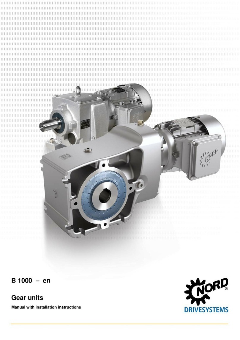
Nord Drivesystems B 1000 Product guide

B 1000 – en
Gear units
Operating and Assembly Instructions

Gear units – Operating and Assembly Instructions
2 B 1000 en-4419
Pos: 4/ A nl eit ung en /G etr i eb e/ 0. Prol og /_ Pr ol og : A nl ei tu ng l e se n @ 22\mod_1531815669201_388.docx@ 2433301@ @ 1
Read the operating and installation instructions
Read this operating and installation manual carefully prior to performing any work on or putting the
gear unit into operation. Always observe the instructions in this operating and assembly manual.
Keep this operating and installation manual in the vicinity of the gear unit so that it is available if
required.
Please also note the following documents:
• Gear unit catalogues (G1000, G1012, G1014, G1035, G1050, G2000),
• Operating and maintenance instructions for the electric motor,
• Operating instructions for equipment which is attached or provided.
Please contact Getriebebau NORD GmbH & Co. KG if you require further information.
Pos: 5/ Al lg emei n/ All ge mei ngül tig e M odul e/ ---------- Seitenumbruch---------- @ 1\mod_1329145698658_0.docx @ 15891 @ @ 1

Documentation
B 1000 en-4419 3
Pos: 6/ A nl eit ung en /G etr i eb e/ 0. Prol og /D ok u men tat i o n - Versionsliste[B 1000]@ 39\mod_1572856925662_388.docx@ 2571050@ @ 1
Documentation
Designation:
B 1000
Material No.:
6052802
Series: Gear units and geared motors
Type series:
Gear unit
types:
Helical gear units
NORDBLOC helical gear units
Standard helical gear units
Parallel shaft gear units
Bevel gear units
Helical worm gear units
MINIBLOC worm gear units
UNIVERSAL worm gear units
Version list
Title,
Date
Order
number
Remarks
B 1000,
February 2013
6052802 /
0713
-
B 1000,
September 2014
6052802 /
3814
• General corrections
B 1000,
April 2015
6052802 /
1915
• New gear unit types SK 10382.1 + SK 11382.1
B 1000,
March 2016
6052802 /
0916
• General corrections
• New bevel gear units SK 920072.1 + SK 930072.1
B 1000,
September 2016
6052802 /
3816
• General corrections
• New helical gear units SK 071.1, SK 171.1, SK 371.1, SK 571.1,
SK 771.1;
B 1000 June
2018
6052802 /
2518
• General corrections
• New parallel shaft gear units SK 0182.1, SK 0282.1, SK 1282.1,
SK 1382,1
• New worm gear unit SK 02040.1
B 1000
December 2018
6052802 /
5018
• General corrections
• Revision of safety and warning information
• New parallel shaft gear units NORDBLOC SK 871.1, SK 971.1, SK
1071.1
B 1000 October
2019
6052802 /
4419
• General corrections
• Addition of GRIPMAXX™ (Option M)
Table 1: Version list B 1000
Pos: 10 /Al lg emei n/Al lg em eing ülti ge M od ule/ ---------- Seite num bruc h ---------- @ 1\mod_1329145698658_0.docx@ 15891@ @ 1

Gear units – Operating and Assembly Instructions
4 B 1000 en-4419
Pos: 11 /Al lg e mei n/ All ge mei ng ül tig e M od ul e/U rh e berr ec hts v erm er k @ 5\mod_1410955083459_388.docx@ 150427@ @ 1
Copyright notice
As an integral component of the device described here, this document must be provided to all
users in a suitable form.
Any editing or amendment or other utilisation of the document is prohibited.
Pos: 12 /Al lg em ein /All ge mei ng ült ig e M odul e/ H era usge ber @ 0\mod_1325779078002_388.docx@ 5270@ @ 1
Publisher
Getriebebau NORD GmbH & Co. KG
Getriebebau-Nord-Straße 1 • 22941 Bargteheide, Germany • http://www.nord.com/
Fon +49 (0) 45 32 / 289-0 • Fax +49 (0) 45 32 / 289-2253
Member of the NORD DRIVESYSTEMS Group
===Ende der Lis t e f ür Te xtm ar ke Cop yrig ht ===

Publisher
B 1000 en-4419 5

Gear units – Operating and Assembly Instructions
6 B 1000 en-4419
Pos: 14 /Al lg e mei n/ Ste u erm o dul e/I nhal t s verz eic hni s @ 0\mod_1317978518480_388.docx@ 4078@ @ 1
Table of Contents
=== E nde der List e f ür T e xt mar ke I nh alt s ver z ei ch nis = = =
1Safety information.....................................................................................................................................10
1.1 Intended use ....................................................................................................................................10
1.2 Do not make any modifications. .......................................................................................................10
1.3 Performing inspection and maintenance work .................................................................................10
1.4 Personnel qualification.....................................................................................................................10
1.5 Safety for particular activities ...........................................................................................................11
1.5.1 Check for transport damage ...............................................................................................11
1.5.2 Safety information for installation and maintenance ...........................................................11
1.6 Hazards............................................................................................................................................11
1.6.1 Hazards when lifting ...........................................................................................................11
1.6.2 Hazards due to rotating parts .............................................................................................11
1.6.3 Hazards due to high or low temperatures...........................................................................12
1.6.4 Hazards due to lubricants and other substances................................................................12
1.6.5 Hazards due to noise..........................................................................................................12
1.6.6 Hazards due to pressurised coolants .................................................................................12
1.7 Explanation of markings...................................................................................................................13
2Description of gear units ..........................................................................................................................14
2.1 Type designations and gear unit types.............................................................................................14
2.2 Type plate ........................................................................................................................................16
3Assembly instructions, storage, preparation, installation ....................................................................17
3.1 Transporting the gear unit................................................................................................................17
3.2 Storage ............................................................................................................................................17
3.3 Long-term storage............................................................................................................................18
3.4 Preparing for installation ..................................................................................................................19
3.5 Installing the gear unit......................................................................................................................21
3.6 Fitting hubs on the gear shafts.........................................................................................................22
3.7 Fitting push-on gear units.................................................................................................................24
3.8 Fitting shrink discs............................................................................................................................27
3.8.1 Hollow shaft with shrink disc (Option S) .............................................................................27
3.8.2 Hollow shaft with GRIPMAXX™ (Option M) .......................................................................29
3.9 Fitting the covers..............................................................................................................................31
3.10 Fitting the covers..............................................................................................................................32
3.11 Fitting a standard motor ...................................................................................................................33
3.12 Fitting the cooling coil to the cooling system....................................................................................35
3.13 External oil-air cooler .......................................................................................................................36
3.13.1 Assembling the cooling system ..........................................................................................36
3.13.2 Oil-air cooler electrical connection......................................................................................36
3.14 Installation of an oil expansion tank, Option OA...............................................................................37
3.15 Subsequent painting ........................................................................................................................37
4Commissioning .........................................................................................................................................38
4.1 Check the oil level............................................................................................................................38
4.2 Activating the automatic lubricant dispenser....................................................................................38
4.3 Operation with lubricant cooling .......................................................................................................39
4.4 Running-in time for the worm gear unit ............................................................................................39
4.5 Checklist ..........................................................................................................................................40
5Service and maintenance .........................................................................................................................41
5.1 Service and Maintenance Intervals ..................................................................................................41
5.2 Service and Maintenance Work .......................................................................................................42
6Disposal .....................................................................................................................................................46

Table of Contents
B 1000 en-4419 7
7Appendix....................................................................................................................................................47
7.1 Versions and maintenance...............................................................................................................47
7.2 Lubricants ........................................................................................................................................62
7.3 Lubricant quantities..........................................................................................................................65
7.4 Screw tightening torques..................................................................................................................73
7.5 Troubleshooting ...............................................................................................................................74
7.6 Leakage and leak-tightness .............................................................................................................75
7.7 Repair information............................................................................................................................76
7.7.1 Repairs ...............................................................................................................................76
7.7.2 Internet information.............................................................................................................76
7.8 Warranty ..........................................................................................................................................76
7.9 Abbreviations ...................................................................................................................................77

Gear units – Operating and Assembly Instructions
8 B 1000 en-4419
Pos: 16 /Al lg e mei n/ Ste u erm o dul e/ Abbi ld ung s ver z eich nis @ 0\mod_1317978515699_388.docx@ 3917 @ @ 1
List of illustrations
=== E nde der List e f ür T e xt mar ke A b bil du ng s ver zei c h nis = = =
Figure 1: Type plate (example) with explanation of type plate fields ..................................................................... 16
Figure 2: Activating the vent screw........................................................................................................................ 20
Figure 3: Activating the pressure vent screw......................................................................................................... 20
Figure 4: Removing the vent plug and fitting the special pressure vent................................................................. 20
Figure 5: Example of a simple pulling device ........................................................................................................ 22
Figure 6: Permissible application of force to drive and driven shafts..................................................................... 23
Figure 7: Applying lubricant to the shaft and the hub............................................................................................. 24
Figure 8: Removing the factory-fitted closing cap.................................................................................................. 25
Figure 9: Gear unit mounted on shaft with a shoulder using the fastening element .............................................. 25
Figure 10: Gear unit mounted on shaft without a shoulder using the fastening element ....................................... 25
Figure 11: Removal using dismantling device ....................................................................................................... 25
Figure 12: Mounting the rubber buffer (Option G and/or VG) on parallel shaft gear units ..................................... 26
Figure 13: Attaching the torque support on bevel gear and worm gear units ........................................................ 26
Figure 14: Hollow shaft with shrink disc................................................................................................................. 27
Figure 15: GRIPMAXX™, installed........................................................................................................................ 29
Figure 16: GRIPMAXX™, exploded diagram ........................................................................................................ 30
Figure 17: Fitting the covers, Option SH, Option H, and Option H66..................................................................... 31
Figure 18: Removal and fitting of the cover cap .................................................................................................... 32
Figure 19: Fitting the coupling onto the motor shaft - various types of coupling .................................................... 34
Figure 20: Cooling cover ....................................................................................................................................... 35
Figure 21: Connecting the cooling system............................................................................................................. 36
Figure 22: Installing the expansion tank ................................................................................................................ 37
Figure 23: Fitting the grease collection container.................................................................................................. 38
Figure 24: Activating the automatic lubricant dispenser with standard motor mounting ........................................ 39
Figure 25: Adhesive label ...................................................................................................................................... 39
Figure 26: Checking the oil level with a dipstick .................................................................................................... 43
Figure 27: Replacing the automatic lubricant dispenser with standard motor mounting........................................ 44
Figure 28: Oil level check with oil level tank .......................................................................................................... 48

List of tables
B 1000 en-4419 9
Pos: 18 /Al lg e mei n/ Ste u erm o dul e/T ab ell en ver zei c hni s @ 0\mod_1317978519199_388.docx@ 4124@ @ 1
List of tables
=== E nde der List e f ür T e xt mar ke T ab el le n verz ei c hni s ===
Table 1: Version list B 1000..................................................................................................................................... 3
Table 2: Type designations and gear unit types .................................................................................................... 15
Table 3: Permissible machine shaft tolerances ..................................................................................................... 29
Table 4: Disposal of materials ............................................................................................................................... 46
Table 5: Roller bearing greases............................................................................................................................. 62
Table 6: Lubricant table ......................................................................................................................................... 64
Table 7: Lubricant quantities for helical gear units................................................................................................. 66
Table 8: Lubricant quantities for NORDBLOC ....................................................................................................... 67
Table 9: Lubricant quantities for NORDBLOC helical gear units ........................................................................... 68
Table 10: Lubricant quantities for standard helical gear units................................................................................ 69
Table 11: Lubricant quantities for parallel shaft gear units .................................................................................... 70
Table 12: Lubricant quantities for bevel gear units ................................................................................................ 71
Table 13: Lubricant quantities for helical worm gear units..................................................................................... 72
Table 14: Screw tightening torques ....................................................................................................................... 73
Table 15: Overview of malfunctions....................................................................................................................... 74
Table 16: Definition of leaks according to DIN 3761.............................................................................................. 75
Pos: 21.1 / Anl eit ung e n/G etr ie be/ 1. Hin wei s e/Sic h erh ei ts hin wei s e/0 1. Si c h erh eits hi n wei se [ _T it el] @ 22\mod_1530531998385_388.docx@ 2429407@ 1 @ 1

Gear units – Operating and Assembly Instructions
10 B 1000 en-4419
1 Safety information
Pos: 21.2 .1 / A nlei t ung e n/ Ge tr ieb e/ 1. Hin wei se /S ic h er h eits hi n wei se /B es ti m mung s g em äß e Verw en dung 0 1 [ Ge tr i ebe M R L/ EAC ] @ 33\mod_1559642322419_388.docx @ 2537975@2 @ 1
1.1 Intended use
These gear units are used to transmit and transform rotary movements. They are intended for use as
part of a drive system in commercially used plant and machinery. The gear units must not be operated
until it has been established that the plant or machinery can be safely operated with the gear unit.
Suitable protective measures must be provided if failure of a gear unit or a geared motor could result
in a risk to persons. The machine or system must comply with local legislation and directives. All
applicable health and safety requirements must be met. In particular, the Machinery Directive
2006/42/EC, TR CU 010/2011 and the TR CU 020/2011 must be especially observed in the relevant
areas of application.
Pos: 21 .2.3 /A nleit unge n/Getr iebe/ 1. Hinw eise/S ich erheits hin weise/ Besti mmung sgem äße Ver wend ung 02 [Ge trieb e kein e x] @ 33\mod_1559642580030_388.docx@ 2538049@ @ 1
The gear units may not be used in environments in which an explosive atmosphere can occur.
Pos: 21.2 .4 / A nlei t ung e n/ Ge tr ieb e/ 1. Hin wei se /S ic h er h eits hi n wei se /B es ti m mung s g em äß e Verw en dung 0 3 [ Ge tr i ebe] @ 3 3\m od_1559642705569_388.docx@2538086@ @ 1
The gear units may only be used according to the information in the technical documentation from
Getriebebau NORD GmbH & Co. KG. Damage to the gear unit may result if the gear unit is not used
as intended and according to the information in the operating and assembly manual. This may also
result in personal injury.
The base or the gear unit mount must be appropriately designed for the weight and torque. All of the
fastenings provided must be used.
Some gear units are equipped with a cooling coil. These gear units may only be operated if the cooling
circuit is connected and in operation.
Pos: 21.5 / Anl eit ung e n/G etr ie be/ 1. Hin wei s e/Sic h erh ei ts hin wei s e/K ei ne V er änd er ung e n v orn eh me n @ 22\mod_1531467922067_388.docx@ 2433140@ 2 @ 1
1.2 Do not make any modifications.
Do not make any modifications to the gear unit. Do not remove any protective devices.
Pos: 21.6 / Anl eit ung e n/G etr ie be/ 1. Hin wei s e/Sic h erh ei ts hin wei s e/I ns pe ktio ne n u nd Wart ung dur ch führ e n @ 22\mod_1530529678502_388.docx@ 2429333@2 @ 1
1.3 Performing inspection and maintenance work
Due to lack of maintenance and damage, malfunctions may occur which can result in personal injury.
• Carry out all servicing and maintenance work at the specified intervals.
• Also note that servicing is necessary after long storage periods prior to commissioning.
• Do not operate damaged gear units. The gear unit must not have any leaks.
Pos: 21.7 / Anl eit ung e n/G etr ie be/ 1. Hin wei s e/Sic h erh ei ts hin wei s e/P ers on alq u ali fi kat io n @ 2 2\mod_1530534446474_388.docx@ 2429521@ 2 @ 1
1.4 Personnel qualification
All transport, storage, installation, commissioning and maintenance work must be carried out by
qualified specialist personnel.
Qualified specialist personnel are persons who have the training and experience to recognise and
avoid any possible risks.
Pos: 21.8 / Allg em ein /Allg em eing ült ige M od ul e/---------- Seite num br uc h ---------- @ 1\mod_1329145698658_0.docx@ 15891@ @ 1

1 Safety information
B 1000 en-4419 11
Pos: 21.9 .1 / A nlei t ung e n/ Ge tr ieb e/ 1. Hin wei se /S ic h er h eits hi n wei se /Si c h er hei t bei b esti mmt e n T äti g keit e n [ _T it el ] @ 22\mod_1531811512686_388.docx@ 2433220@ 2@ 1
1.5 Safety for particular activities
Pos: 21.9 .2 /A nl ei tu nge n/ Ge tri eb e/1. Hin wei se /Si c her h eits hi nw eis e/A uf Tra ns ports c hä de n k ont rol lier en @ 2 2\mod_1530528472640_388.docx@ 2429296@ 3 @ 1
1.5.1 Check for transport damage
Transport damage may cause malfunctions of the gear unit, which may cause personal injury. Oil
which escapes due to leaks may cause a slipping hazard.
• Check the packaging and the gear unit for transport damage.
• Do not operate damaged gear units.
Pos: 21.9 .3 / A nlei t ung e n/ Ge tr ieb e/ 1. Hin wei se /S ic h er h eits hi n wei se /Si c h er hei ts hi n wei se für I nst al l at io n und I ns ta n dh alt ung @ 22\mod_1530537922788_388.docx@ 2429600@3 @ 1
1.5.2 Safety information for installation and maintenance
Before starting work on the gear unit disconnect the drive from the power supply and secure it against
accidental switch-on. Allow the gear unit to cool down. Depressurise the cooling circuit lines.
Damaged or defective components, attachment adapters, flanges and covers may have sharp edges.
Wear work gloves and work clothing.
Pos: 21.1 0. 1 / A nl eit u ng en /G etr ie b e/ 1. Hi n weis e/ Si c her heit s hi n weis e/ G efä hr du nge n [ _Ti t el ] @ 22\mod_1531812422755_388.docx@ 2433257@ 2@ 1
1.6 Hazards
Pos: 21.1 0. 2 / A nl eit u ng en /G etr ie b e/ 1. Hi n weis e/ Si c her heit s hi n weis e/ G efä hr du nge n beim Anheb e n 01 @ 34\mod_1559807063051_388.docx@ 2539250@ 3 @ 1
1.6.1 Hazards when lifting
Persons may be injured by falling or swinging gear units. Therefore also observe the following
information:
• Cordon off a wide area around the hazard area. Take care that there is adequate space to avoid
swinging loads.
• Never stand under suspended loads.
• Use adequately dimensioned means of transport which are suitable for the purpose. The weight of
the gear unit can be obtained from the type plate.
Pos: 21.1 0. 3 / A nl eit u ng en /G etr ie b e/ 1. Hi n weis e/ Si c her heit s hi n weis e/ G efä hr du nge n beim Anheb e n 02 [G etr i eb e] @ 3 4\mod_1559808648235_388.docx@ 2539334@ @ 1
• Only lift the gear units by the eye bolts which are provided. The eye bolts must be fully screwed in.
Only pull on the eye bolts vertically, never cross-wise or at an angle. Only use the eye bolts to lift
the gear unit without other components. The eye bolts are not designed for lifting the gear unit with
attachments. Use the eye bolts on both the gear unit and the motor to lift a geared motor.
Pos: 21.1 0. 5 / A nl eit u ng en /G etr ie b e/ 1. Hi n weis e/ Si c her heit s hi n weis e/ G efä hr du ng d ur c h r o ti er en de Teil e @ 22\mod_1530538419628_388.docx@ 2429637@ 3 @ 1
1.6.2 Hazards due to rotating parts
Rotating parts cause a risk of entanglement. Therefore provide a contact guard. In addition to shafts,
this also applies to fans as well as drives and drive elements such as belt drives, chain drives, shrink
discs and couplings.
For test operation do not switch on the drive without an installed drive element or secure the parallel
key.
Take possible run-on of the machine into consideration for the design of protective guards.

Gear units – Operating and Assembly Instructions
12 B 1000 en-4419
Pos: 21.1 0. 6 / A nl eit u ng en /G etr ie b e/ 1. Hi n weis e/ Si c her heit s hi n weis e/ G efä hr du nge n durc h ho h e od er tief e T e mp era tur en @ 2 2\mod_1530531214142_388.docx@ 2429370@ 3 @ 1
1.6.3 Hazards due to high or low temperatures
The gear unit may heat up to 90 °C during operation. Touching hot surfaces or contact with hot oil may
result in burns. At very low ambient temperatures freezing may occur on contact.
• Only touch the gear unit when wearing gloves after operation or at very low ambient temperatures.
• Before starting maintenance work, allow the gear unit to cool down sufficiently after operation.
• Provide a contact guard if there is a risk that persons may touch the gear unit when it is in
operation.
• Bursts of hot oil mist may be emitted from the pressure vent screw during operation. Provide a
suitable guard so that persons cannot be injured by this.
• Do not place any flammable materials on the gear unit.
Pos: 21.1 0. 7 / A nl eit u ng en /G etr ie b e/ 1. Hi n weis e/ Si c her heit s hi n weis e/ G efä hr du nge n durc h Sc hmi ers t off e und a n der e S u bst a nze n @ 22 \mo d_1530535266235_388.docx@ 2429558@ 3 @ 1
1.6.4 Hazards due to lubricants and other substances
Chemical substances which are used with the gear unit may be toxic. Eye injuries may result if these
substances enter the eyes. Lubricants and adhesives may cause skin irritation.
Oil mist may escape when vent screws are opened.
Due to lubricants and conservation materials, gear units may be slippery and slip out of the hands.
There is a slipping hazard from spilled lubricants.
• When working with chemical substances wear chemical-resistant gloves and work clothing. Wash
your hands after working.
• Wear protective goggles if there is a possibility of splashed chemicals, for example when filling oil
or during cleaning work.
• If chemicals enter the eyes, rinse with large amounts of cold water immediately. Consult a
physician in case of symptoms.
• Observe the safety data sheets for the chemicals. Keep the safety data sheets in the vicinity of the
gear unit.
• Collect spilled lubricants immediately with a binding agent.
Pos: 21 .1 0. 8 / A nl eit u ng en /G etr ie b e/ 1. Hi n weis e/ Si c her hei t shi n weis e/ G efä hr du ng durc h Lär m @ 22\mod_1530611473949_388.docx@ 2429977@3 @ 1
1.6.5 Hazards due to noise
Some gear units or attached components may cause hazardous noise levels during operation. Wear
hearing protection if work has to be carried out close to such gear units.
Pos: 21.1 0. 9 / A nl eit u ng en /G etr ie b e/ 1. Hi n weis e/ Si c her heit s hi n weis e/ G efä hr du ng d ur c h unt er Dr uc k s t eh en d es Kühl mit t el @ 22\mod_1531484732839_388.docx@ 2433177@ 3 @ 1
1.6.6 Hazards due to pressurised coolants
The cooling system is under high pressure. Damage or opening a cooling line which is under pressure
may result in injury. Depressurise the cooling circuit before working on the gear unit.
Pos: 21.1 1 /Al lge mei n/Al lg emei ngül tig e Module/---------- Seit enu mbr uc h ---------- @ 1\mod_1329145698658_0.docx@ 15891@ @ 1

1 Safety information
B 1000 en-4419 13
Pos:21.12.1/Allgemein/AllgemeingültigeModule/Erläuterungder verwendetenAuszeichnungen01@ 33\mod_1559648695536_388.docx@ 2538130@ 2 @ 1
1.7 Explanation of markings
DANGER
Indicates an immediate danger, which may result in death or very serious injury if it is not avoided.
Pos:21.12.3/Allgemein/AllgemeingültigeModule/Erläuterungder verwendetenAuszeichnungen03@ 33\mod_1559648785625_388.docx@ 2538204@ @ 1
WARNING
Indicates a dangerous situation, which may result in death or very serious injury if it is not avoided.
CAUTION
Indicates a dangerous situation, which may result in minor injuries if it is not avoided.
NOTICE!
Indicates a situation, which may result in damage to the product or its environment if it is not avoided.
Information
Indicates hints for use and especially important information to ensure reliability of operation.
Pos: 23 /A nl eit ung e n/ Ge tr ie be /2. Getr ie b eb esc hr ei b ung / 2. Getr ie be b esc hr eib u ng [Tit el] @ 3\mod_1368691027023_388.docx@ 65591@ 1 @ 1

Gear units – Operating and Assembly Instructions
14 B 1000 en-4419
2 Description of gear units
Pos: 24 /A nlei tunge n/Ge triebe /2. Getr ieb ebeschr eib ung/T ypenb ezeic hnung en und Ge trie beart en [B100 0] @ 39\mod_1573048194638_388.docx@ 2573386@ 2 @ 1
2.1 Type designations and gear unit types
Gear unit types / Type designations
Helical gear units
SK 11E, SK 21E, SK 31E,SK 41E, SK 51E (1-stage)
SK 02, SK 12, SK 22, SK 32, SK 42, SK 52, SK 62N (2-stage)
SK 03, SK 13, SK 23, SK 33N, SK 43, SK 53 (3-stage)
SK 62, SK 72, SK 82, SK 92, SK 102 (2-stage)
SK 63, SK 73, SK 83, SK 93, SK 103 (3-stage)
NORDBLOC helical gear units
SK 320, SK 172, SK 272, SK 372, SK 472, SK 572, SK 672, SK 772, SK 872, SK 972 (2-stage)
SK 273, SK 373, SK 473, SK 573, SK 673, SK 773, SK 873, SK 973 (3-stage)
SK 071.1, SK 371.1, SK 571.1, SK 771.1, SK 871.1, SK 971.1, SK 1071.1 (1-stage)
SK 072.1, SK 172.1, SK 372.1, SK 572.1, SK 672.1, SK 772.1, SK 872.1, SK 972.1 (2-stage)
SK 373.1, SK 573.1, SK 673.1, SK 773.1, SK 873.1, SK 973.1 (3-stage)
Standard helical gear units
SK 0, SK 01, SK 20, SK 25, SK 30, SK 33 (2-stage)
SK 10, SK 200, SK 250, SK 300, SK 330 (3-stage)
Parallel shaft gear units
SK 0182NB, SK 0182.1, SK 0282NB, SK 0282.1, SK 1282, SK 1282.1, SK 2282, SK 3282, SK 4282, SK 5282,
SK 6282, SK 7282, SK 8282, SK 9282, SK 10282, SK 11282 (2-stage)
SK 0182.1, SK 0282.1, SK 1382NB, SK 1382.1, SK 2382, SK 3382, SK 4382, SK 5382, SK 6382, SK 7382,
SK 8382, SK 9382, SK 10382, SK 10382.1, SK 11382, SK 11382.1, SK 12382 (3-stage)
Bevel gear units
SK 92072, SK 92172, SK 92372, SK 92672, SK 92772;
SK 920072.1, SK 92072.1, SK 92172.1, SK 92372.1, SK 92672.1, SK 92772.1, SK 930072.1. SK 93072.1,
SK 93172.1, SK 93372.1, SK 93672.1, SK 93772.1 (2-stage)
SK 9012.1, SK 9016.1, SK 9022.1, SK 9032.1, SK 9042.1, SK 9052.1, SK 9062.1, SK 9072.1, SK 9082.1,
SK 9086.1, SK 9092.1, SK 9096.1 (3-stage)
SK 9013.1, SK 9017.1, SK 9023.1, SK 9033.1, SK 9043.1, SK 9053.1 (4-stage)
Helical worm gear units
SK 02040, SK 02040.1, SK 02050, SK 12063, SK 12080, SK 32100, SK 42125 (2-stage)
SK 13050, SK 13063, SK 13080, SK 33100, SK 43125 (3-stage)
MINIBLOC worm gear units
SK 1S32, SK 1S40, SK 1S50, SK 1S63, SK 1SU..., SK 1SM31, SK 1SM40, SK 1SM50, SK 1SM63 (1-stage)
SK 2S32NB, SK 2S40NB, SK 2S50NB, SK 2S63NB, SK 2SU…, SK 2SM40, SK 2SM50, SK 2SM63 (2-stage)

2 Description of gear units
B 1000 en-4419 15
Gear unit types / Type designations
UNIVERSAL worm gear units
SK 1SI31, SK 1SI40, SK 1SI50, SK 1SI63, SK 1SI75,
SK 1SIS31, …, SK 1SIS75,
SK 1SID31, …, SK 1SID63,
SK 1SMI31, …, SK 1SMI75,
SK 1SMID31, …, SK 1SMID63,
SK 1SIS-D31, …, SK 1SIS-D63 (1-stage),
SK 2SMID40, SK 2SMID50, SK 2SMID63, SK 2SID40, …, SK 2SID63 (2-stage)
Versions / Options
- Foot mounting with solid shaft D Torque support IEC Standard IEC motor mounting
A Hollow shaft version K Torque bracket NEMA Standard NEMA motor
attachment
V
Solid shaft version
S
Shrink disc
W
With free drive shaft
L Solid shaft both sides VS Reinforced shrink disc VI Viton shaft sealing ring
Z B14 output flange EA Solid shaft with geared hub profile OA Oil expansion tank
F
B5 output flange
G
Rubber buffer
OT
Oil level tank
X
Foot mounting
VG
Reinforced rubber buffer
SO1
Synthetic oil ISO VG 220
XZ B14 foot and output flange R Backstop CC Housing cover with cooling spiral
XF B5 foot and output flange B Fastening element M GRIPMAXX™
AL
Axially reinforced output bearings
H
Covering cap as contact guard
DR
Pressure venting
5
Reinforced output shaft
(Standard helical gear units)
H66
IP66 cover
H10
Modular helical pre-stage
V Reinforced drive
(Standard helical gear units)
VL Reinforced bearings /31 Worm gear first stage
VL2
Agitator version
/40
Worm gear first stage
VL3 Drywell agitator version
Table 2: Type designations and gear unit types
Double gear units consist of two single gear units. They are to be treated as per the instructions in this
manual, i.e. as two individual gear units.
Type designation for double gear units: e. g. SK 73 / 22 (consisting of single gear units SK 73 and SK
22).
Pos: 33 /All ge mei n/Al lge mei ng ültig e M odul e/---------- Sei te num bruc h ---------- @ 1\mod_1329145698658_0.docx@ 15891@ @ 1

Gear units – Operating and Assembly Instructions
16 B 1000 en-4419
Pos: 34 /A nl eit ung e n/ Ge tr ie be /2. Getr ie b eb esc hr ei b ung /T yp ens chi l d [ B1 0 00 ] @ 23\mod_1534153999090_388.docx@ 2438707@ 2 @ 1
2.2 Type plate
Explanation
1 Matrix – Barcode
2 NORD gear unit type
3 Operating mode
4 Year of manufacture
5 Serial number
6
Rated torque of gear unit
output shaft
7 Drive power
8
Weight according to ordered
version
9 Overall gear unit ratio
10 Installation orientation
11
Rated speed of gear unit
output shaft
12
Lubricant type,
viscosity and quantity
13 Customer’s part number
14 Operating factor
Figure 1: Type plate (example) with explanation of type plate fields
Pos: 42 /A nleitu ngen/ Getri ebe/3. M ontag e, Lager ung, Vor berei tung, Au fstel lung/3 .M ontag eanl eitung, L ager ung, Vor bereit ung, Aufstellung@ 23\mod_1531915085387_388.docx@ 2434207@ 1 @ 1

3 Assembly instructions, storage, preparation, installation
B 1000 en-4419 17
3 Assembly instructions, storage, preparation, installation
Please note all safety information (please see chapter 1 "Safety information")and warning information
in the relevant sections.
Pos: 43 /A nleitu ngen/ Getri ebe/3. M ontag e, Lager ung, Vor berei tung, Au fstel lung/T rans port/T rans port des Ge triebes 0 1 headl ine @ 34\mod_1559812428776_388.docx@ 2539371@ 2 @ 1
3.1 Transporting the gear unit
Pos: 44 /A nleitu ngen/ Getri ebe/3. M ontag e, Lager ung, Vor berei tung, Au fstel lung/T rans port/T rans port des Ge triebes 0 2 [Stand ardg etrieb e - Ri ng schr au be ] @ 34\mod_1559813589771_388.docx@ 2539562@ @ 1
WARNING
Hazard due to falling loads
• The thread of the eye bolt must be fully screwed in.
• Do not pull on the eye bolt at an angle.
• Note the centre of gravity of the gear unit.
Only use the eye bolts attached to the gear unit for transport. If geared motors have an additional eye
bolt attached to the motor, this must also be used.
Pos: 46 /A nleitu ngen/ Getri ebe/3. M ontag e, Lager ung, Vor berei tung, Au fstel lung/T rans port/T rans port des Get riebes 0 3@ 34 \mod_1559812454553_388.docx@ 2539408@ @ 1
Transport the gear unit with care. Use suitable aids such as cross-beams or similar to facilitate
transportation of the gear unit. Impacts to the free ends of shafts may cause internal damage to the
gear unit.
Pos: 58 /A nl eit ung e n/ Ge tr ie be /3. Mont ag e , L ag er ung , Vorb er ei tu ng , Aufst el lu ng /L ag er ung / Lag eru ng @ 27\mod_1551177486988_388.docx@ 2491276@ 2 @ 1
3.2 Storage
For short-term storage before commissioning, please observe the following:
• Store gear units in the fitting position ((please see chapter 7.1 "Versions and maintenance")) and
secure them against falling,
• Lightly oil bare metal housing surfaces and shafts
• Store in a dry place,
• Temperature in the range from – 5 °C to + 50 °C without large fluctuations,
• Relative humidity less than 60 %,
• No direct exposure to sunlight or UV light,
• No aggressive, corrosive substances (contaminated air, ozone, gases, solvents, acids, alkalis,
salts, radioactivity etc.) in the immediate vicinity,
• No vibration or oscillation

Gear units – Operating and Assembly Instructions
18 B 1000 en-4419
Pos: 61 /A nl eit ung e n/ Ge tr ie be /3. Mont ag e , L ag er ung , Vorb er ei tu ng , Aufst el lu ng /L ag er ung / La ng zei t lag er ung @ 2 2\mod_1531827638482_388.docx@ 2433521@ 2555@ 1
3.3 Long-term storage
For storage or standstill periods in excess of 9 months, Getriebebau NORD recommends the long-
term storage option. With the use of the measures listed below, storage for up to 2 years is possible.
As the actual influences on the unit greatly depend on the local conditions, these times should only be
regarded as guide values.
Conditions of the gear unit and storage area for long-term storage prior to commissioning:
• Store in the fitting position (please see chapter 7.1 "Versions and maintenance")and secure them
against falling.
• Transportation damage to the external paint must be repaired. Check that a suitable rust inhibitor is
applied to the flange bearing surfaces. If necessary apply a suitable rust inhibitor to the surfaces.
• Gear units with the long-term storage option are completely filled with lubricant or have VCI
corrosion protection agent mixed with the gear oil (see adhesive label on the gear unit, or are not
filled with oil, but rather with small quantities of VCI concentrate.
• The sealing band in the vent plug must not be removed during storage. The gear unit must remain
sealed tight.
• Store in a dry place.
• In tropical regions the drive unit must be protected against damage by insects.
• Temperature in the range from – 5 °C to + 40 °C without large fluctuations.
• Relative humidity less than 60 %.
• No direct exposure to sunlight or UV light.
• No aggressive, corrosive substances (contaminated air, ozone, gases, solvents, acids, alkalis,
salts, radioactivity etc.) in the immediate vicinity.
• No vibration or oscillation
Measures during storage or standstill periods
• If the relative humidity is < 50 % the gear unit can be stored for up to 3 years.
Measures before commissioning
• Inspect the gear unit before commissioning.
• If the storage or standstill period exceeds 2 years or the temperature during short-term storage has
greatly deviated from the standard range, the lubricant in the gear unit must be replaced before
commissioning.
• If the gear unit is completely filled, the oil level must be reduced before commissioning.
• For gear units without oil filling, the oil level for the version must be filled before commissioning.
The VCI concentrate may remain in the gear unit. Lubricant quantities and types must be filled
according to the details on the type plate.
Pos: 66 /All ge mei n/Al lge mei ng ültig e M odul e/---------- Sei te num bruc h ---------- @ 1\mod_1329145698658_0.docx@ 15891@ @ 1

3 Assembly instructions, storage, preparation, installation
B 1000 en-4419 19
Pos: 67 / A nl ei tu ng e n/ Ge tr ie be /3. Mo nt ag e, L ag er ung , V or b er ei t ung , Aufs t ell u ng /A ufs t ell en /V orb er ei t u ng en z u m A uf st ell en _ 01 @ 28\mod_1551437422532_388.docx@ 2493987@ 2 @ 1
3.4 Preparing for installation
Pos: 68 /A nleitu ngen/ Getri ebe/3. M ontag e, Lager ung, Vor berei tu ng , Aufs t ell u ng /A ufs t ell en/ V orb er ei t u ng en z u m A uf st ell en 0 2 [B1 00 0] @ 35 \mod_1559824583213_388.docx@ 2539684@ @ 1
Please examine the delivery for transport and packaging damage immediately on receipt. The drive
unit must be examined and may only be installed if no damage is apparent. In particular the shaft
sealing rings and sealing caps must be inspected for damage. Report any damage to the carrier
immediately. Gear units with transport damage must not be commissioned.
All bare metal surfaces and shafts of the gear units are protected against corrosion with oil/grease or
corrosion protection agents before shipping.
Thoroughly remove all oil / grease or corrosion protection agents and any dirt from the shafts and
flange surfaces before assembly.
In applications where an incorrect rotational direction may result in damage or potential risk, the
correct rotational direction of the output shaft must be established by test running the drive when
uncoupled and ensured for subsequent operation.
Gears with integrated back stops are marked with arrows on the drive/driven sides. The arrows point
in the rotation direction of the gear unit. When connecting the motor and during motor control, it must
be ensured that the gear unit can only operate in the direction of rotation. (For further explanations
refer to Catalogue G1000 and WN 0000 40.)
Ensure that no aggressive or corrosive substances which attack metal, lubricants or elastomers are
present in the area surrounding the installation site or are subsequently expected during operation.
Gear units with nsd tupH surface treatment must be electrically decoupled by the use of non-
conductive intermediate layers. In case of doubt, please contact Getriebebau NORD and take the
recommended action.
Oil expansion tanks (Option OA) must be fitted in accordance with works standard WN 0-530 04. For
gear units with an M10 x 1 vent plug, document Works Standard WN 0-521 35 must be also be
observed during installation.
Oil level tanks (Option OT) must be fitted in accordance with Works Standard WN 0-521 30.
If the gear unit is equipped with venting, the venting or pressure venting must be activated before
commissioning. To activate, remove the transport securing devices (sealing cord). Position of the vent
screw (please see chapter 7.1 "Versions and maintenance").

Gear units – Operating and Assembly Instructions
20 B 1000 en-4419
Explanation
1
Vent screw
2
Transport securing device
Figure 2: Activating the vent screw
Explanation
1
Vent screw
2 Transport securing device
Figure 3: Activating the pressure vent screw
Special pressure vents are supplied as loose parts. Before commissioning, the vent screws must be
replaced with the special pressure vents which are supplied as loose parts. This is done by
unscrewing the vent fitting and replacing it with the special pressure vent and seal (please see chapter
7.1 "Versions and maintenance"). Double gear units consist of two single units and are equipped with
2 oil chambers and possibly 2 pressure vents.
Explanation
1
Vent screw
2
Transport securing device
3
Special vent screw
Figure 4: Removing the vent plug and fitting the special pressure vent
Pos: 71 /All ge mei n/Al lge mei ng ültig e M odul e/---------- Sei te num bruc h ---------- @ 1\mod_1329145698658_0.docx@ 15891@ @ 1
Other manuals for B 1000
2
Table of contents
Other Nord Drivesystems Industrial Equipment manuals
Popular Industrial Equipment manuals by other brands

Lippert Components
Lippert Components Power Gear 82-L0356 owner's manual
COREMO OCMEA
COREMO OCMEA D-M User and maintenance manual

DMC
DMC DBS-1100 datasheet
AGI BATCO
AGI BATCO 1500 Series Operator's manual

Agilent Technologies
Agilent Technologies 400/54 Premium Shielded NMR Magnet System System overview
Kval
Kval 990-APEX quick start
