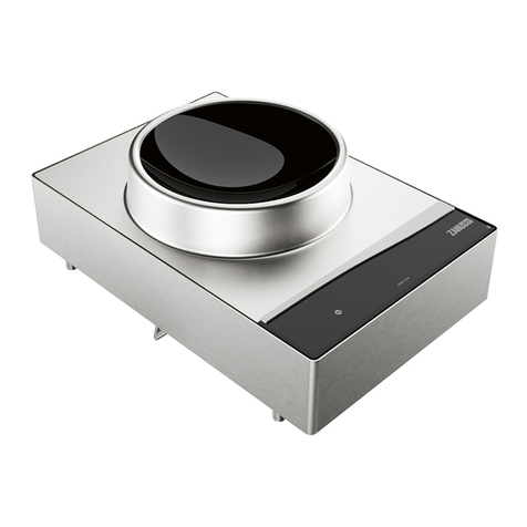
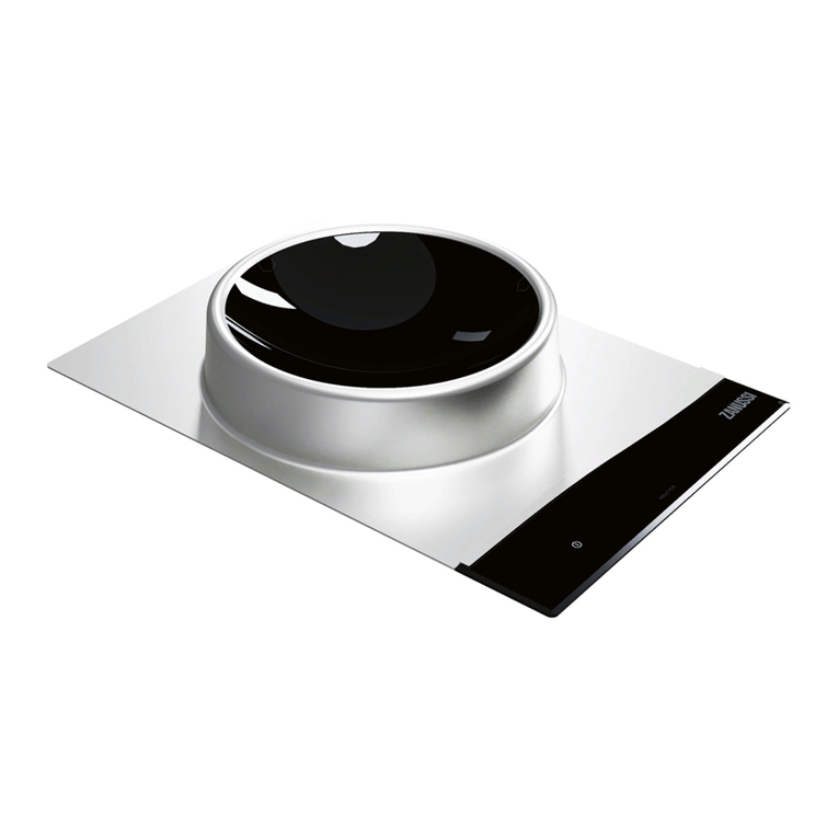
Nordcap ZANUSSI IWOKEC-3P / 1ZT User manual

Service Manual
Wok Induction IWOKEC-3P / 1ZT
[Art. 406600897]
2021-04

2
LIBERO LINE WOK INDUCTION
Document made by Product Care –Technical Training & Service –Vallenoncello PN/Italy
All the images and information of this document are property of ©Electrolux Professional Spa. This document
and all its contents cannot be copied or used, in part or entirely without the written authorization of Electrolux
Professional Spa.
REVISIONS UPDATE:
EDITION DESCRIPTION DATE
1 First edition of Service Manual APRIL. 2021
Foreword
The service manual (here in after Manual) provides the engineer with information necessary for correct
and safe care of the machine (here in after “machine“, “appliance“ or “unit”).
The following instructions are intended to maintain the machine performance and to preventing injury to per-
sons and animals and damage to property due to improper operating procedures.
All persons involved in machine transport, installation, commissioning and maintenance, repair and disassem-
bly must refer to the content of this manual before carrying out the various operations. This, in order to avoid
wrong and improper actions that could compromise the machine's integrity or endanger people.
If, after reading this manual, there are still doubts regarding machine use, do not hesitate to contact the Man-
ufacturer or the Customer Care to receive prompt and precise assistance for better operation and maximum
efficiency of the machine. During all stages of machine assessment, always respect the current regulations on
safety, work hygiene and environmental protection. It is the user's responsibility to make sure the machine is
started and operated only in optimum conditions of safety for people, animals and property.
IMPORTANT
•The manufacturer declines any liability for operations carried out on the appliance without respecting the
instructions given in this manual as well as for operations carried out by the user without respecting the
instructions given in the user manual.
•The manufacturer reserves the right to modify the appliances presented in this publication without notice;
manufacturer’s relevant technical bulletins should be used as integration(s)/addendum(s).
•No part of this manual may be reproduced without the consent of the manufacturer
•This manual is available in digital format by:
contacting the reference customer care;
downloading the latest and up to date manual/technical bulletin(s) on the web site:
“www.electrolux.com/professional“.
The manual must always be part of the documentation available when servicing the machine.
Doc. N. 059785XW00
Edition 1 –04-2021

3
LIBERO LINE WOK INDUCTION
MODELS COVERED BY THE SERVICE MANUAL
Refer also to § DATA PLATE (IDENTIFICATION STICKER)
Pnc
Model
Type
Frequency
Range
(Hz)
Rated Voltage
Rated
Input
(kW)
600880
1PH - WOK - DI
LLWS1D
50-60
220-240 V 1N~
3,5
600892
1PH - WOK - DI
LLWS1D
50-60
220-240 V 1N~
3,5
600904
1PH - WOK - DI
LLWS1D
50-60
220-240 V 1N~
3
600881
1PH - WOK - SA
LLWS1S
50-60
220-240 V 1N~
3,5
600893
1PH - WOK - SA
LLWS1S
50-60
220-240 V 1N~
3,5
600905
1PH - WOK - SA
LLWS1S
50-60
220-240 V 1N~
3
600884
3PH - WOK - DI
LLWS3D
50-60
380-415 V 3N~
5
600896
3PH - WOK - DI
LLWS3D
50-60
380-415 V 3N~
5
600885
3PH - WOK - SA
LLWS3S
50-60
380-415 V 3N~
5
600897
3PH - WOK - SA
LLWS3S
50-60
380-415 V 3N~
5
MODEL= 1PH / 3PH = Phase -SZ= Single Zone -DZ= Double Zone -SA= Stand Alone -DI= Drop In
TYPE= LL=Libero Line - W= Wok -S = Single zone 1/3= Phase - S/D= Stand Alone/ Drop In

4
LIBERO LINE WOK INDUCTION
INDEX
INDEX
1GENERAL INFORMATION.......................................................................................................................... 7
1.1 GENERAL INFORMATION ................................................................................................................. 7
1.2 SAFETY INFORMATION/PRECAUTIONS........................................................................................... 8
PERSONAL PROTECTION EQUIPMENT ................................................................................... 9
GENERAL INFORMATION........................................................................................................... 9
RESIDUAL RISKS ...................................................................................................................... 10
1.3 DATA PLATE (IDENTIFICATION STICKER)..................................................................................... 12
1.4 TECHNICAL DATA............................................................................................................................. 13
1.5 OVERALL DRAWINGS WITH MEASUREMENTS............................................................................. 14
1.6 CONTROL PANEL INTERFACES...................................................................................................... 16
1.7 DEFINITIONS/GLOSSARY ................................................................................................................ 17
2INSTALLATION AND COMMISSIONING ................................................................................................. 18
2.1 GENERAL INSTALLATION................................................................................................................ 18
UNPACKING AND POSITIONING THE EQUIPMENT............................................................... 18
ROOM REQUIREMENTS........................................................................................................... 18
LIMITATIONS.............................................................................................................................. 19
LIST OF POSSIBLE INSTALLATION SOLUTIONS................................................................... 19
2.1.4.1 ON BASE / REFRIGERATED BASE.................................................................................. 19
2.1.4.2 ON LIBERO POINT ............................................................................................................ 19
2.1.4.3 DROP IN............................................................................................................................. 20
2.1.4.3.1 DIMENSIONS & AIR REQUIREMENTS......................................................................... 21
APPLIANCE REQUIREMENTS.................................................................................................. 22
2.1.5.1 POWER (VOLTS)............................................................................................................... 22
2.1.5.2 AIR CIRCULATION ............................................................................................................ 22
2.1.5.3 APPLIANCE LOAD............................................................................................................. 22
2.2 ELECTRIC CONNECTION................................................................................................................. 23
HOW TO RECOGNIZE PHASE AND NEUTRAL....................................................................... 24
RESIDUAL CURRENT................................................................................................................ 24
2.4 FIRST START UP............................................................................................................................... 25
DAILY STARTUP........................................................................................................................ 25
2.5 COMMISSIONING.............................................................................................................................. 25
3USE OF APPLIANCE ................................................................................................................................ 26
3.1 OPERATING INSTRUCTIONS........................................................................................................... 26
3.2 CLEANING.......................................................................................................................................... 27
APPLIANCE & GLASS TOP SURFACE..................................................................................... 27
AIR FILTERS............................................................................................................................... 27
4DETAILED APPLIANCE AND COMPONENTS DESCRIPTION/FUNCTIONING.................................... 28
4.1 FUNCTIONAL / TECHNICAL DESCRIPTION.................................................................................... 28
4.2 EQUIPMENT FUNCTIONING ............................................................................................................ 28
4.3 AIR CIRCULATION............................................................................................................................. 28
4.4 COMPONENTS, DESCRIPTION/FUNCTIONING, APPLIANCE 3500W .......................................... 29

5
LIBERO LINE WOK INDUCTION
GENERATOR TESLA, POW ...................................................................................................... 29
VENTILATOR.............................................................................................................................. 30
AIR FILTER................................................................................................................................. 31
VENTILATOR (TANGENTIAL) M1 ............................................................................................. 31
USER INTERFACE, U.I .............................................................................................................. 32
COILS & TEMPERATURE SENSORS,...................................................................................... 33
4.5 COMPONENTS, DESCRIPTION/FUNCTIONING, APPLIANCE 5000W .......................................... 34
GENERATOR FOUCAULT - COILS & TEMPERATURE SENSOR........................................... 34
USER BOARD, U.I...................................................................................................................... 35
4.6 INDUCTION POTS, PRECAUTIONS................................................................................................. 35
4.7 PERFORMANCE................................................................................................................................ 36
POWER TABLE 1PH-WOK ........................................................................................................ 37
POWER TABLE 3PH-WOK ........................................................................................................ 37
4.8 ELECTRONIC BOARD....................................................................................................................... 38
SWITCHING ON / OFF............................................................................................................... 38
CUSTOMER MENU.................................................................................................................... 39
4.8.2.1 BUZZER MODE.................................................................................................................. 41
4.8.2.2 HOB2HOOD MODE ........................................................................................................... 42
4.8.2.3 ALARM HISTORY .............................................................................................................. 43
SERVICE MENU......................................................................................................................... 44
4.8.3.1 DEMO MODE ..................................................................................................................... 46
4.8.3.2 SI, SOFTWARE EDITION .................................................................................................. 47
4.8.3.3 S2, SELF-DIAGNOSTIC TEST OF GENERATORS OFF.................................................. 49
4.8.3.4 S3, SELF-DIAGNOSTIC TEST WITH GENERATORS ON ............................................... 52
4.8.3.5 S4, COOKING TOP COUPLING........................................................................................ 55
HOB TO HOOD (H2H, SPECIAL FUNCTION)........................................................................... 58
MANUAL FAN SPEED................................................................................................................ 58
AUTOMATIC FAN SPEED:......................................................................................................... 59
ALARMS...................................................................................................................................... 61
4.8.7.1 ALARM CODE LIST ........................................................................................................... 63
4.9 SOFTWARE UPDATE & WIFI............................................................................................................ 65
5TROUBLESHOOTING............................................................................................................................... 66
5.1 ALARM TROUBLESHOOTING .......................................................................................................... 66
6SERVICING THE APPLIANCE.................................................................................................................. 66
6.1 LIST OF NEEDED TOOLS................................................................................................................. 66
6.2 DISASSEMBLY/REASSEMBLE OF COMPONENTS........................................................................ 67
APPLIANCE CASING ................................................................................................................. 68
COMPONENTS APPLIANCE 3500W......................................................................................... 69
6.2.2.1 GENERATOR POB TESLA................................................................................................ 69
6.2.2.2 VENTILATOR ..................................................................................................................... 70
6.2.2.3 AIR FILTERS...................................................................................................................... 70
6.2.2.4 USER INTERFACE, U.I. &.VENTILATOR (TANGENTIAL) ............................................... 71
6.2.2.5 COILS................................................................................................................................. 72
6
LIBERO LINE WOK INDUCTION
COMPONENTS APPLIANCE 5000W......................................................................................... 72
6.2.3.1 GENERATOR FOUCAULT................................................................................................. 73
6.2.3.2 AIR FILTERS...................................................................................................................... 74
6.2.3.3 USER BOARD.................................................................................................................... 74

7
LIBERO LINE WOK INDUCTION
1 GENERAL INFORMATION
1.1 GENERAL INFORMATION
To ensure safe use of the machine and a proper understanding of the manual it is necessary to be familiar
with the terms and typographical conventions used in the documentation. The following symbols are used in
the manualto indicateand identifythe various types of hazards:
WARNING
Danger for the health and safety of operators.
WARNING
Danger of electrocution- dangerousvoltage.
CAUTION
Risk of damageto the machine or the product.
WARNING
Danger of magnetic fields.
IMPORTANT
Importantinstructionsor informationon the product
Read the instructions before using the appliance
Clarificationsand explanations
• Onlyspecializedpersonnelare authorizedto operate on the machine.
•This appliance must not be used by minors and adults with limited physical, sensory or mental
abilities or without adequate experience and knowledgeregardingits use.
–Do not let children play with the
appliance.
–Keep all packagingand detergentsaway from children.
–Cleaning and user maintenance shall not be made by children withoutsupervision.
•Do not store explosive substances, such as pressurized containers with flammablepropellant,in
this applianceor close to the appliance
•Do not remove, tamper with or make the machine “CE“ marking illegible.
•Refer to the data given on the machine’s data plate “CE“ marking for relations with the Manufacturer
(e.g. whenorderingspare parts,etc.).
• When scrappingthe machine,the “CE“ markingmustbe destroyed.

8
LIBERO LINE WOK INDUCTION
1.2 SAFETY INFORMATION/PRECAUTIONS
•Risksmainlyofamechanical,thermalandelectricalnatureexistinthe machine.Wherepossibletherisks
havebeenneutralized:
–directly,bymeansof adequatedesignsolutions.
–indirectlybyusingguards,protectionandsafetydevices.
•During maintenance several risks remain, as these could not be eliminated, and must be
neutralized by adopting specific measures and precautions.
•Do not carry out any checking, cleaning, repair or maintenance operations on moving
parts. Workers must be informed of this prohibitionbymeansof clearlyvisiblesigns.
•To guarantee machine efficiency and correct operation, periodical maintenancemust be carried
out accordingto the instructionsgiven in this manual.
•Make sure to periodically check correct operation of all the safety devices and the insulationof
electricalcables,whichmustbereplaced if damaged.
•Extraordinary machine maintenance operations must only be carried out by specialized Technicians
provided with all the appropriate personal protection equipment (safety shoes, gloves, glasses,
overalls,etc.),tools,utensilsandancillarymeans.
•Never operate the machine,removing,modifyingor tampering with the guards, protection or safety de-
vices.
•Before carryingout any operationon the machine,always consult the manual which gives the correct
procedures and contains important informationon safety.

9
LIBERO LINE WOK INDUCTION
PERSONAL PROTECTION EQUIPMENT
Summarytable of the Personal Protection Equipment (PPE) to be used during the various stages of the ma-
chine's service life.
Stage
Protective
garments
Safety
footwear
Gloves
Glasses
Safety
helmet
Transport
—
●
○
—
○
Handling
—
●
○
—
—
Unpacking
—
●
●
—
—
Installation
—
●
●
2
●
—
Normaluse
●
●
●
1
○
—
Adjustments
○
●
○
○
—
Routinecleaning
○
●
●
1 or 2
○
—
Extraordinary
cleaning
○
●
●
1 or 2
○
—
Maintenance
○
●
○
○
—
Dismantling
○
●
○
○
—
Scrapping
●
●
●
●
—
Key:
●
PPE REQUIRED
○
PPE AVAILABLEOR TO BE USED IF NECESSARY
—
PPE NOT REQUIRED
1. During these operations, the worn gloves must be heatproof to protect hands from contact with
hot food or hot parts of the appliance and/or when removing hot items from
it.
Failure to use the
personal protection equipment byoperators, specialized personnel or users can involve exposure
to chemical risk and possible damage
to
health (depending on the
model).
2. During these operations, the worn gloves must be cut-resistant. Failure to use the personal pro-
tection equipment by operators, specialized personnel or users can involve exposure to damage
to
health (depending on the
model).
GENERAL INFORMATION
•The machines are provided with electric and/or mechanical safety devices for protecting workers
and the machine itself. Therefore, the user must not remove or tamper with such devices. The Manufacturer
declinesanyliabilityfor damagedue to tamperingor theirnon-use.
•Never operate the machine,removing,modifyingor tampering with the guards, protection or safety de-
vices.
•Donotmakeanymodificationsto thepartssuppliedwiththeappliance.
•Several illustrations in the manual show the machine, or parts of it, without guards or with guards
removed. This is purely for explanatory purposes. Do not use the machine without the guards or with the
protectiondevicesdeactivated.
•Do not remove, tamper with or make illegible the safety, danger and instruction signs and labels on
the machine.

10
LIBERO LINE WOK INDUCTION
•Air recirculation must take into account the air necessary for combustion, 2 m³/h/kW of
gas power, and also the "well-being" of personsworkingin the kitchen.
•Inadequateventilationcausesasphyxia.Donotobstructthe ventilation system in the place where this
appliance is installed. Do not obstruct the vents or ducts of this or other appliances.
•Placeemergencytelephonenumbersin a visibleposition.
•Themeasuredsoundlevel emitted“A“ doesnot exceed 70 dB (“A“).
•Turnthe applianceoff in caseof faultor poor operation.
•Do not use products (even if diluted) containing chlorine (sodium hypochlorite,hydrochloricor
muriatic acid, etc.) to clean the appliance or the floor under it.
•Donotusemetaltoolstocleansteelparts(wirebrushesorScotchBrite typescouringpads).
•Donotallowoilorgreasetocomeintocontactwithplasticparts.Donot allowdirt,fat, foodorotherresidu-
alsto form depositson the appliance.
•Do not spraywateror usesteam to clean the equipment.
•Do not store or use gasoline or other flammable vapors, liquids or items in the vicinityof thisor any
other appliance.
•Do not spray aerosols in the vicinity of this appliance while it is in operation.
•Nevercheckfor leakswith an open flame.
RESIDUAL RISKS
•The machine has several risks that were not completely eliminated fromadesignstandpointor with
theinstallationof adequateprotection devices. Nevertheless, through this manual the Manufacturer has taken
steps to inform operators of such risks, carefully indicating the
personal protection equipment to be used by them. Sufficient spaces are provided for during the machine
installationstages in order to limit these risks.
To preserve these conditions, the areas around the machine must alwaysbe:
–kept freeof obstacles(e.g.ladders,tools,containers,boxes,etc.);
–clean and dry;
–well lit.
For the Customer's complete information, the residual risks remaining on the machine are indicated below:
such actions are deemed improperand thereforestrictlyforbidden.
Residual risk
Description of hazardous situation
Slippingor falling
The operatorcanslip due to wateror dirt on the floor
Burns/abrasions(e.g. heatingelements)
Theoperatordeliberatelyor unintentionallytouchessome compo-
nentsinside the machinewithout using protectivegloves
Electrocution
Contact with live parts during maintenance operationscarried out
with the electricalpanelpowered
Sudden closing of the lid/ door/oven door (if pre-
sent, dependingon
the
appliancetype)
The operator for normal machine use could suddenlyand deliber-
atelyclosethe lid/door/ovendoor(ifpresent,depending ontheap-
pliancetype)
Tippingof loads
Whenhandlingthe machineorthe packingcontainingit, using un-
suitable liftingsystemsor accessoriesor withthe loadunbalanced
Mechanicalsafetycharacteristics,hazards
•The appliance does not have sharp edges or protruding parts. The guardsforthemovingandlive
partsarefixedtothecabinetwithscrews, to prevent accidentalaccess.
Protectiondevicesinstalledon themachine
•The guardsonthe machineare:
–fixed guards
(e.
g. casings, covers, side panels, etc.), fixed to the machineand/orframe with
screwsor quick-releaseconnectorsthat can only beremovedor openedwithtools

11
LIBERO LINE WOK INDUCTION
Safety signs to be placed near the machine area
Prohibition
Meaning
do not remove the safety devices
do not use water to extinguish fires (placed on electri-
calparts)
Keep the area around the appliance clear and free
from combustible materials. Do not keep flammable
materialsin the vicinityof the appliance
Installthe appliancein a well-ventilatedplaceto avoid
the creation of dangerous mixtures of unburnt gases
in the same room
Danger
Meaning
danger of burns
dangerofelectrocution(shownonelectrical partswith
indicationof voltage)
risk of electromagneticfields
Access forbidden to wearers of electrical stimulator
(pacemakers)
End of use
When the appliance is no longer to be used, make it unusable by removing the mains power supply
wiring.

12
LIBERO LINE WOK INDUCTION
1.3 DATA PLATE (IDENTIFICATION STICKER)
The identification sticker is located on the bottom of the appliance. The meaning of the various information is
listed below:
EXAMPLE PICTURE !
SERIAL NUMBER (PRODUCTION
DATE) is necessary to find the correct
spare part or to ask tech. support.
EXAMPLE : Serial Number
114 2 0001
PNC
SER
EXAMPLE : TYPE
LL FT S 1 S

13
LIBERO LINE WOK INDUCTION
1.4 TECHNICAL DATA
Induction Wok
Type
LLWS1S
LLWS1D
LLWS3S
LLWS3D
Appliance description
Single Zone
Single Zone (UK)
Single Zone
Power supply voltage
V
220 –240
380 —415
Frequency
Hz.
50 –60
50 –60
Phases
Nr.
1N~
3~
Induction Wok
Type
LLWS1S
LLWS1D
LLWS3S
LLWS3D
Appliance description
Single Zone
Single Zone (UK)
Single Zone
Max current
A
16
13
7
Max total power
kW
3.5
3
5
Plug
Type
F (Schuko)
G
3N+PE 16A (IEC
60309)
TYPE= LL=Libero Line - W= Wok - S = Single zone 1/3= Phase - S/D= Stand Alone/ Drop In

14
LIBERO LINE WOK INDUCTION
1.5 OVERALL DRAWINGS WITH MEASUREMENTS
1PH / 3PH = Phase -SZ= Single Zone -DZ= Double Zone -SA= Stand Alone -DI= Drop In
1PH WOK SA
1PH WOK DI

15
LIBERO LINE WOK INDUCTION
3P WOK SA
3PH SZ DI

16
LIBERO LINE WOK INDUCTION
1.6 CONTROL PANEL INTERFACES
On/Off
(Printed on glass,
no backlight)
0
1
2
3
4
5
6
7
8
9
10
0
1
2
3
4
5
6
7
8
9
10
Timer management, zone 1
Power management, zone 1
Special function:
Key Lock
Zone 1 indicator
Special function:
Zone bridge
Zone 2 indicator
Timer management, zone 2
Special function:
Hob 2 Hood
Special function:
Connectivity services
Power management, zone 2
Special function:
Service utilities
ON /OFF Touchthe button: the griddle will turn on; a lamp test will occur, and the zone will then be ready
for temp regulation/setting.
LOCK It is possible to lock the control panel while the cookingzones are in operation, in order to prevent
accidental changes of the power level. To activate the function, press the button for three seconds; the corre-
sponding indicator turn red and blinks. To deactivate the function, touch the button again; the previously set
power level lightsup.
COOKING ZONES Front, Rear
POWER MANAGMENT the power output regulation can be
set by pressing the sliding bar or pressing on the “plus / minus”
l
TIMER DISPLAY
MERGED ZONES MODE Pressing the button the cooking zones will be merged and will be operable
through the left side hand touch panel only.

17
LIBERO LINE WOK INDUCTION
HOOD TO HOB (only with coupled Libero Point appliances) This is an advanced automatic function
that connects the hob to the Libero Point’s hood. Both the hob and the hood have an infrared signal commu-
nicator. The fan speed is automatically set based on the mode settings and the temperature of the hottest pan
on the hob. It is also possible to operate the fan from the hob manually pressing one to four times the button.
WIRLESS to be implemented.
1.7 DEFINITIONS/GLOSSARY
POW Induction Power Board. Sometimes referred also as “Hob Control” (HC) or “POB”
HC Hob Control, sometimes referred also as “Power Board” (POW).
TESLA Single-phase, Double generator, 3500W Induction Power Board.
FOUCAULT 3-phase, Single generator, 5000W Induction Power Board.
UI User Interface
HUI Hob User Interface
ROADRUNNER User Interface
PD or HPD Hob Pot Detection. A circuit, normally embedded in a POW, able to detect pot presence over
a coil.
HOB Induction Hob cooking appliance
WOK Induction WOK cooking appliance
FRY Induction Fry Top cooking appliance
SZ Single Zone (cooking appliance)
DZ Double Zone (cooking appliance)
SA Stand Alone
DI Drop In
1PH Single-phase power supply line
3PH 3-phase power supply line
MACS Mayor Appliance Communication System. A communication protocol used in Electrolux commercial
appliances.
HCS Hob Communication System protocol. A MACS-based protocol variant, especially dedicated to Hob
appliances.
DAAS Data Acquisition protocol. A MACS-based protocol variant, especially dedicated to exchange raw data
between electronic devices/boards.
APD Disconnection relay. Power relay, belonging to POW circuits that supplies power to the induction
circuits.
SW Software
HW Hardware
§= chapter / paragraph
MACHINE or “appliance“ or “unit”

18
LIBERO LINE WOK INDUCTION
2 INSTALLATION AND COMMISSIONING
2.1 GENERAL INSTALLATION
All the non-standard or out-of-standard situations should be reported on the commissioning form and duly
documented for future reference. The documentation available on the web sites (PRIDE-SERVICE PORTAL-
AGELUX etc..) In case of any doubt, refer to your local country customer care.
UNPACKING AND POSITIONING THE EQUIPMENT
ROOM REQUIREMENTS
To guarantee continuous operation,the room temperature range must be between 5°C and 40°C.
Outdoor functioning is strictly allowed only if the machine can be protected against any conditions being out of
the above temperature range and against any atmospheric agents.
On a hot cupboard base take precaution to install a baffle for preventing hot air to reach the oven fresh air
intake; this could create malfunctioning.
High room humidity may cause water to condensate on electric components hence causing short circuit.
WARNING / CAUTION !
Before any operation on the machine read Chapter SAFETY INFOR-
MATION/PRECAUTIONS. We recommend for any phase involving the removal of
the packaging to use cut-resistant gloves

19
LIBERO LINE WOK INDUCTION
LIMITATIONS
Induction appliances: to guarantee continuous operation at maximum power, the roomtemperature must
be below 40℃.
Drop in appliances have air intake limitations, please refer to § AIR REQUIREMENTS
LIST OF POSSIBLE INSTALLATION SOLUTIONS
Hereinafter, the instructions for the main installation possibilities. The different accessories have a dedicated
Installation Manual; please refer also to these documents provided with the accessories or available on PRIDE.
2.1.4.1 ON BASE /REFRIGERATED BASE
All Stand-alone appliances can be fixed onto bases.
2.1.4.2 ON LIBERO POINT
The Stand-alone appliances can be installed into the libero point

20
LIBERO LINE WOK INDUCTION
2.1.4.3 DROP IN
All appliances, except fry tops, are available with a specific PNC code as “drop in “ D.I., model.
Example picture of a D.I HOB.
1-Apply a sponge gasket type to the top surface. We recommend to not use silicone , this because it could
complicate any future extraction.
2-The fixing assembly can be inserted into the three different precut slots (1,2,3) depending on the thickness
of the top.
3- Fixing assembly installed
4- Tighten the screw to blocking the appliance into place
5- End result
Pictures are examples for installation purposes.
NOTE !
The sponge gasket, fixing assembly and air conveyor are not supplied with the drop-in appliance,
they are accessories and must be ordered separately.
This manual suits for next models
19
Table of contents
Other Nordcap Kitchen Appliance manuals

Nordcap
Nordcap ZANUSSI IWOKEC-1ZT User manual

Nordcap
Nordcap MORETTI FORNI iRoll iPs 33 User manual

Nordcap
Nordcap ZANUSSI IGEC-1P User manual

Nordcap
Nordcap KU 407-G User manual

Nordcap
Nordcap WK275-2 User manual

Nordcap
Nordcap Moretti Forni iDeckSeries User manual

Nordcap
Nordcap Zanussi IWOKEC-3P / 1ZDI User manual

Nordcap
Nordcap VINO 470 User manual

Nordcap
Nordcap DROP IN User manual

Nordcap
Nordcap 477600471 User manual