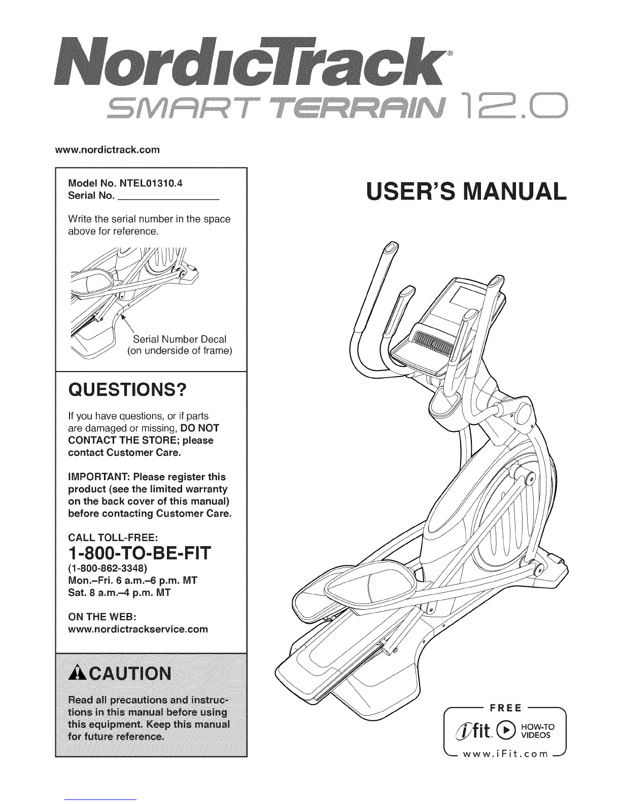
NordicTrack Smart Terrain 12.0 NTEL01310.4 User manual
Other NordicTrack Elliptical Trainer manuals

NordicTrack
NordicTrack E 11.5 Elliptical Quick start guide

NordicTrack
NordicTrack E 4.1 NTEVEL75012.0 User manual

NordicTrack
NordicTrack E 8.0 Elliptical User manual

NordicTrack
NordicTrack NEL09940 User manual

NordicTrack
NordicTrack NTEL05011.6 User manual

NordicTrack
NordicTrack Vgr 940 Operating and maintenance manual

NordicTrack
NordicTrack E9.5 23949.0 User manual

NordicTrack
NordicTrack E 11.6 Elliptical Quick start guide

NordicTrack
NordicTrack Xlt 1200 Elliptcal Quick start guide

NordicTrack
NordicTrack NTEL7906.4 User manual

NordicTrack
NordicTrack SE 3i User manual

NordicTrack
NordicTrack 831.283530 User manual

NordicTrack
NordicTrack Cxt 950 Elliptical User manual

NordicTrack
NordicTrack EX 1000 NTEL4255.1 User manual

NordicTrack
NordicTrack E 9.5 User manual

NordicTrack
NordicTrack E4.2 Elliptical Setup guide

NordicTrack
NordicTrack NTEL08991 User manual

NordicTrack
NordicTrack NTEL06011.0 User manual

NordicTrack
NordicTrack E 11.5 Elliptical Operating and maintenance manual

NordicTrack
NordicTrack SE 5i User manual


Popular Elliptical Trainer manuals by other brands


Bonn Germany
Bonn Germany Concept 2.2 user manual

Precor
Precor Resolute RSL 620 Assembly guide

Vision Fitness
Vision Fitness X6600iNetTV Assembly guide

Matrix
Matrix MX-A5x owner's manual

SportsArt Fitness
SportsArt Fitness ECO-NATURAL Elite E874 owner's manual

Sears
Sears FREE SPIRIT C249 30737 0 owner's manual