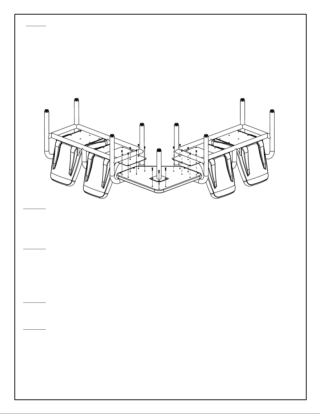
Step 4:
Attach the table top to the mounting plate, by hand starting the 12, 5/16” x 1” Torx
Screws. If you are installing a bolt down version, proceed to step 6. If you are
installing a model with adjustable glides, tighten the screws with the wrench
provided, and then adjust the level of the table by turning the glide.
Step 5:
For bolt down versions, once the 12 screws to mount the table have been hand
started, check for and adjust the level of the table by turning the bolt down tabs
on the table leg. Once the table and the seating units are level or the bolt down
tabs have been placed in the desired location, mark the position on the floor for
each of the concrete anchors. Remove the table and set aside. Move the 2
seating units out of the way to facilitate drilling the holes for the concrete anchors.
Step 6:
Drill a 2 ½ ” deep hole into the floor at each marking. Remove the concrete dust
from in and around the holes.
Step 7:
With the nut/washer assembly partially threaded onto each anchor, and using a
rubber mallet, hammer each anchor until it is secure in the hole. Remove the
nut/washer assembly and place the seating units and table top with table leg into
position. Attach the table top to the mounting bracket and tighten each screw
using the provided wrench. Once table top has been attached, secure the unit to
the concrete anchor by tightening the nut/washer assembly. (Tightening not only
secures table to floor, but also allows concrete anchor to expand and secure itself
in place.)
Step 3:
Each mounting bracket is marked with an “L” or “R”. The letter designation indicates
which side of the BEAM SEATING UNIT the bracket is to be mounted to. Brackets with an
“L” are to be mounted on the left end of a Beam Seating unit. Brackets with an “R” are to
be mounted on the right end of a Beam Seating unit. Slide the table mounting bracket
through the side of the Beam Seating unit. Position the table mounting plate so that the
plate is located underneath the steel plate that the seat is attached to. Attach each
table plate by hand starting the 6, 5/16” x 5/8” button head screws, through the table
plate and into the seat. Once all 6 screws have been started, tighten with the wrench
provided. Position each seating unit in the desired location.
Rev. B - 9/22/14
091-623
Page 2 of 2


