manuals.online logo
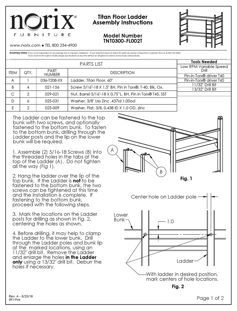
Brands
  1. Home
  2. •
  3. Brands
  4. •
  5. norix
  6. •
  7. Indoor Furnishing
  8. •
  9. norix Prodigy PRD700 User manual

norix Prodigy PRD700 User manual

Drill Guide, Pin (1)
011-063
5/8" Drill Bit (1)
029-944
Shim (4)
060-197
Screw, 5/16-18 X 5/8" L, BH (2)
021-118
Ball Lock Pin (2)
002-027
Guide Tube (2)
029-941
Pin Extractor Tool (1)
011-066
Concrete Anchor,
5/16" X 2" L (4)
024-024
Floor Anchor Bracket (2)
011-058
Anchor Hook, Left (1)
011-067
Anchor Hook, Right (1)
011-068
Anchor Tab, Straight (2)
011-059
Important Note: For a successful installation, careful and accurate
layout of the anchor brackets is a must. Read through the
instructions first and familiarize yourself with all of the steps. If you
have any questions, please call Norix Customer Care before
proceeding. Norix is not responsible for damage to components
due to improper installation.
Security Caulk is highly recommended to help seal gaps and
secure the furniture in place. Apply caulk to clean surfaces.
Anchor hardware:
Please familiarize yourself with the anchoring components as shown below.
If any components are missing, contact Norix Customer Care before proceeding.
Patents Pending
Parts List
ITEM
QTY.
PART NUMBER
DESCRIPTION
A
1
XXX XXX
Tools Needed
Low RPM Variable Speed Drill
Hammer Drill
5/16" masonry drill bit
Pin-in-Torx® Driver Bit T-40 (provided)
5/8" Drill Bit (provided)
Rev. B - 10/30/20
091-994
Page 1 of 9
www.norix.com ● TEL 800 234-4900
Assembly Notes:
Norix is not responsible for any damage due to improper installation. If your shipment does not match the parts list, please contact Norix Customer Service at 800-234-4900.
Norix reserves the right to modify design specifications at any time without an obligation to owners of previously sold products.
___________________________________________________________________________________________________________________________________________________________________________________________________
Prodigy Open Chest
Assembly Instructions
Model Number
PRD700
Molded line
on Chest
First line to draw
Second line to draw
Connect the two "T"s
using a chalk line
or straight edge
Mid-wall installation:
Note: In a mid-wall installation, the Left and Right Anchor
Hooks will not be used.
Both Ball Lock Pins and Guide Tubes
will
be used.
1.
Marking the Location
Place the Open Chest on the floor in an upright position in
the location where it is to be installed.
2. Mark a line on the floor along the
sides
of the Open
Chest, toward the center.
3. Locate the molded line at the center of each side, and
mark the floor at this location, perpendicular to the first
line. When finished marking, you will have what looks like a
letter "T" on each side.
4. Move the Open Chest aside.
5. Using a straight edge or chalk line, mark a line down the
center, by connecting the bases of the two "T"s that were
drawn in step 3.
Open Chest
open areas
The procedure for a
corner installation
is different from a
mid-wall installation
. These will be shown separately. See
page 6 for corner Installation.
Page 2 of 9
Rev. B - 10/30/20
091-994
3"
Centerline
Align vertical face
with inward line
Mark (4) drill locations
for Concrete Wedge Anchors
M
Drill Guide
Molded line is
centered in hole
6. Carefully measure 3" inward from the first line
and mark a second line. Repeat on the other side.
7. Place Floor Anchor Bracket with holes centered on
centerline as shown, and vertical face aligned with
the line as shown.
Mark (2) holes on floor for Concrete Wedge Anchors.
Repeat on the other side. When (4) drilling locations
have been marked on the floor, set Brackets aside.
8.
Install Floor Anchors and Brackets
If floor anchors other than the provided Concrete
Wedge Anchors are to be used, consult the
manufacturer for proper installation.
If the provided Concrete Wedge Anchors are to be
used, drill (4) 5/16" dia. holes a minimum of 1" deep
into the floor at the locations where previously
marked.
Vacuum debris from the holes.
Place the (2) Brackets back into their locations as
shown and install the Concrete Wedge Anchors,
securing the Hex Nuts tightly to the Brackets. Ensure
that the brackets are still aligned with the centerline
and the vertical face is still aligned with the 3" mark.
Make adjustments if necessary.
It is critical that these
brackets are installed inline and in the correct
position.
The provided Shims can be used to help
level the brackets.
9.
Drill Holes and Install Brackets Onto Open Chest
To drill the holes and install brackets, it is easiest if the
Chest is inverted. Place padding on the floor to
protect the Chest from scratches.
Wear protective gloves when drilling holes, in case of
an accidental slip.
Place the Drill Guide on the Open Chest so that the
molded line is centered in the diamond shaped hole
in the Drill Guide as shown. The Drill Guide may be
held by hand, or clamped in place with a padded C-
clamp if necessary.
It is important to drill the holes accurately in the
correct position, centered and in line with the molded
line.
Using the provided 5/8" brad-point drill bit, drill through
the Chest. Drill carefully, and don't force the bit. The
Guide will help drill a hole that is
perpendicular
to the
outer face of the Chest.
Repeat drilling a hole on the other side.
3"
3"
Make new lines
3'' inward
Page 3 of 9
Rev. B - 10/30/20
091-994
B
N
Straight Anchor Tab
5/16" X 5/8" L Screw
Guide Tube
10.
Install Anchor Tabs on the Open Chest
Install (2) Straight Anchor Tabs where shown, using
(2) 5/16" Screws.
11.
Install Guide Tube
Insert the Guide Tubes into the drilled hole on
each side.
Page 4 of 9
Rev. B - 10/30/20
091-994
Pin Extractor Tool
Ball Lock Pin
E
F
Ball Lock Pin Installed
Outer surface of Chest
CC
WALL
Floor Bracket
Anchor Tab
PP
WALL
Tab engaged
under Floor Bracket
12.
Set Open Chest in Place
Turn the Open Chest upright
and position in place over the
Floor Brackets.
Slide the Chest to engage the
Anchor Tabs with the Floor
Brackets.
13.
Install the Ball Lock Pins
Thread the Pin Extractor Tool into
one of the Pins until it is almost all
the way in. This will retract the two
ball bearings at the end of the pin.
Insert the Pin into the Guide Tube
at one end until the Head of the
Pin is below the outer surface of
the Open Chest.
Unscrew the Tool from the Pin.
The Pin is now locked in place.
Repeat for the 2nd Lock Pin.
Installation is complete.
Page 5 of 9
Rev. B - 10/30/20
091-994
Molded line
on Chest
First line to draw
Second line to draw
Corner Installation:
1.
Marking the Location
Place the Open Chest on the floor in an upright
position in the corner location where it is to be installed.
2. Mark a line on the floor along the exposed
side
of
the Chest, toward the center.
3. Locate the molded line at the center of the
exposed side, and mark the floor at this location,
perpendicular to the first line. When finished marking,
you will have what looks like a letter "T" on the floor.
4. Move the Chest aside.
5. Measure the width (from front to back) of the Chest
on the side that goes in the corner. Divide this number
in half. Measure out from the corner, and make a mark
on the floor at this dimension.
6. Using a straight edge or chalk line, mark a line down
the center, by connecting the base of the "T" and the
line previously drawn.
Half the width
(front to back)
of Chest
Connect the "T"
and the line from
Step 5 using a
chalk line or
straight edge.
Page 6 of 9
Rev. B - 10/30/20
091-994
3"
Align vertical face
with inward line
Center bracket
hole on intersection
3"
4
3
4
"
7. On the side that will be exposed, carefully
measure 3" inward from the first line
and mark a second line.
On the corner side, measure 4-3/4" from the
wall and draw a second line.
Exposed end: 3"
Corner end, 4-3/4"
8. Place the Floor Anchor Bracket so that the
holes are centered on the centerline as
shown, and the vertical face is aligned with
the line as shown.
Centerline
9. Place the corner end Floor Anchor Bracket
so that it is in the same direction as the first
bracket, with the holes centered on the
centerline as shown. The hole closest to the
wall should be
centered on the intersection
of
the lines.
Mark the (4) drill locations for the anchors.
Page 7 of 9
Rev. B - 10/30/20
091-994
Wall end uses Hook Tab
Exposed end uses Straight Tab
10.
Install Floor Anchors and Brackets
If floor anchors other than the provided Concrete
Wedge Anchors are to be used, consult the
manufacturer for proper installation.
If the provided Concrete Wedge Anchors are to
be used, drill (4) 5/16" dia. holes a minimum of 1"
deep into the floor at the locations where
previously marked.
Vacuum debris from the holes.
Place the (2) Brackets back into their locations as
shown and install the Concrete Wedge Anchors,
securing the Hex Nuts tightly to the Brackets.
Ensure that the brackets are still aligned with the
centerline and the vertical face is still aligned with
the 3" mark. Make adjustments if necessary.
It is
critical that these brackets are installed inline and
in the correct position.
The provided Shims can
be used to help level the brackets.
11.
Drill Holes and Install Brackets Onto Open
Chest
Refer to page 3 and the section on
Drill Holes
and Install Brackets Onto Open Chest.
Using the Drill Guide, drill a hole in
only
the
exposed side of the Chest. Do not drill a hole in
the side that goes against the wall.
12.
Install Anchor Tabs on Open Chest
In a
corner installation
, the wall side of the
Chest will receive a Hook Anchor, and the
exposed side will receive a Straight
Anchor Tab. Use whichever hook that will
point to the closest wall. For further
clarification, see the illustration on page 9,
step 14.
Install the brackets using (2) 5/16" Screws.
Hook faces
closest wall
Page 8 of 9
Rev. B - 10/30/20
091-994
N
Guide Tube
G G
DD
Push Chest at an angle
to engage the Hook
first
Rotate the Chest to
engage the Straight Tab
14.
Set Chest in Place
Place the upright Chest over the
brackets and slide the Chest in place
at an angle, ensuring that the Hook
Tab engages the Floor Anchor Bracket
first. Once the back corner of the unit
touches the wall, the Chest can be
rotated into place, engaging the
Straight Tab with the 2nd Floor Anchor
Bracket.
13.
Install Guide Tube
Insert the Guide Tube into the drilled hole in the
side.
15.
Install the Ball Lock Pin
Refer to Page 5, Step 13, to install the
Ball Lock Pin into the Guide Tube to
secure the Chest in place.
Page 9 of 9
Rev. B - 10/30/20
091-994

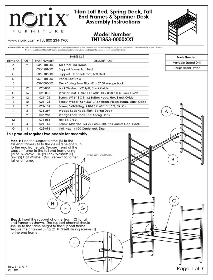
Other norix Indoor Furnishing manuals

norix ATN101-XXX.3 User manual

norix

norix ATN101-XXX.3 User manual

norix TNT0300-FL002T User manual

norix

norix TNT0300-FL002T User manual

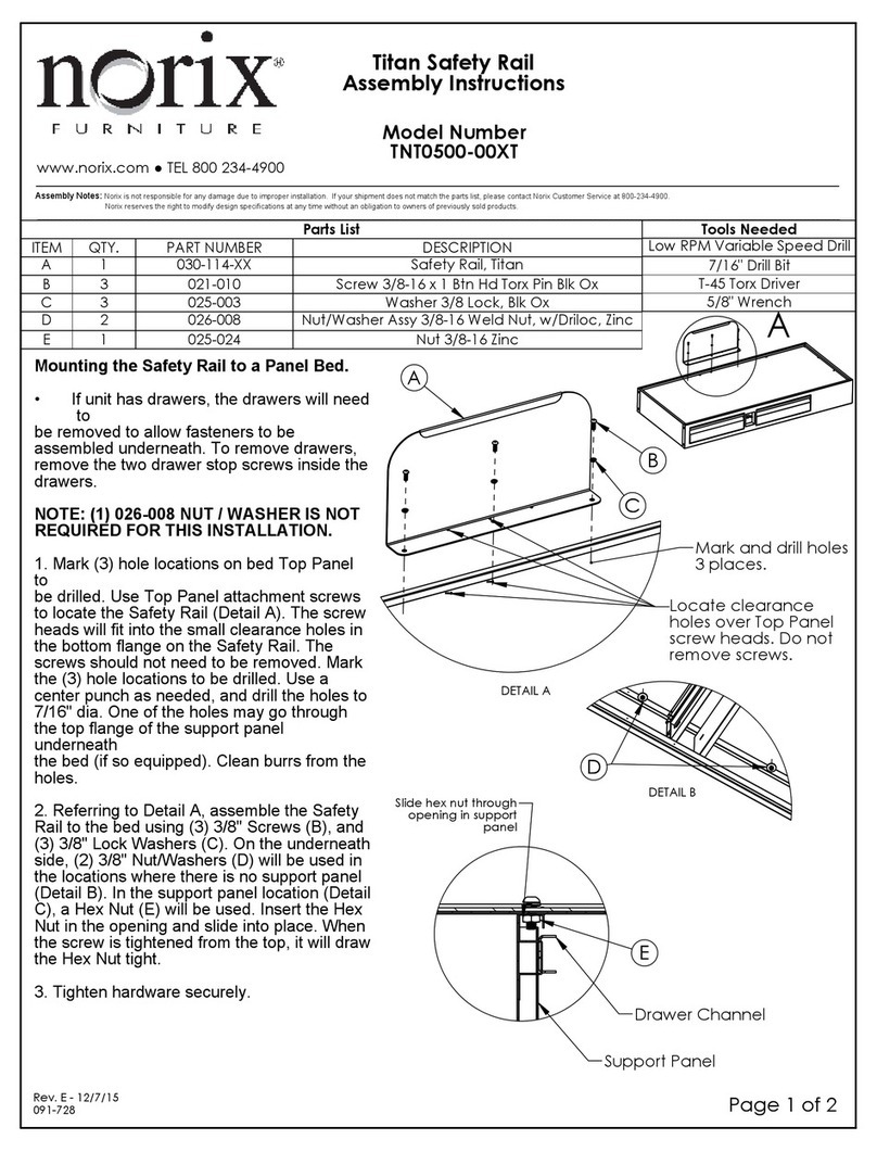
norix TNT0500-00XT User manual

norix

norix TNT0500-00XT User manual

norix Protege II Single PROT100 Series User manual

norix

norix Protege II Single PROT100 Series User manual

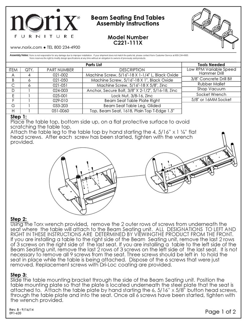
norix C221 Series User manual

norix

norix C221 Series User manual

norix TNT1853-0000XXT User manual

norix

norix TNT1853-0000XXT User manual

norix PRD100 User manual

norix

norix PRD100 User manual

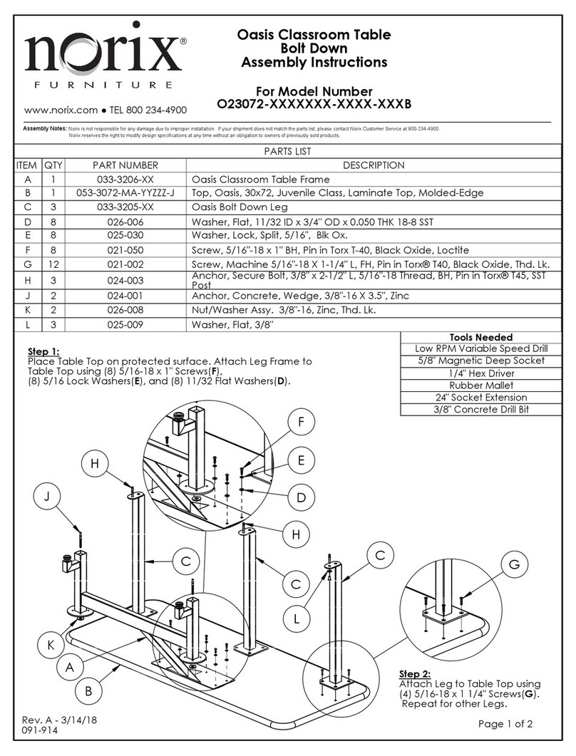
norix Oasis Classroom Table User manual

norix

norix Oasis Classroom Table User manual

norix TNT0802-BX1 User manual

norix

norix TNT0802-BX1 User manual

norix B510-2127 User manual

norix

norix B510-2127 User manual

norix Titan TNT1991 User manual

norix

norix Titan TNT1991 User manual

norix C221-111 Series User manual

norix

norix C221-111 Series User manual

norix Titan TNT1620-0L T Series User manual

norix

norix Titan TNT1620-0L T Series User manual

norix PRD240 User manual

norix

norix PRD240 User manual

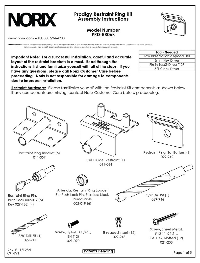
norix PRD-RR06K User manual

norix

norix PRD-RR06K User manual

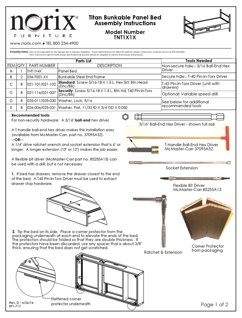
norix TNT1X1X User manual

norix

norix TNT1X1X User manual

Popular Indoor Furnishing manuals by other brands

Ondis24 Werkbank Bernd Plus Assembly instructions

Ondis24

Ondis24 Werkbank Bernd Plus Assembly instructions

Home Decorators Collection MANOR OAKS GC-11352-AAP Use and care guide

Home Decorators Collection

Home Decorators Collection MANOR OAKS GC-11352-AAP Use and care guide

Lifely Sven Series Assembly instruction

Lifely

Lifely Sven Series Assembly instruction

Coaster 300281 Assembly instructions

Coaster

Coaster 300281 Assembly instructions

Meblik Bookcase high 100 manual

Meblik

Meblik Bookcase high 100 manual

BDI CODE 7376 Assembly instructions

BDI

BDI CODE 7376 Assembly instructions

Safavieh Furniture FOX6501 quick start guide

Safavieh Furniture

Safavieh Furniture FOX6501 quick start guide

Interstuhl Büromöbel Goal operating instructions

Interstuhl Büromöbel

Interstuhl Büromöbel Goal operating instructions

Whalen VANITY WITH TOP WF30CVG Assembly instructions

Whalen

Whalen VANITY WITH TOP WF30CVG Assembly instructions

LAZBOY PowerReclineXR Series operating instructions

LAZBOY

LAZBOY PowerReclineXR Series operating instructions

Atlantic Furniture Bordeaux Headboard Assembly instructions

Atlantic Furniture

Atlantic Furniture Bordeaux Headboard Assembly instructions

Forte MQRK231 Assembling Instruction

Forte

Forte MQRK231 Assembling Instruction

Pressalit R8662 Mounting instruction

Pressalit

Pressalit R8662 Mounting instruction

MAZE ASCOT DELUXE Assembly instructions

MAZE

MAZE ASCOT DELUXE Assembly instructions

Mayline MAYTRIX LAN FURNITURE 90 DEGREES CORNER WORK... Assembly instructions

Mayline

Mayline MAYTRIX LAN FURNITURE 90 DEGREES CORNER WORK... Assembly instructions

Johanson STROLL 65 WITH WEELS manual

Johanson

Johanson STROLL 65 WITH WEELS manual

Next DORSET A77315 Assembly instructions

Next

Next DORSET A77315 Assembly instructions

Thomasville THMSVL36AVB Use and care guide

Thomasville

Thomasville THMSVL36AVB Use and care guide

manuals.online logo
manuals.online logoBrands
  • About & Mission
  • Contact us
  • Privacy Policy
  • Terms and Conditions

Copyright 2025 Manuals.Online. All Rights Reserved.