North-Vision Tech Elegant-1100 User manual

Multi-parameter Patient Monitor
Elegant-1100
User Manual
Version: 3.0
Issued by: Sara Lo Date: 7/20/2020
Reviewed by: Albert Huang Date: 7/20/2020
Document No: UM-PM1-201405-01
North-Vision Tech. Inc.
2460

I
This Manual is written and compiled in accordance with the IEC 60601-1(Medical electrical
equipment Part1: General requirements for safety),and MDD 93/42/EEC. It complies with both
international and enterprise standards and is also approved by the Food and Drug Administration,
Ministry of Health and Welfare. The Manual is written for the current Elegant-1100 Multi-parameter
Patient Monitor.
The Manual describes, in accordance with the Elegant-1100 Multi-parameter Patient Monitor’s
features and requirements, main structure, functions, specifications, correct methods for transportation,
installation, usage, operation, repair, maintenance and storage, etc. as well as the safety procedures
to protect both the user and equipment. Refer to the respective chapters for details.
The Manual is published in English and we have the ultimate right to explain the Manual. No part
of this manual may be photocopied, reproduced or translated into another language without the prior
written consent. We reserve the right to improve and amend it at any time without prior notice.
Amendments will however be published in a new edition of this manual.
All rights reserved.
Marks in the Manual:
Warnings: must be followed to avoid endangering the operator and the patient.
Notes: contains some important information and tips about operations and application.
Attentions: must be followed to avoid causing damage to the monitor.

User Manual for Multi-parameter Patient Monitor North-vision Tech. Inc.
II
Instructions to User
Dear Users, thank you very much for purchasing our product. Please read the following
pages very carefully before using this equipment.
Read these instructions carefully before using this monitor. These instructions describe
the operating procedures to be followed strictly. Failure to follow these instructions can cause
monitoring abnormity, equipment damage and personal injury. The manufacturer is NOT
responsible for the safety, reliability and performance issues and any monitoring abnormity,
personal injury and equipment damage due to user’s negligence of the operation instructions.
The manufacturer’s warranty service does not cover such faults.
WARNING
Do NOT operate this monitor in the circumstance where flammable gas or explosion
factor exists.
To ensure patient safety, do NOT place the monitor in any position that might cause it
to fall on patient.
The user must check that the equipment functions safely and ensure that it is in
proper working condition before being used.
The device connected to this monitor should be in accordance with IEC 60601-1.
Please shut down the monitor and remove sensors while during MRI scanning, or else
induced current could potentially cause burns. The monitor may affect the MRI image,
and the MRI unit may affect the accuracy of monitor measurements.
Although biocompatibility tests have been performed on all the applied parts, some
exceptional allergic patients may still have anaphylaxis. Do NOT apply to those who
suffer from anaphylaxis.
All the cables and rubber tubes of the applied parts should be kept away from the
patient’s cervix to prevent any possible suffocation of the patient.
All the parts of the monitor should NOT be replaced at will. If necessary, please use
the components provided by the manufacturer or those of the same model and
standards as the accessories along with the monitor which are provided by the same
factory, otherwise negative effects concerning safety and biocompatibility, etc. may
be caused.
If the monitor falls off accidentally, please do NOT operate it until its safety and

User Manual for Multi-parameter Patient Monitor North-vision Tech. Inc.
III
technical indexes have been carefully tested and positive testing results obtained.
Before maintenance, please switch off power.
This monitor is a professional medical device, can only be operated by trained
personnel with qualification.
Please peruse the relative content about the clinical restrictions and contraindication.
Dispose of the expired device and its accessory according to applicable local
regulations.
CONTRAINDICATIONS
It is contraindicated for use on active patients or for prolonged use.
ADVERSE REACTION
Continuous use of fingertip SpO2sensor may result in discomfort or pain, especially
for those patients with microcirculatory problem. It is recommended that the
sensor should NOT be applied to the same finger for over two hours.

User Manual for Multi-parameter Patient Monitor North-vision Tech. Inc.
IV
TABLE OF CONTENT
CHAPTER 1 OVERVIEW 1
1.1 FEATURES 1
1.2 PRODUCT NAME AND MODEL 2
1.3 DESCRIPTION AND INDICATION FOR USE 2
1.4 REQUIREMENT OF OPERATING ENVIRONMENT AND INSTALLATION 2
1.5 NORMAL WORKING ENVIRONMENT 2
1.6 IMPACT ON ENVIRONMENT AND RESOURCES 3
1.7 SAFETY 3
CHAPTER 2 THE OPERATION AND THE PATIENT MONITOR 4
2.1 OVERALL STRUCTURE AND WORKING THEORIES 4
2.2 COMPOSITION 4
CHAPTER 3 INSTALLATION AND CONNECTION 5
3.1 PANEL INTRODUCTION 5
3.1.1 Front Panel 5
3.1.2 Left and Right Side Panel 7
3.1.3 Back Panel 8
3.2 INSTALLATION 9
3.2.1 Opening the Box and Check 9
3.2.2 Connecting the AC Power Cable 9
3.2.3 Starting the Monitor 9
3.3 CONNECTION 10
3.3.1 ECG Connection 10
3.3.2 Blood Pressure Cuff Connection 11
3.3.3 To connect the SpO2 12
3.3.4 Battery Installation 13
3.3.5 Loading Printing Paper 13
CHAPTER 4 MONITORING SCREEN 15
4.1 MAIN SCREEN 15
4.1.1 Date and Time Setup 15
4.1.2 Screen Description 16
4.2 DISPLAY2 SCREEN 20
4.2.1 Viewing Screen 20
4.3 FREEZE AND ST ANALYSIS SCREEN 21
4.3.1 Screen Description 21
4.3.2 Operation Instruction 22
4.4 MODE SELECTION SCREEN 22
4.5 SPO2 DATA LIST SCREEN 23

User Manual for Multi-parameter Patient Monitor North-vision Tech. Inc.
V
4.5.1 Screen Description 23
4.6 TREND SCREEN 23
4.6.1 Screen Description 23
4.6.2 Operating Instructions 25
4.7 RECALL SCREEN 26
4.8 THE MENU SETUP SCREEN OF THE SYSTEM 28
4.8.1 Screen Description 28
4.8.2 System Parameter Settings 30
4.8.3 ECG Parameter Settings 30
4.8.4 NIBP Parameter Settings 31
4.8.5 SpO2 Parameter Settings 32
4.8.6 Reset 32
4.9 COLOR SETTINGS SCREEN 32
4.10 FILE/PATIENT MANAGEMENT SCREEN 33
CHAPTER 5 TECHNICAL SPECIFICATIONS 34
5.1 ECG MONITORING 34
5.2 NIBP MONITORING 35
5.3 SPO2 MONITORING 35
5.4 PULSE RATE MONITORING 35
5.5 DATA RECORDING 35
5.6 OTHER TECHNICAL SPECIFICATIONS 35
5.7 CLASSIFICATION 35
5.8 DEFAULT ALARMING VALUES OF ALL PARAMETERS 36
CHAPTER 6 PACKAGING AND ACCESSORIES 37
6.1 PACKAGING 37
6.2 ACCESSORIES 37
CHAPTER 7 MONITORING PARAMETERS 38
7.1 MEASURING ECG 38
7.2 THE PRINCIPLE FOR MEASUREMENT OF THE BLOOD PRESSURE 39
7.2.1 Comparison between Blood Pressure Measuring Methods 39
7.3 MEASURING THE BLOOD PRESSURES 41
7.3.1 Operational Tips 41
7.3.2 Clinical Limitations 41
7.4 MEASURING THE PULSE OXYGEN SATURATION AND PULSE RATE 43
7.4.1 Operational Tips 43
7.4.2 Clinical Limitations 43
CHAPTER 8 MAINTENANCE 44

User Manual for Multi-parameter Patient Monitor North-vision Tech. Inc.
VI
8.1 PROTECTIVE MAINTENANCES 44
8.2 BATTERY MAINTENANCE 44
8.3 CLEANING, STERILIZATION AND DISINFECTION OF THE MONITOR 45
8.4 CLEANING, STERILIZATION AND DISINFECTION OF ACCESSORIES 45
8.5 STORAGE 46
8.6 TRANSPORTATION 46
CHAPTER 9 TROUBLESHOOTING 47
9.1 NO DISPLAY ON THE SCREEN 47
9.2 EXCESSIVE ECG SIGNAL INTERFERENCE OR THICK BASELINE 47
9.3 NO BLOOD PRESSURE AND PULSE OXYGEN MEASUREMENTS 47
9.4 SYSTEM ALARM 47
CHAPTER 10 APPENDIX 48
10.1 OTHER TERMS AND MESSAGES 48

User Manual for Patient Monitor
1
Chapter 1 Overview
1.1 Features
This monitoring system may be used to monitor patient’s ECG, non-invasive blood pressure (NIBP), pulse
oxygen saturation (SpO2), pulse rate and other physiological parameters.
10.4” high-resolution color LCD to display patient’s ECG waveform and SpO2 cubage waveform;
Abundant and friendly display interface, multifold ECG display screen:
Main monitoring screen: displays the information of all the waveforms and parameters visually.
Observing screen: heart rate value and SpO2 value display in big fonts, displays an ECG waveform
and a SpO2 cubage waveform at the same time.
Storage and recall of a list of 400 groups of NIBP measurement data, as well as heart rate and
SpO2/pulse rate when the measure of blood pressure is taken;
Nonvolatile 6hours of ECG data storage and recall;
High precision NIBP measuring module, good repeat capability;
Software and hardware-dual excess air pressure protection function;
Special SpO2 measuring device, which ensures the accuracy of SpO2 and pulse rate measures;
Unique file management, which enables recording, modifying, deleting and saving operation of
patient’s information.
Precise alarm system, different alarm events adopt different alarm degrees; 3 degrees visual and
audible alarm function;
Flexible high and low alarm limits setting function;
Resistance against defibrillator and electrosurgical knife interference; Cardiac pacemaker restraining
function enables to be used along with cardiac pacemaker;
Blood pressure may be measured in the mode of “adult/pediatric”, which may be selected via the
menu, to better suit the adult and pediatric patient;
Built-in printer (optional) to output waveforms and text;
Networking with the central station as a part of the central network;
Easy to Color-code and change the color of the font, background and waveforms if needed;
Battery power indicator, which enables near real-time battery power detection and displays the
battery power.

User Manual for Patient Monitor
2
1.2 Product Name and Model
Name: “North-vision”Multi-parameter patient monitor
Model: Elegant-1100
1.3 Description and Indication for use
1.3.1 Device Description
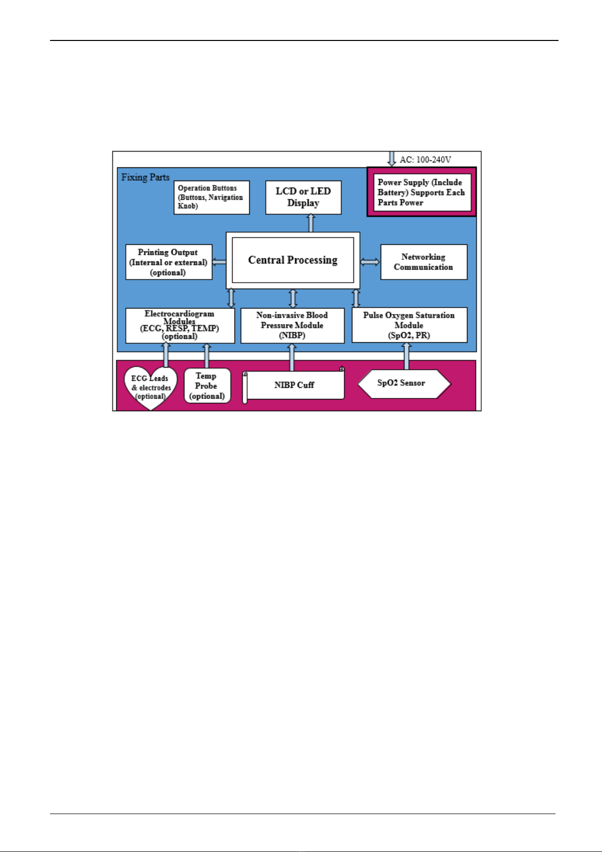
Elegant-1100 is intended to monitor, display and record physiological data to provide cardiac and
vital signs monitoring within a medical facility. It is modular designed patient Monitor, which can
monitor the patient’s Electrocardiograph (ECG) by measuring physical parameters with variety
modules. Also, It can measure non-invasive blood pressure (NIBP) including systolic, diastolic and
mean as well as detect the blood oxygen saturation (SpO2) and pulse rate (PR).
The accessories and the sensors will transfer the physical parameters into electrical signals,
which can be collected and amplified by the circuit in the device. After CPU analyzing and
calculating the parameters are displayed on the screen in a graphical representation and it can
record and/or print if necessary. The device may generate audible and/or visual alarm when a
measured rate falls outside preset limits.
1.3.2 Indication for use
North-vision Elegant-1100 of Multi-parameter Patient Monitor is intended to monitor, display and
record physiological signs of adult, pediatric patients. With the functions of near real-time
recording and displaying parameters ECG, heart rate, non-invasive blood pressure, blood oxygen
saturation and pulse rate, it allows comprehensive analysis of patient’s physiological conditions.
This apparatus is applicable for use in hospitals, clinics, and practitioner’s office. The operation
should be carried out by qualified professionals only.
1.4 Requirement of Operating Environment and Installation
1. This device should be situated in a place protected against direct sunlight, so as to prevent overheating
inside the equipment.
2. Do not use this device in an environment with toxic or inflammable gas.
3. This device should be fixed on a stand or flat platforms, so as to prevent possible shock.
4. Do not use with any equipment other than those expressly permitted in these instructions.
5. When using this device with electrosurgical equipment, the user (doctor or nurse) should pay attention to
the safety of patient.
6. Make sure that the equipotential grounding terminal is grounded correctly.
1.5 Normal Working Environment
1. Ambient temperature range: 10°C ~40°C
2. Relative humidity: ≤80%
3. Atmospheric pressure: 86kPa ~106kPa

User Manual for Patient Monitor
3
4. Power supply: a.c.100~240V
5. Power frequency: 50/60Hz
1.6 Impact on Environment and Resources
Low
1.7 Safety
a) Conform to IEC 60601-1, certified as Class II, with Type BF and CF applied parts.
b) Elegant-1100 Multi-parameter Patient Monitor can resist against defibrillator and electrosurgical
equipment interferences, and can detect and filter the pacemaker-generated signals;

User Manual for Patient Monitor
4
Chapter 2 The Operation and the Patient Monitor
2.1 Overall Structure and Working Theories
The overall structure of this monitor is shown as Fig.2.1.
Elegant-1100 patient monitor is a product of modular design. It performs its measurement of the
physiological parameter through different modules. There are four functional modules for the monitor: ECG
module, NIBP module, SpO2 module and Central Processing Unit (CPU) module.
1. ECG module collects heart rate through the ECG leads.
2. SpO2 module collects data for pulse rate, pulse oxygen saturation (SpO2) and SpO2 volume waveform via
the SpO2 probe.
3. NIBP module collects blood pressure data, including the diastolic, systolic and mean arterial pressure
through the NIBP cuff. The cuffs are sized for adult, pediatric. NIBP measure has three modes: adult,
and pediatric mode.
4. CPU module consists of main board, multi-function board, and the keyboard. The multi-function board
performs the data communication between the main board, ECG module, SpO2 module and NIBP
module.
2.2 Composition
1. The monitor consists of the main unit and the corresponding functional components (ECG leads,
non-invasive blood pressure cuff, and SpO2 probe).
2. The monitor has 4 measurement channels: ECG, NIBP channel, SpO2 and pulse channel.
3. The monitor has two output channels: networking communication port and printer.
4. Basic parameters include: heart rate, NIBP, SpO2, pulse ratre.

User Manual for Patient Monitor
5
Chapter 3 Installation and Connection
3.1 Panel Introduction
3.1.1 Front Panel
Figure 3.1 Elegant-1100 Front Panel
The patient monitor front panel is shown above:
1 Power switch
Press it to turn on the monitor, press it again to turn off the monitor.
2 ~: AC power indicator
When AC indicator is on, it means this device is using mains power supply.
3 : DC build-in battery indicator
When DC indicator is on, it means the battery is being used; when both of AC indicator and DC indicator light
are on, it means that this device is using mains power supply and the battery is being recharged.
4 LEAD switch
Click it to shift the ECG monitoring circulatory among Ⅰ, Ⅱ, Ⅲ, aVR, aVL, aVF, V and GND.
5 ALARM
Press this key to setup the alarm function.
In monitoring screen, press this key to set the alarm silent time. The time shows on the upper left corner. The
1 2 3 4 5 6 7 8 9 10
North-vision

User Manual for Patient Monitor
6
system starts count-down after the alarm silent time is set and will activate the alarm when the count-down
ends.
The alarm silence time has 4 settings: 2 min, 5 min, 10 min and 20 min, or in alarm.
6 FREEZE
Press this key to freeze ECG wave, or ECG, SpO2 based on the freezing settings in the system.
It also enters the ST segment manual analysis screen.
7 NIBP
Press this key to start NIBP measurement. Press it again to stop the measurement.
8 PRINT
Press this key to print different waveforms on different screens.
In the main screen, archive/file management screen, color setting screen, it prints the ECG waveform, SpO2
waveform.
In the NIBP data-listing screen, it prints the NIBP data list.
In the SpO2 data- listing screen, it prints the SpO2 data list.
In the Trend screen, it prints the system trend graph.
In the System menu, it prints the system parameter settings.
In the Recall screen, it prints the Recalled data list or prints current lead’s ECG waveform and Recalled
waveform.
9 DISP (Display)
Press this key to switch between initial monitoring screen and Observe Screen, and press it to return to the
main screen from other screens.
10 Navigation Knob
By rotating the navigation knob, the operator can choose the function and parameters. By pushing down and
releasing the knob, the operator can switch screen, confirm operations.
The majority of the operations of the monitor are performed by using navigation knob.
11 Alarm indicator

User Manual for Patient Monitor
7
3.1.2 Left and Right Side Panel
Figure 3.2 Left panel Figure 3.3 Right panel
The built-in printer is on the left panel as shown in Figure 3.2.
The right panel of the monitor hosts the patient cable and probe jacks, as shown in Figure 3.3.
1. NIBP - NIBP measuring cuff jack
2. SpO2 - SpO2 probe jack
3. ECG - ECG leads jack
4. Battery cover, remove the cover to install or change rechargeable battery. Factory default: two
rechargeable batteries (12V 2.3Ah); battery specification: FB 12V 2300mAh.
“TO AVOID BATTERY DAMAGE, ALWAYS REMOVE BATTERY(S) BEFORE SHIPPING OR STORAGE”
With Type BF applied part
With Type CF applied part and applicable during the defibrillator is used.
Caution! Please read the manual for details.

User Manual for Patient Monitor
8
3.1.3 Back Panel
Figure 3.4 Back panel
The back panel of the monitor includes the following
1. MONITOR: External monitor port
2. NET: Communication port which is used to network with central monitoring system
3. : Equipotential grounding port
4. FUSE 2 X T6.3A: Fuse holder; fuse specification: T6.3AL/250V Φ520mm
5. AC 100V~240V: Power supply socket
6. S/N: Serial Number
7. Nameplate

User Manual for Patient Monitor
9
3.2 Installation
3.2.1 Opening the Box and Check
1. Open the packaging, take out the monitor accessories from the box carefully and place it in a safe stable
and easy to watch position.
2. Open the users’ manual to sort the accessories according to the packing list.
Inspect the accessories for any mechanical damages
Check all the exposed leads and inserted accessories
Please contact the local dealer or our company in case of any problems. We are to offer you the best
solution for your satisfaction.
3.2.2 Connecting the AC Power Cable
Connecting procedures:
Make sure that the AC power supply is 100-240Vac, 50/60Hz.
Use the power cable prepared by the manufacturer. Insert one end of it to the power port of the
monitor and the other end to the grounded three-phase power jack.
Connect the monitor to the grounding port with the provided ground cable.
Caution: ensure that the monitor is grounded correctly.
The provided battery of the monitor must be recharged after transportation or storage. So if
the monitor is switch on without being connected to the AC power socket, it may not work
properly due to insufficient power supply.
3.2.3 Starting the Monitor
The system performs self-detection and enters initial display after switch on the monitor, and the orange
alarm indicator blinks to inform that the user can begin operating it.
Check all the applicable functions to make sure that the monitor works normally.
If the built-in battery is applied please recharge it after using the monitor to ensure sufficient power
storage.
Do not use the monitor to monitor the patient if there are indications of damage or reminders
of error. Please contact the local dealer or our company.
Start the monitor again 30 seconds later after it is switched off.

User Manual for Patient Monitor
10
3.3 Connection
3.3.1 ECG Connection
ECG measurement is to collect the ECG signal via the ECG electrodes. Electrode connects the patient and
the lead. The lead connects the monitor. The locations of the electrodes are very important for obtaining
accurate ECG signals.
1. Connect the cable to the right-panel connector marked with the ECG icon.
2. Select electrodes to be used. Use only one type of electrode on the same patient to avoid variations in
electrical resistance. For ECG monitoring, it is strongly recommended to use silver/silver chloride
electrodes. When dissimilar metals are used for different electrodes, the electrodes may be subject to
large offset potentials due to polarization. Using dissimilar metals may also increase recovery time after
defibrillation.
3. Prepare the electrode sites according to the electrode manufacture’s instructions.
The locations of the electrode are in the following Figure:
Figure 3.5 Locations of Electrodes
Note: If skin rash or other unusual symptoms develop, remove electrodes from patient.
4. After starting the monitor, if the electrodes become loose or disconnected during monitoring, the system
will display “LEAD OFF” on the screen to alarm the operator.
It might not display ECG wave with 3 leads. The 5 leads should be used to have
ECG wave.
5. The ECG leads and their corresponding locations are as follows:
Safety Instructions for ECG Monitoring

User Manual for Patient Monitor
11
Elegant-1100 Multi-parameter Patient Monitor can only be equipped with ECG leads provided by our
company; using ECG leads supplied by other companies may cause improper performance or poor
protection while using defibrillator.
Electric parts of electrodes, leads and cable are forbidden to contact any other conductive parts
(including ground).
Elegant-1100 Multi-parameter Patient Monitor can resist against defibrillator and electrosurgical unit.
Readings may be inaccurate for a short time after or during using defibrillator or electrosurgical unit.
Transient caused by cable circuitry blocks while monitoring may be similar to the near real heartbeat
waveform, as a result resistance heart rate alarm rings. If you put the electrodes and cable in proper
places according to this manual’s instructions and the instructions for using electrode, the chance of
this transient occurring will be decreased.
To the patient with pacemaker, due to that this device has been designed to provide resistance to
pacemaker signal interference, generally the pacemaker pulse is not counted in heart rate
measurement and calculation, but when the cycle time of pacemaker pulse is over 2ms, it may be
counted. In order to reduce this possibility, observe the ECG waveforms on the screen carefully and
do NOT rely entirely on the heart rate display and alarm system of this monitor when monitoring this
kind of patients.
Besides the improper connection with electrosurgical unit may cause burns, the monitor may be
damaged or arouse deviations of measurement. You can take some steps to avoid this situation, do
NOT use small ECG electrodes, choosing the position which is far away from the estimated Hertzian
waves route, using larger electrosurgical return electrodes and connecting with the patient properly.
ECG leads may be damaged while using defibrillator. If the leads are used again, please do the
functional check first.
3.3.2 Blood Pressure Cuff Connection
1. Connect the cable to the right-panel connector marked with the NIBP icon.
2. Select a cuff of appropriate size according to the age of the subject. Its width should be 2/3 of the length
of The upper arm. The cuff inflation part should be long enough to permit wrapping 50-80% of the limb
concerned. See the table below for the dimensions:
Note: The size of the cuff selected should suit the subjects while measuring.
Cuff Model
Arm Circumference
Cuff Width
Small-sized Pediatric Cuff
12cm ~ 19cm
11cm
Child Cuff
18cm ~ 26cm
8.4cm
Adult Cuff
25cm ~ 35cm
14cm
Large-sized Adult Cuff
33cm ~ 47cm
17.4cm
Prior to use of the cuff, empty the cuff until there is no residual air inside it to ensure accurate
measurement.
When putting on the cuff, unveil and wrap it around the upper arm evenly to appropriate
tightness as shown below.

User Manual for Patient Monitor
12
Figure 3.6 Cuff Position
When unplugging the cuff, hold the head of the connector and pull it out.
Safety Instructions for NIBP Monitoring
When taking the measure of an pediatric’s (less than 10 years old) blood pressure, do NOT operate
in the adult mode. The high inflation pressure may cause lesion or even body putrescence.
It is recommended to take the blood pressure measurement manually. Automatic measurement
should be used at the presence of a doctor/nurse.
NIBP monitoring is prohibited to those who have severe hemorrhagic tendency or with sickle cell
disease, or partial bleeding will appear.
Do NOT bind NIBP cuff on limbs with transfusion tube or intubations or skin lesion area, otherwise,
damages may be caused to the limbs.
Pay attention to the color and sensitivity of the limb when measuring NIBP; make sure the blood
circulation is not blocked. If blocked, the limb will discolor, please stop measuring or remove the cuff
to other positions. Doctor should examine this timely.
Do NOT twist the cuff tube or put heavy things on it.
3.3.3 To connect the SpO2
SpO2 probe is very delicate equipment. Please follow the steps and procedures in operating it. Failure to
operate it correctly can cause damage to the SpO2 probe.
Operation procedure:
1. Connect the SpO2 probe to the right panel’s jack labeled”SpO2”.When unplugging the probe, be
sure to hold the head of the connector and pull it out.
2. Insert one finger into the probe (index finger, middle finger or ring finger with proper nail length)
according to the finger mark on the probe, shown as below.
Figure 3.7 Demonstration of SpO2 Probe

User Manual for Patient Monitor
13
The scenario above will cause inaccurate reading or no readings during SpO2 measurement.
Safety Introductions for SpO2 Monitoring
Continuous use of fingertip SpO2 sensor may result in discomfort or pain, especially for those
patients with microcirculatory problem. It is recommended that the sensor should NOT be applied to
the same finger for over two hours.
SpO2 measuring position must be examined more carefully for some special patient. Do NOT install
the SpO2 sensor on the finger with edema or fragile tissue.
Do NOT put the SPO2 sensor and pressure cuff on the same limb, otherwise the NIBP measuring will
affect SpO2 measuring and cause the alarm error.
Do NOT use the damaged SpO2 sensor.
The SpO2 sensor can not be immerged into water, liquor or cleanser completely, because the sensor
has no capability of waterproofness.
Please do not allow the cable to be twisted or bended.
Please do not use nail polisher or other cosmetic product on the nail.
The finger should be of normal length.
3.3.4 Battery Installation
1. Make sure that monitor doesn’t connect to mains power supply and stays in switch-off status.
2. Open the battery cover, insert the battery into any slot of battery compartment, and pay attention to the
instruction of polarity direction in the compartment. Do not reverse the battery.
3. Move baffle plate with hand to fasten the battery.
4. Remove the battery cover. (According to your need, you can insert one more storage battery to prolong
using time.)
Please take out the battery from battery compartment, if it won’t be used for a long time.
3.3.5 Loading Printing Paper
This description is for loading paper for the built-in printer.
Operation procedures:
1. Press both “OPEN” notches with force on printer shield with two thumbs to open it.
2. Move the tab of rubber roller lock at the left 90°upwards to unlock it.
3. Cut one end of the paper into triangle, and load the paper from the underside of the rubber roller.
4. Turn the roller clockwise to get the paper rolled, and put the paper roll into the compartment.
5. Pull the paper out of paper slot on the shield.
6. Move the tab of the rubber roller lock 90°downwards to lock it.
7. Put the shield back in position and secure it.
Table of contents
Other North-Vision Tech Medical Equipment manuals

North-Vision Tech
North-Vision Tech Elegant-1070 User manual

North-Vision Tech
North-Vision Tech Elegant-1010 User manual

North-Vision Tech
North-Vision Tech Deluxe-80 User manual

North-Vision Tech
North-Vision Tech Wrist-100 User manual

North-Vision Tech
North-Vision Tech Handheld-100 User manual

North-Vision Tech
North-Vision Tech Prince 180B User manual

North-Vision Tech
North-Vision Tech Deluxe-100 User manual

North-Vision Tech
North-Vision Tech Prince-100B User manual