Northern Telecom Decorator Series Instruction manual

Northern
Telecom
Decorator
Telephone
Sets
Northern
Telecom
Practices
: 502-9011-200
Issue
Date : 1O-Feb-1979
Type: QSK420 & QSQM420 Type
Candlestick
Purpose
:
Identification,
Connections
&
Maintenance.
©
Jeff
Lamb
NORTHERN TELECOM PRACTICES SECTION 502-9011-200
Issued: 79
02
10
Standard
DECORATORTELEPHONE SETS
QSK420- AND QSQM420-TYPE CANDLESTICK
IDENTIFICATION, CONNECTIONS
AND
MAINTENANCE
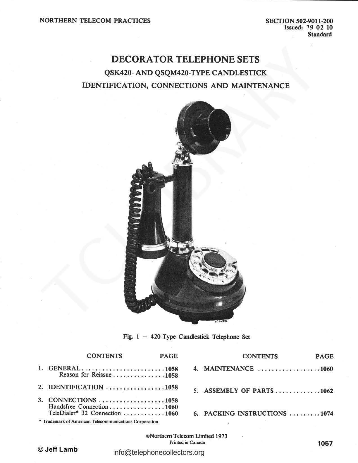
Fig. 1 - 420-Type Candlestick Telephone Set
CONTENTS PAGE CONTENTS PAGE
1.
GENERAL
.•..••••.••••••••••.•••.
1058
4.
MAINTENANCE
...•••.•..•••••.•.
1060
Reason for Reissue
....
. .
.....
.
...
1058
2.
IDENTIFICATION
.................
1058
5.
ASSEMBLY OF PARTS
..••••••••••.
1062
3.
CONNECTIONS
.•••.•.•
•
•••.••
•
••.
1058
Handsfree Connection . .
..
.
...
.
.......
1060
TeleDialer*
32
Connection
............
1060 6. PACKING INSTRUCTIONS .
••..•••
.1074
• Trademark
of
American Telecommunications Corporation
©Jeff Lamb
©Northern Telecom Limited 1973
Printed
in
Canada
1057

SECTION 502-9011-200
1. GENERAL
1.01
The Candlestick telephone set has a circular
base with the dial mounted in it. The
transmitter
is
situated approximately 8 inches
(203 mm) above the base. The receiver
han~s
on the
hook
at
the left side
of
the telephone set (Fig. I).
1.02 Reason for Reissue.
To
include new and
revised Figures, Charts and Tables. Because
of
the extent
of
the changes, margined arrows are not
used.
2.
IDENTIFICATION
2.01 Color codes for the
El
QSK420-and
QSQM420-
tyPC
telephone set are listed
in
Table.A.
TABLE A
QSK420-
AND
QSQM420-TYPE
TELEPHONE SETS
CODES
CODE
QSK420A
El
QSK421A
El
QSK422A
El
QSK423A
El
QSQM420A
QSQM421A
QSQM422A
QSQM423A
COLOR
Black
Red
White
Canadiana
Black
Red
White
Canadiana
2.02 The
El
QSK420-type telephone set is a single-
line, rotary dial set which is factory
wired
for
ring party service. The set is equipped with a
3-conductor, round, spade-tip-ended mounting cord.
The set can also be modified for use with NE-IAI
or
NE-IA2 Key Telephone Systems (KTS).
1058
info@telephonecollectors.org
,
2.03 The QSQM420-type telephone set
is
identical
in
appearance to the QSK420-type set,
however, it
is
factory wired for individual
or
bridged
party service and is equipped with a 4-conductor, flat,
plug-ended mounting cord.
2.04 The assoCiated apparatus for these telephone
sets (which must be ordered separately)
is
listed in Table
B.
TABLE B
ASSOCIATED APPARATUS
TELEPHONE SET
CODE
QSK420A
El
QSK421A
El
QSK422A
El
QSK423A
El
NE-lAl
OR
NE-1A2
KTS
NE
-D4BJ-03 Cord
NE
-D4BJ-53 Cord
NE-D4BJ-35 Cord
NE
-D4BJ-35 Cord
Not.e
: Associated apparatus must be ordered
separately.
El
Not
re
quired by
Bell
Canada
3. CONNECTIONS
3.01
Connections for all classes
of
sefvice are
shown in Table C. Wiring modifications for
use with
NE-IAI
or
NE-IA2
is
shown
in
Table E.
Not.e
: For QSQM420-type telephone sets, all
service modifications must
be
made
within
the
set.
©Jeff
Lamb

SECTION 502-9011-200
TABLE C
CONNECTIONS
FOR
QSK420-
AND
QSQM420-TYPE
TELEPHONE SETS
COLOR
INDIVIDUAL RING TIP
OR
BRIDGED PARTY PARTY
Mounting Cord RING R R R G
at Connecting
TIP
G G G R
Block (for
GRD
y G y y
QSK420-type AUX --- -
only)
RING
R L2 L2 L2 8
Mounting Cord TIP G
Lt
LI
LI
at Network
GRD
y G G G
AUX BK * * *
R A A A
Ringer (Note
1)
S-R * * *
s * · * *
BK
G(D
G G
s K K K
S-Y
L2 L2 L2
S-BR c c c
S-G
Ll
t
Ll
t
Lt
t
Line Switch S-W F F F
S-R
GN GN GN
S-BK R R R
0 • • •
BL * • •
* Indicates insulate and store
t Indicates a QCM15B connector
0 Indicates wiring differences for QSQM420-type telephone set.
TIP PARTY
2650 Q
IDENT
G
R
y
-
L2
8
Ll
G
*
A
B
*
G
K
L2
c
Ll
t
F
GN
R
*
•
Note:
To
permanently silence ringer, remove the (R) ringer lead from terminal A
of
the network.
G Not required by
Bell
Canada
©Jeff Lamb info@telephonecollectors.org
1059
SECTION 502-9011-200
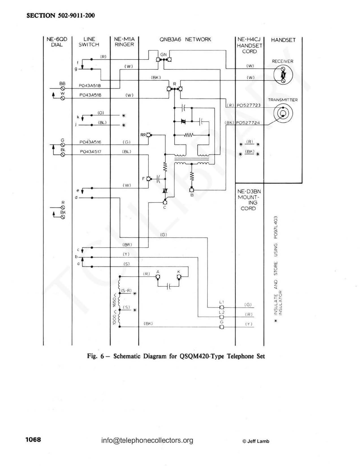
3.02 Schematic diagram for the
C!l
QSK420-type
telephone set
is
shown
in
Fig. 6. Schematic
diagram for the QSQM420-type set is shown in
Fig. 7.
3.03 The ringer volume control has a cutoff
position which
is
obstructed
by
a blocking
screw. To provide the ringer cutoff feature, remove
the ringer according to Chart 4, and remove the
blocking screw from the bottom
of
the ringer.
HANDSFREE CONNECTION
3.04 Connections
of
the
QUSlA
COMPANION•
Handsfree unit to the telephone set must
be
made within the set. A 2-conductor spade-tip-ended
mounting cord
is
required to make the connection.
Connections are to be made as follows (see Fig. 2):
• connect each lead, from one end
of
the
2-conductor mounting cord, to a
QCMl
2A
connector;
• connect the (BK) and (Y) leads
of
the
handsfree unit mounting cord to the same
QCM12A connectors;
• connect the (R) lead
of
the handsfree unit
mounting cord to terminal H
of
the network;
• connect the (G) lead
of
the handsfree unit
mounting cord
to
the QCM1
SB
connector
which
is
connected to terminal L1
of
the
network.
3.05
For
further information regarding handsfree
connection, refer to S12-6251-400.
TELEDIALER 32 CONNECTION
3.06 Connections
of
the QDM2AJ TeleDialer 32
to the telephone set
mu
st
be
made within the
set.
3.07
For
inpividual
or
bridged and ring party
service, proceed as follows (see Fig. 3[a]):
• disconnect the (R) telephone set mounting
cord lead from terminal L2
of
the network
and connect
to
the (R) TeleDialer lead using
a QCM12A connector;
• connect the (Y) TeleDialer lead to
terminal L2
of
the network;
•Trademark
of Northern Telecom Limited
1060
info@telephonecollectors.org
3.08
• connect the (G) TeleDialer lead
to
the
QCM15B connector which
is
connected
to
terminal L1
of
the network.
F?r
tip party service, proceed as follows (see
Fig. 3lb]):
• disconnect the (R) telephone set mounting
cord lead from terminal L1
of
the network
and connect
to
the (R) TeleDialer lead using
a QCM12A connector;
• connect the
(Y)
TeleDialer lead
to
terminal
LI
of
the network;
• connect the (G) TeleDialer lead
to
terminal H
of
the network.
3.09 For further information regarding TeleDialer
connection
s,
refer to 512-
1311
-200.
4. MAINTENANCE
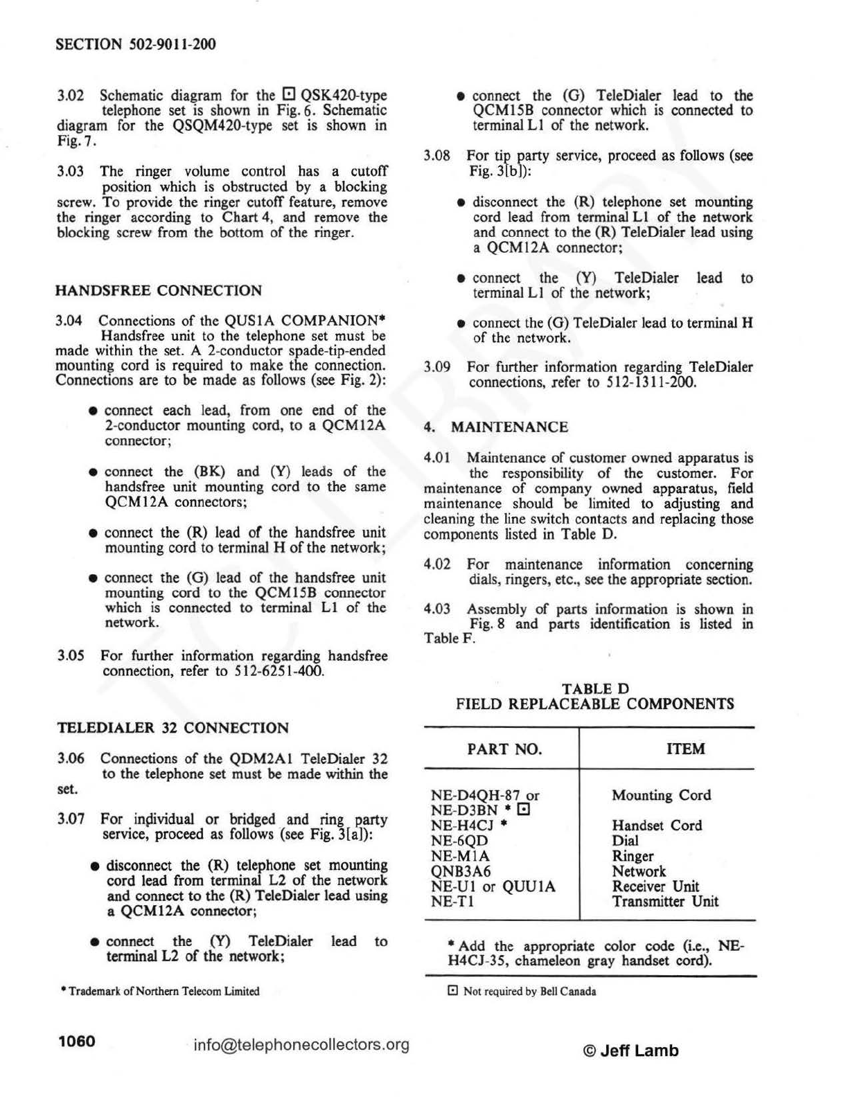
4.01 Maintenance
of
customer owned apparatus
is
the responsibility
of
the customer. For
maintenance
of
company owned apparatus,
field
maintenance should
be
limited
to
adjusting and
cleaning the line switch contacts and replacing those
components listed
in
Table D.
4.02 For maintenance information concerning
dials, ringers, etc., see the appropriate section.
4
.03
Assembly
of
parts information is shown in
Fig. 8 and parts identification is listed in
Table F.
TABLED
FIELD REPLACEABLE COMPONENTS
PART NO.
NE
-D4QH-87
or
NE
-D3BN •
C!l
NE
-H4CJ •
NE
-6QD
NE
-
MIA
QNB3A6
NE
-
Ul
or
QUUJA
NE
-
Tl
ITEM
Mounting Cord
Handset Cord
Dial
Ringer
Network
Receiver Unit
Transmitter Unit
• Add the appropriate color code (i.e.,
NE
-
H4CJ-35, chameleon gray handset cord).
El
Not required by
Bell
Canada
© Je
ff
Lamb

©Jeff
Lamb
SECTION S02-901
l-200
QUSIA
HANDS
-FREE
UNIT
QCMl5B
CONNECTOR
QDM2AI
TELEDIALER
(BK)
QCMl2A
CONNECTOR
NE-20128 TRANSFORMER
OR
EQUIVALENT
Fig. 2 - Handsfree Connections
CMl2A
CONNECTOR
1--~~~<R~)~~~-+-.__.~+-~~-+---'(~R~)~•
t--~~~(Y~)~~~-+----+~
G
Fig. 3(a) -TeleDialer Connections for Individual
or
Bridged
and
Ring Party Service
QCMl2A
CONNECTOR
\
L~
(R)
(R)
-,
QDM2AI (Y)
,~
TELEDIALER
(G)
:rli-<
TELEPHONE SET
Fig. 3(b) -TeleDialer Connections for Tip Party Service
info@telephonecollectors.org
1061

SECTION 502-9011-200
TABLE E
NE
-
lAl
OR
NE
-1A2 KTS CONVERSION
COLOR REMOVE FROM
CONNECT
TO
NETWORK TERMINAL NETWORK TERMINAL
G -t
Mounting Cord R -L2
y -G
BK -
LI
Ringer BK G t
S-G
u(f)
H
S-
BR
c G
Line Switch S-W F c
s K •
S-Y L2
LI
QCMI5B Connector
Ll
F
NE
-
MI
W Cord
or
Equivalent Strap K to L2
t Indicates a QCMI5B connector
0 Indicates wiring differences for QSQM420-type telephone set.
S.
ASSEMBLY
OF
PARTS
5.
01
The procedures for substituting the
field
replaceable components (see TableD)
in
the
QSK420- and QSQM420-type telephone sets are
contained
in
the following charts:
Chart 1 Removing the Base Assembly
Chart 2 Replacing the Dial
Chart 3 Replacing the Line Switch
10
62 info@telephonecollectors.o
rg
Chart 4 Replacing the Ringer
Chart 5 Replacing the Network
Chart 6 Replacing the Mounting Cord
Chart 7 Replacing the Handset Cord
Chart 8 Replacing the Spider and Lead
Assembly,
or
Bracket and Lead
Assembly.
© Je
ff
La
mb

SECTION 502-9011-200
CHART 1
REMOVING AND REPLACING
THE
BASE ASSEMBLY
STEP PROCEDURE
REMOVAL
1 Remove the receiver from the hook.
2 Remove the four screws (Fig. 8, Item 62) which secure the base assembly to the housing
assembly.
3 Lift the housing from the base assembly. Take care not to break the two transmitter leads.
REPLACEMENT
4 Place the housing over the dial, avoiding undue force. The fmgerwheel stop and dial adapter ring
-notch must
be
aligned.
5 Using asmall screwdriver, pry the lower left adapter tab away from the dial (Fig. 4[a]). Press
down on the housing until it drops (about 1/8 inch
or
3.2 mm) into place.
6 Check thatthe other two tabs have cleared the dial.
If
not, push the tabs back with a screwdriver
(Fig. 4[b]).
STEP PROCEDURE
CHART
2
REPLACING
OF
THE
DIAL
1 Remove the base assembly according to Chart
1.
2 Remove the screw (Fig. 8, Item 65) from the platform on which the dial and line switch are
mounted. Lift the platform from the base.
3 Disconnect the leads from the dial.
4 Remove the three mounting screws which fasten the dial to the platform.
5 Replace the dial. See Schematic Diagram, Fig. 6
or
7 , for connections.
©
Jeff
Lamb info@telephonecollectors.org
1063

SECTION 502-9011-200
1064
SCREWDRIVER
DIAL FINGERWHEEL
\ TELEPHONE
SET
HOUSING
DIAL
Fig. 4(a) -Installing Housing Assembly, Chart I, Step S
DI
AL
FINGERWHEEL
SCREWDRIVER
DIAL
TELEPHONE
SET
HOUSING
Fig. 4(b) -Installing Housing Assembly, Chart
1,
Step 6
info@telephonecollectors.org ©
Jeff
Lamb
SECTION 502-9011-200
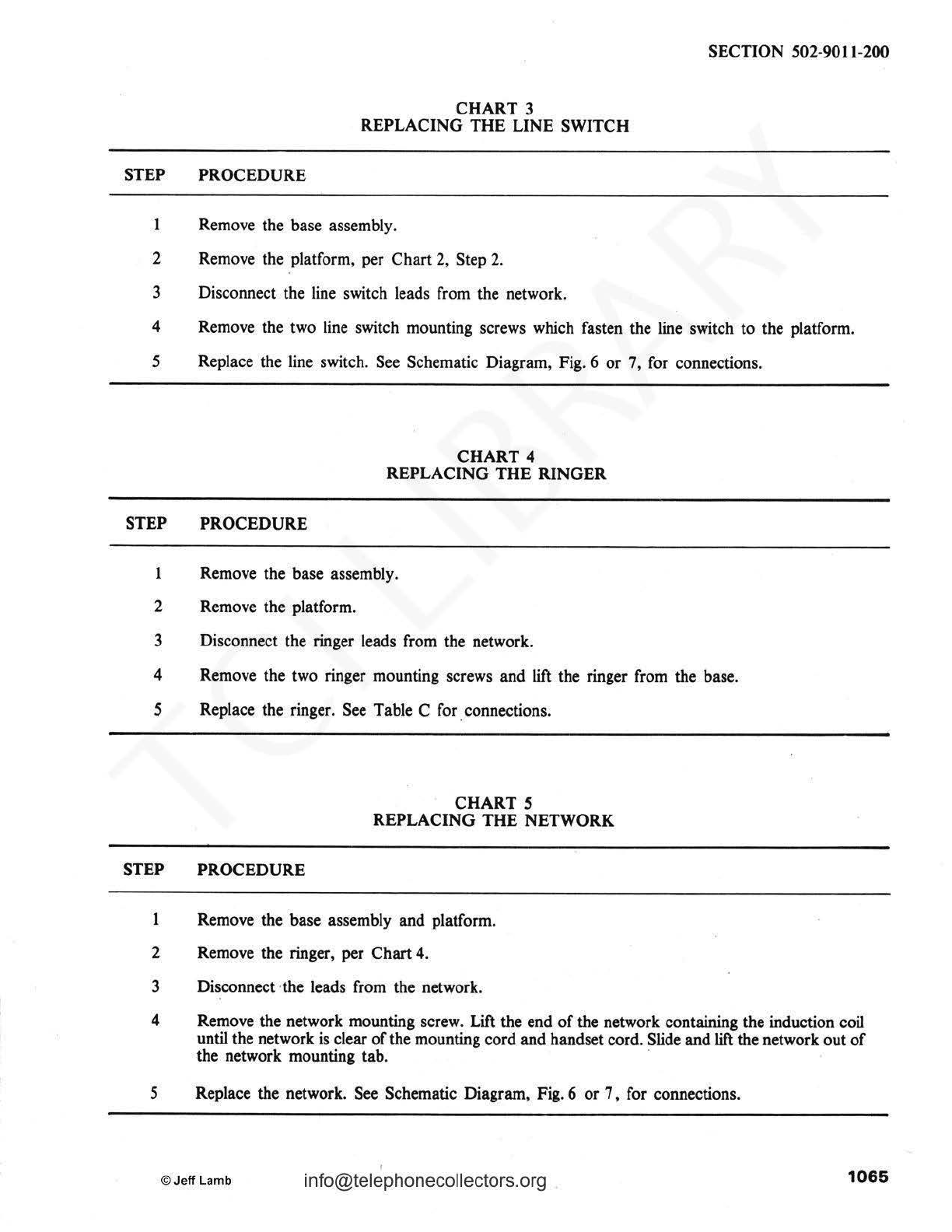
STEP PROCEDURE
CHART
3
REPLACING
THE
LINE SWITCH
1 Remove the base assembly.
2 Remove the platform, per Chart 2, Step
2.
3 Disconnect the line switch leads from the network.
4 Remove the two line switch mounting screws which fasten the line switch to the platform.
5 Replace the line switch. See Schematic Diagram, Fig. 6
or
7, for connections.
STEP PROCEDURE
CHART 4
REPLACING
THE
RINGER
1 Remove the base assembly.
2 Remove the platform.
3 Disconnect the ringer leads from the network.
4 Remove the two ringer mounting screws and lift the ringer from the base.
5 Replace the ringer. See Table C for .connections.
STEP PROCEDURE
CHART
5
REPLACING
THE
NETWORK
Remove the base assembly and platform.
2 Remove the ringer, per Chart
4.
3 Disconnect·the leads from the network.
4 Remove the network mounting screw. Lift the end
of
the network containing the induction coil
until the network
is
clear
of
the mounting cord and handset cord. Slide and
lift
the network out
of
the network mounting tab. ·
5 Replace the network. See Schematic Diagram, Fig.6
or
7, for connections.
I
©
Jeff
Lamb
info@telephonecollectors.org
1065

SECTION 502-9011-200
CHART 6
REPLACING
THE
MOUNTING
CORD
STEP PROCEDURE
1 Remove the base assembly and platform.
2 Disconnect the mounting cord leads from the network.
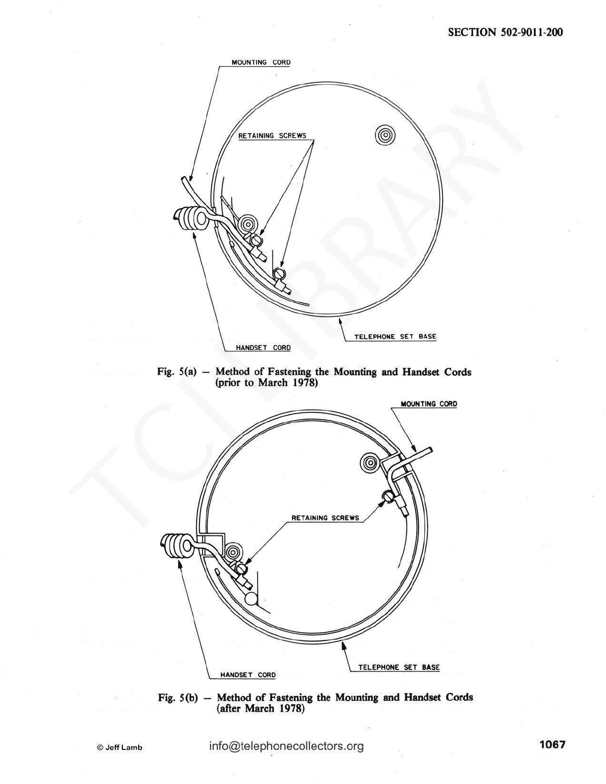
3 Loosen the screw to free the staycord hook, and remove the mounting cord.
(See
Fig. 5[a] or
5[b]~
.
4 Replace the mounting cord.
See
Table C for connections.
CHART 7
REPLACING THE HANDSET CORD
STEP PROCEDURE
1 Remove the earpiece cap from the earpiece housing, and discoanect the handset cord leads from
the receiver unit.
2 Unscrew the hook fitting (Fig. 8, Item 116) and
pull
the handset cord from the earpiece housing.
3 Remove the cord restraint and
pull
the cord from the hook fitting.
4 Remove the handset cord from the telephone set base
in
a similar manner
to
the mounting cord.
(See
Chart6,
Fig.5[a) or S[b]).
5 Replace the handset cord. See Schematic Diagram, Fig. 6 or 7, for connections.
CHART 8
REPLACING THE SPIDER AND LEAD ASSEMBLY
OR
BRACKET AND LEAD ASSEMBLY
STEP PROCEDURE
1066
Unscrew the transmitter cap and remove the spider and bracket from the transmitter unit.
2 Remove the base assembly and platform.
3 Disconnect the leads from the network.
4 Release the leads from the screws and washers which clamp the leads to the inside
of
the
telephone set housing.
5
Pull
the leads out through the transmitter housing assembly.
6 Replace the spider and bracket.
See
Schematic Diagram, Fig. 6
or
7,
for connections.
info@telephonecollectors.org ©
Jeff
Lamb
©
Jeff
Lamb
SECTION 502-9011-200
MOUNTING
CORD
TELEPHONE SET BASE
HANDSET
CORD
Fig. S(a) -Method
of
Fastening the Mounting and Handset Cords
(prior to March 1978)
RETAINING
SCREWS
TELEPHONE SET BASE
HANOSET
CORO
Fig. S(b) -Method
of
Fastening the Mounting and Handset Cords
(after March 1978)
1067
SECTION
502-
9011
-200
NE-
60D
LINE
NE-MlA
0NB3A6
NETWORK NE-H4CJ HANDSET
DIAL
SW
I
TCH
RI
NGER
HANDSET
CORD
(R)
I
RECE
IVER
(W)
(W)
g
(BK)
(W)
BB
P043A518
w
P043A518
(W)
TRANSMITTER
R
?052772
3
(0)
*
k
(BL)
*
(8K)
P0527724
G P043A516
<GJ
*JB.l..*
BL
P043A5
17
(BU
*
(BK)*
F
(W)
e NE-D3BN
d B MOUNT-
R ING
--{9
c CORD
~
<')
0
<1
J
....
(G)
Ol
0
a.
(
BR
)
<.!)
c z
Vi
tl
(
Y)
::>
0
(S)
w
0:
0
,_
<ll
0
z
<l'.
er
< wo
~
,_
,_
L1
<l'.
<l'.
~
<
GJ
_J _J
::> ::>
<
<llt/l
L2
IR)
~~
0
0 G *
Q
(BK
)
(Y)
Fig.
6 -
Schematic
Diagram
for
QSQM420-Type
Telephone
Set
1068
info@telephonecollectors.org ©
Jeff
Lamb

SECTION
502-9011-200
TING
MOl..N
co
AU)(
RINGER
LINE
SWITCH DIAL NETWORK HANDSET HANDSET
RD
<
BK
I CORD
* -
ORD
(Y)
(WI
r
;!J
~
IWl
$ 1
(R)
L.
--
>-<
~
lYI
_
LZ
(RI
GN
llCYR
~
RINll
-
fl
1111
I!.I (WI .
• -(
Il
l)
-
II
0 ! (WI l
-
-(W) R -..
,I---
• 10) k
,_
•
Ill)
+I llU -- \
..
.
.~
.
e
~
-
>;
I I
..
~.
.i
(0)
d t -
~L
(BL)
.>
""""'""'
-A:.>
-
lW)
-, >
~
.>
llK)
,.._
:::
I
(BIO
c le _
_ib
-~
-(Ill)
0 I
TllllTR
R
---0
UJ
NOTES
f.
IGl
L llflNS
IA.AT
ED
ANO
STORED
I (BK)
-~
2-
ltQC
M
l
~B
CO
NNE
CTOR
ISi
-~
INOT
E2
)
.s.
• ISi
~
~
.
~
IRI
.,,
-~
J?
- -
IGI
N ;,;
Tl '
Fig.
7-
Schematic Diagram for QSK420-Type Telephone Set
CHART
9
ADJUSTING
TRANSMITTER
HEAD
POSITION
STEP
PROCEDURE
Caution:
The
movement
of
I.he
transmitter
head
cannot
be
restricted
by
over-tighlenlng
I.he
moundng
screw.
Remove the mounting screw, spring and hinge pin assembly (Fig. 8, Items 63, 88 and 12S).
2 Stretch the spring to increase its length.
3 Replace the spring, hinge pin and screw through the upper column and transmitter housing
assembly.
4 Tighten the mounting screw:
Note:
The key
in
the hinge pin must
fit
into the corresponding upper column key slot.
©JeffLamb info@telephonecollectors.org
1089

SECTION 502-
9011
-200
Fig. 8 - QSK420-and QSQM420-Type Telephone
S~
Assembly
of
Parts (Table F)
1070
info@telephonecollectors.org ©JeffLamb

IDENTIFICATION
NT
PART
ITEM NO.
NUMBER
1 -
2 -
3 -
ISB P043AS16
168
P043AS17
178 P043AS18
228 POS27723
248
POS27724
30 QNB3A6
NE
-
MIA
32
NE
-
6QD
34
NE-Ul
or
36
QUUIA
NE
-
Tl
40
NE-H4CJ-3
NE
-H4CJ-
S3
NE-H4CJ-3S
47
NE-D3BN-3
NB-D3BN-53
NE-D
3BN
-35
NE-D4QH
-87
61 C0039111
62
C0039008
63 C0039013
64
C0038009
65
C0039001
70 C0039112
72 C0039009
74 C0039002
76 C0039036
80
C0039010
82 C0038078
84 C00390S3
86 C00390S4
8 Not required by Be
ll
Canada
TABLE F
IDENTIFICATION OF PARTS
ATC
DESCRIPTION
PART
NO.
-Screw, PHMS, 0.112-36
(4
-
36)x3/16
inch long
-Screw, PHMS, 0.112-36
(4-36)xS/
16 inch
lo
ng
-Screw,
PHMS,
0.112-40
(4-40)x1/2 inch long
-Lead Assembly
Note
1
-
Lead
Assembly Note 1
-Lead Assembly Note 1
-Bracket
and
Lead
Assy
-Spider and Lead Assy
-Network
Ringer
-Dial
-Receiver Unit
-Transmitter Unit
-
-Cord, Handset
-
-
-Cord, Mounting
-
-
7198 Screw
4189 Screw
7139 Screw .
7109 Screw
7149 Screw
7144
Wuher
7145 Lock Washer
7151 Stat Washer
4122 Housing Washer
7143 Pal
Nut
2212
Foot
4212 Network Mounting
Tab
4213 Ringer Mounting Kit
T l
ab
e Continu
ed
©
Jeff
Lamb infor@telephonecollectors.org
Q
s
K
4
2
0
A
1
3
2
1
1
2
1
1
1
1
1
1
1
I
1
2
4
1
2
1
2
1
2
I
2
4
1
1
SECTION
502
-
9011
-
200
[!]
Q Q Q Q
Q Q Q s s s s
s s s Q Q Q Q
K K K M M M M
4 4 4 4 4 4 4
2 2 2 2 2 2 2
I 2 3 0 I 2 3
A A A A A A A
1 I I I I 1 1
3 3 3 3 3 3 3
2 2 2 2 2 2 2
1 I 1 1 1 1 1
1 1 1 1 1 1 1
2 2 2 2 2 2 2
1 1 1 1 1 1 1
1 1 1 1 1 1 1
1 1 1 1 1 1 1
1 1 1 1 1 1 1
1 1 1 1 1 1 1
1 1 1 1 1 I I
1 1 1 1 1 1 I
1
I 1
1 1 1 1
1
1 1 1 1 1 1
2 2 2 2 2 2 2
4 4 4 4 4 4 4
I I I I 1 1 1
2 2 2 2 2 2 2
1 1 1 1 1 1 1
2 2 2 2 2 2 2
1 l 1 1 1 1 1
2 2 2 2 2 2 2
I 1 I 1 I I 1
2 2 2 2 2 2 2
4 4 4 4 4 4 4
1 1 1 1 1 1 1
1 1 1 1 1 1 1
107
1

SECTION 502-9011-200
IDENTIFICATION
NT
PART
ITEM NO. NUMBER
88 C0039012
90 C0039011
92 C0045638
94 C0039015
96 C0039016
98 C0039020
100 C0039027
102 C0039028
104 C0039035
106 C0039055
108 C0039117
112 C0039017
C0039018
C0039019
113 C0039021
C0039022
C0039023
114 C0039024
C0039025
C0039026
C0038118
C0046884
116 C0039032
C0039033
C0039034
115
C0039029
C0039030
C0039031
117 C0039050
C0039051
C0039052
119 C0039040
C0039041
C0039042
C!l
Not
required
by
Bell
Canada
TABLE F Continued
IDENTIFICATION
OF
PARTS
ATC
DESCRIPTION
PART
NO.
4162 Spring
4119 Acutator Spring
4139 Transmitter Gasket
4120 Acutator Guide Tube
4106 Upper Fitting Column
4155 Hook Support
4107 Lower Fitting Column
4117 Actuator Sleeve
4144 Lower Ferrule
4211 Platform
4704 Actutator Button
4109-B (Black)
4109-R Transmitter (Red)
4109-W Housing {White)
4116-B
4116-R Hook
4116-W
4105-B
4105-R
4105-W Column
4105-M
4166
4114-B Hook Fitting
4114-R
4114-W
4167-B
4167-R Cord Restraint
4167-W
4206-B
4206-R Dial Adaptor Ring
4206-W
4113-B
4113-R Earpiece
Cap
4113-W
Table Continued
1072
El
Q Q Q Q
Q Q Q Q s s s s
s s s s Q Q Q Q
K K K K M M M M
4 4 4 4 4 4 4 4
2 2 2 2 2 2 2 2
0 I 2 3 0 I 2 3
A A A A A A A A
I 1 I 1 1 1 1 1
1 1 1 1 1 1 1 1
1 1 1 1 1 1 1 1
1 1 1 1 1 1 1 1
1 1 1 1 1 1 1 1
1 1 1 1 1 1 1 1
1 1 1 1 1 1 1 1
1 1 1 1 1 1 1 1
1 1 1 1 1 1 1 1
1 1 1 1 1 1 1 1
1 1 1 1 1 1 1 l
1 1
1 1 1 l
1 1
1 1
l 1
1 1 1 1
1 1
1 1
1 1
l 1
I I
1 1
1 1 I 1
l 1
1 1 1 1
1 1
1 1
1 1 l l
l l
1 1
1 1 1 1
1 1
©
Jeff
Lamb

IDENTIFICATION
NT
PART
ITEM NO. NUMBER
120 C0039037
C0039038
C0039039
C0039119
125 C0039049
128 C0039056
131
C0039057
136 C0039046
C0039047
C0039048
C0039121
137
C0039043
C0039044
C0039045
C0039120
1380
·C0039131
C0039127
C0039130
1390
P0
896341
Notes:
TABLE F Continued
IDENTIFICATION
O~
PARTS
ATC DESCRIPTION
PART
NO.
4112-B
4112-R
4112-W Earpiece Housing
4112-M
4168 Hinge Pin Assembly
4210-lB Base Assembly
4214 Line switch and bracket
assembly
4193-B
4193-R Transmitter
Cap
4193-W Assembly
4123-M
4123-B
4123-R
4123-W Housing Assembly
4123-M
4215-B
4215-R Dial Insert
4215-W
Ca
rd
Holder Parts Group
(Note 2)
1.
Items
15B
,
16B
and l
7B
are shown on Fig. 2 and Fig.
3.
Q
s
K
4
2
0
A
l
1
1
1
1
1
1
l
SECTION 502-
9011
-200
El
Q Q Q Q
Q Q Q s s s s
s s s Q Q Q Q
K K K M M M M
4 4 4 4 4 4 4
2 2 2 2 2 2 2
l 2 3 0 l 2 3
A A A A A A A
l
l 1
1 1
1 1
1 1 l 1 1 l 1
1 1 1 1 1 1 1
1 1 1 1 1 1 1
1
1 1
1 1
1 l
1
1 1
1 1
1 1
1
1 1 1 l
1 1
1 1 1 1 1 1 1
2.
Item 1
390
is shipped with each dial'(Item 32) when ordered for replacement purposes.
El
Not required by
Bell
Canada
©
Jeff
Lamb info@telephonecollectors.org
1073

SECTION 502-9011-200
6. PACKING INSTRUCTIONS
6.01 Candlestick telephone sets can
be
easily
damaged in transmit
if
they are not properly
packaged. Before returning a disconnected set,
carefully pack it in accordance with the following
instructions.
• Obtain the original packing material.
• Gather the mounting cord as shown
in
Fig. 9,
place the cord in a plastic bag, and secure
with an elastic band.
• Take the receiver off-hook, and place a large
plastic bag completely over the telephone set
with the bag opening
at
the base.
• Position the set
in
the one
of
the foam inserts
as shown. Place the mounting cord
in
the
large rectangular recess at the bottom
of
the
insert.
• Place a plastic bag completely over the
receiver.
• Position the receiver in the insert as shown
in
Fig.
9.
Arrange the cord so that it rests
between the receiver and the telephone set.
• Place the two inserts together and put the
complete assembly into the carton.
Fig. 9 - Candlestick Telephone Set Packing Instructions
1074
info@TelephoneCollectors.org ©Jeff
lamb
This manual suits for next models
10
Other Northern Telecom Telephone manuals

Northern Telecom
Northern Telecom DisplayPhone User manual

Northern Telecom
Northern Telecom DMS-100 Series Operating manual

Northern Telecom
Northern Telecom Meridian M3000 User manual

Northern Telecom
Northern Telecom M5212 ACD Operating and installation instructions

Northern Telecom
Northern Telecom Logic 10 User manual

Northern Telecom
Northern Telecom IMAGINATION QSK450 Operating and installation instructions

Northern Telecom
Northern Telecom QSK 100 Instruction Manual

Northern Telecom
Northern Telecom M5317TX User manual

Northern Telecom
Northern Telecom Unity Two-Line User manual

Northern Telecom
Northern Telecom Compact ICS 4.0 User manual


