MANUFACTURED BY
©MMXNORWECO,INC.NORWALK,OHIOU.S.A.
NORWECO, INC.
NORWALK, OHIO
U.S.A. 44857
www.norweco.com
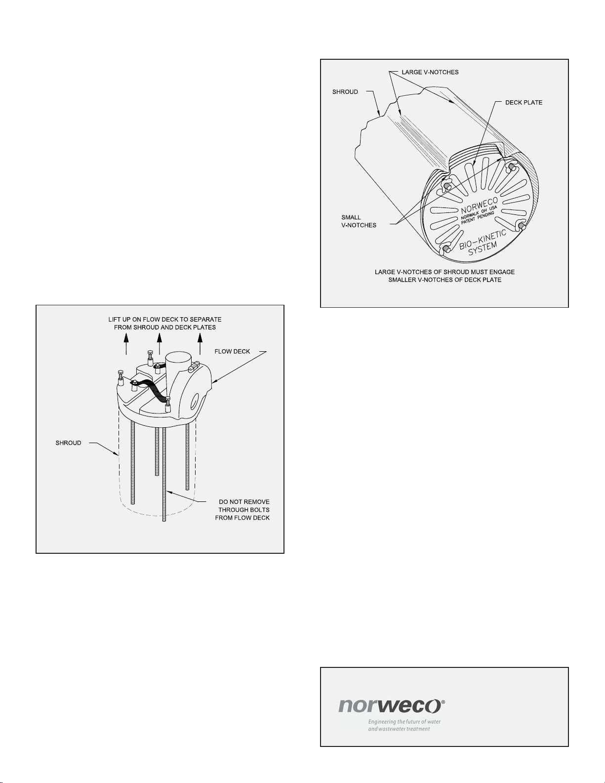
wallshroud. Do notremove thethrough boltsfrom the
flow distribution deck. Rinse the flow distribution deck
thoroughly inside and out. Inspect the weir and final
discharge zone to be sure they are completely clean.
5. Liftupthe bafflewall shroudto remove itfrom thedeck
plates. Rinsethe insideand outside ofthe shroudand
setit aside. Takethe cleaned,roundbottom deckplate
and set it on the floor with the engraved name facing
down.
6. Remove the top deck plate from the remaining stack
and wash off both sides. When cleaned, set it on top
of the cleaned, round bottom deck plate. Repeat this
procedure with each deck plate until all plates are
cleaned and reassembled into a single stack. Each
deck plate is molded with four circular depressions in
the bottom side of the plate and four round stand-off
posts in the top side of the plate. When restacking the
clean deck plates, make sure the four depressions on
the bottom engage the top of the four posts below. All
deck plates must be placed onto the stack baffle side
up (engraving down). When properly assembled, all
edgesof eachplate shouldbevertically aligned.
7. Lowerthebaffle wallshroud overthe assembled stack
of deck plates. The two large V-notches in the shroud
should engage the smaller notches on the edge of the
deck plates. Check the four leveling lugs on the flow
deck. They must be unscrewed until they are flush
withthe bottomof theflowdeck. Now positionthe flow
distribution deck above the baffle wall shroud so that
the outlet of the flow distribution deck is directly
opposite the two large V-notches in the shroud. Insert
each of the four through bolts through the holes in the
topofthebaffleshroudand intothestack ofdeckplates.
Lower the flow distribution deck until it fully engages
BIO-KINETIC®SYSTEM CLEANING AND DISASSEMBLY INSTRUCTIONS (Cont.)
the top of the baffle shroud. Push each through bolt
down into the assembly as far as it will go.
8. Laytheassemblyon its sideandpushthe throughbolts
through the bottom deck plate. Fasten a wing nut to
each of the four through bolts where they project
through the bottom deck plate. While tightening each
wing nut, make sure the molded plastic tabs on the
bottom deck plate engage the slots on the edge of the
shroud. Tighten enough to insure all three tabs are
fully engaged into the three slots in the shroud.
9. Lubricate the grommet in the outlet opening of the
contact chamber. Grasp the strap handles and lower
theflowdeck andinternalcomponents intothe cleaned
contact chamber making sure to align the flow deck
outlet with the outlet of the contact chamber. Apply a
moderate amount of downward force until the outlet of
the flow distribution deck aligns with the outlet of the
contact chamber.
10. Place the assembled Bio-Kinetic system back into the
cleanedservice container. Placethe dischargeflange
assembly onto the flow distribution deck. Now place
theservice containercoverinto positionbyaligning the
fourholes inthe coverwith thelocking lug bolts. Adda
wing nut to each of the lug bolts to hold the cover in
place. Return the container to your service stock.
DECK PLATE AND SHROUD ASSEMBLY
REMOVE FLOW DECK FROM SHROUD


