Shannon HRP/D User manual
User’s Guide
English
Plastic bending machine
HRP/D

User’s guide
HRP/D
-1-
HS
User’s Guide
Plastic bending
machine
HRP/D
2002 SHANNON BV. All rights reserved.
No part of this User's Guide may be photocopied, altered
or translated without prior written consent.
Information contained in this User's Guide is subject
to change without notice.

User’s guide
HRP/D
-2-
HS
Contents
Contents 2
Introduction 4
1 Description of the machine 5
2 Technical data 6
3 Safety instructions 7
4 Safety devices 9
4.1 Emergency top switch 9
4.2 Emergency stop 9
4.3 Air pressure monitoring 9
5 Legend 10
5.1 Overview 10
5.2 Switch unit 11
5.3 Timer unit 11
5.4 Air unit 11
5.5 Control unit 12
6 Installation 13
6.1 Assembly 13
6.2 Connecting compressed air 13
6.3 Connecting power cable 13
6.4 Connecting foot switch 13
7 Operation 14
7.1 Preparation 14
7.2 Switching on control units 14
7.3 Switching on top frame 14
7.4 Switching on heating elements 15
7.5 Setting temperature 15
7.6 Setting cycle time 15
7.7 Hand or foot operation 16
7.8 Setting air pressure 16
7.9 Resetting top emergency switch 16
7.10 Switching on transportsystem 17
8 Adjustment 19
8.1 Safety measures 19
8.2 Lower heating element 19
8.3 Upper heating element and pressure bar 21
8.4 Lower filament height 21
8.5 Upper filament height 22
8.6 Stop 23

User’s guide
HRP/D
-3-
HS
Contents
9 Alterations 24
9.1 Safety measures 24
9.2 Lower heating element 24
9.2.1 Removal 24
9.2.2 Installation/replacement 25
9.3 Upper heating element and pressure bar 27
9.3.1 Removal 27
9.3.2 Installation 28
10 Maintenance 30
10.1 Safety measures 30
10.2 Lubrication points 30
10.2.1 Cylinder bearing: bottom 30
10.2.2 Cylinder bearing: top 30
10.2.3 Bearing blocks 31
10.3 Profiles 31
10.4 Water separator 31
10.4.1 Checking 31
10.4.2 Emptying 32
11 Trouble shooting 33
12 Installation and removal of units 34
12.1Safety measures 34
12.2 Control unit 34
12.2.1 Removal 34
12.2.2 Installation 35
12.3 Timer/switch unit 36
12.4 Main switch box 36
12.4.1 Removal 36
12.4.2 Installation 37
13 Tensioning and changing filament 38
13.1Safety measures 38
13.2 Tensioning 38
13.3 Changing 39
14 Fuse 41
14.1 Safety measures 41
14.2 Control unit fuse 41
14.3 Restoring circuit breaker 42
14.4 Main switch box fuse 42
Annexes 44
A Machine summary 44
B Diagram control unit 45
C Diagram timer unit 46
D Diagram switch unit 47
E Diagram pneumatic system 48
F Dimensions 49
G Options 50
Accessories
51

User’s guide
HRP/D
-4-
HS
Equipment
51
H Service and warranty 53

User’s guide
HRP/D
-5-
HS
Introduction
Congratulations on purchasing the Shannon HRP/D plastic
bending-machine.
Read this Guide completely before installing and using the
machine.
We want to keep in contact and to know how you find the
HRP/D. We are always willing to advise on the use of the
machine and its accessories.
SHANNON BV
Turfschipper 11 - 13
2292 JC WATERINGEN
P.O. box 84
2290 AB WATERINGEN
The Netherlands (EC)
Tel: +31 (0)174-225 240
Fax: +31 (0)174-225 249
E-mail: [email protected]
Website: www.shannon.nl

User’s guide
HRP/D
-6-
HS
Description of the machine
The Shannon HRP/D plastic bending-machine is a rapidly
convertible semi-automatic bending machine for the
production of large series of items with multiple bends for the
plastic sheet processing industry.
The machine has four adjustable heating elements as
standard, the temperature of which can be adjusted by
electronic controls.
The filaments of the heating elements on the working
surface are adjustable in height. The other elements, which
are mounted in the pneumatically operated top frame which
clamps the workpiece in place, are adjustable in height as a
single unit in respect of the working surface.
The workpiece can be heated from two sides, considerably
reducing the production cycle time and making it possible
with multiple-wire reflectors to bend sheet up to 20 mm
thickness.
The top frame is switched on independently of the control
units and is controlled by an adjustable timer.
The working surface is made of scratch-resistant solid core
material with which the space between the zones to be
heated can be filled to support the plastic sheet.
The machine has facilities for the mounting of additional
heating elements at both top and bottom. The elements can
be mounted by the user.
The machine is also equipped with an automatic transport-
system exsisting of feedbelts and a speedcontroller.
When heated, thermoplastics become so flexible that they can
be shaped. When a plastic sheet is heated to its softening point
in a narrow zone, if can be bent to any angle desired.
The bending radius is determined by the width of the heated
zone. The zone is determined by the thickness of the material,
the type of heating element and the distance between the
plastic and the filament.
Every plastic has its specific softening point. By co-ordinating
the temperature, heated zone and heating time all kinds of
thermoplastic can be processed.
1

User’s guide
HRP/D
-7-
HS
Technical Data
model
HRP/D
Assembly
control
4 (max. 8)
lower heating element
2 (max. 4), fitted with single filament
upper heating element
2 (max. 4), fitted with single filament
pressure bar
2 (max. 4)
Feed belts
3 (max. 6)
Speed controller
1
options
see Annex G
Electrical
voltage
power
fuse
timer unit
24 V=
15 VA
100mAT
switch unit
380/220 V~
20 VA
250 mAT
control unit
220/240 V~
1000 VA
5 AT
Driving motor
24 V
45 VA
Speed-controller
220/240 V
144 VA
max. power requirement
8.000 VA
circuit breaker
3x16 A
connection
CEE 4 32A 3P+0+A
network connection
CEE 4 32A 3P+0+A
Network ciruitbreaker
Min 3x16 A
filament
0-30 V, 0-19 A ~
diagram
see Annex B, C and D
Pneumatic
air
Unlubricated clean dry air
maximum
8 bar
minimum
3.5 bar
working pressure
6 bar
coupling
Festo quick action coupling
air consumption
21.6 Nl per cycle at 6 Bar
diagram
see Annex E
Mechanical
speed of top frame
rad/s (20cm/s at front)
force on plastic
approx. 3.5 kg/cm²
gradation of stop
0-1000 mm
dimensions
3390x1300x1092 mm (lxwxh) see Annex F
weight
750 Kg
life of filament
Approx. 600 hours
Functional
bending width
3000 mm
mutually extendible
1000 mm (max.)
sheet thickness
1 - 20 mm (depending on heating element)
setting range timer
0-9999 sec
temperature range filament
20-600 C
filament height adjustment
bottom
1 - 17.5 mm
top
7 - 26 mm
Ambient
temperature
18-30 C
humidity of the air
50-80 % (no condensed)
Miscellaneous
set of socket screw keys
2, 3, 5, 6mm 1 x
spare fuse
5x20mm 250 mAT 1 x
spare fuse
6.3x32 5 AT 4 x
spare filament
1.6 x 3150 / 2150mm 2 x / 2x
2

User’s guide
HRP/D
-8-
HS
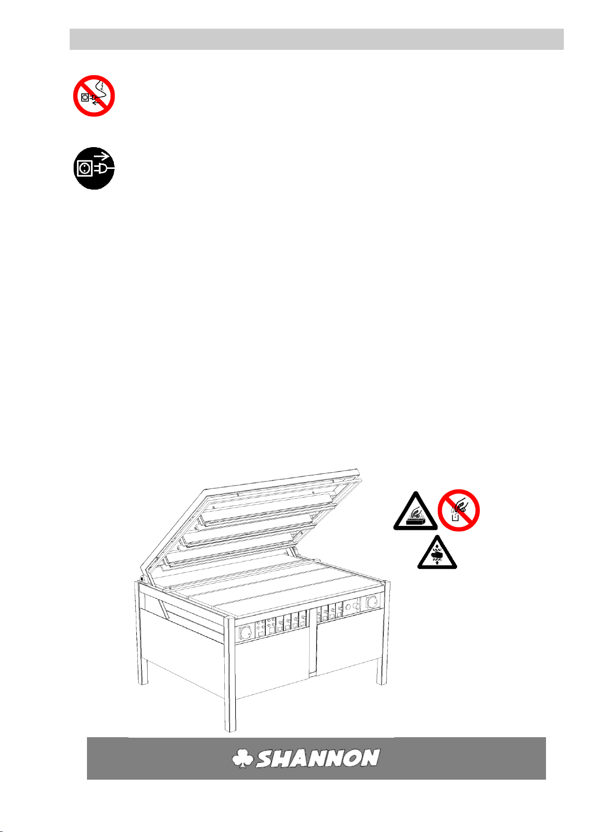
Safety instructions
SAFETY INSTRUCTIONS:
To ensure safety when using the machine you should read this
User's Guide carefully and follow the safety instructions closely.
Attention!
The machine contains a section where there is a risk of
trapping.
Attention!
The machine contains parts which are hot. Touching them will
cause burns.
Allow hot parts to cool sufficiently (at least 10 minutes) before
touching them.
Never touch the filaments or the reflectors when the machine
is in operation.
Always wear close-fitting clothing.
Be particularly careful of sleeves and always tie back long hair.
Never leave objects on the working surface.
The machine may only be used for heating narrow zones in flat
plastic sheet.
Any other use could lead to very hazardous situations or cause
damage to the machine!
The plastic sheet to be bent should never be more than 20 mm
thick.
3
User’s guide
HRP/D
-9-
HS
Safety instructions 3
Before commissioning and servicing always check the
connection cable and plug for defects.
When servicing switch off the machine and remove the plug
from the socket.
When the machine is temporarily out of use always remove
the foot switch and keep it in a safe place.
Before use always check that all the pressure bars and heating
elements in the top frame are firmly attached.
Only switch on those heating elements which are needed.
Never operate the machine if anyone is standing close behind
or beside it.
Never introduce objects or material into the machine from the
rear.
Never leave the machine unattended without switching it off.
User’s guide
HRP/D
-10-
HS
Safety devices
The machine is equipped with the following safety devices:
4.1 EMERGENCY TOP SWITCH
When the emergency top switch is touched the power on the
top frame is interrupted and the machine opens. This avoids
limbs becoming trapped. The red lamp (J) on the timer unit
lights and the timer (K) is returned to zero (see also § 5.3.) The
timer unit must be reset after a stop.
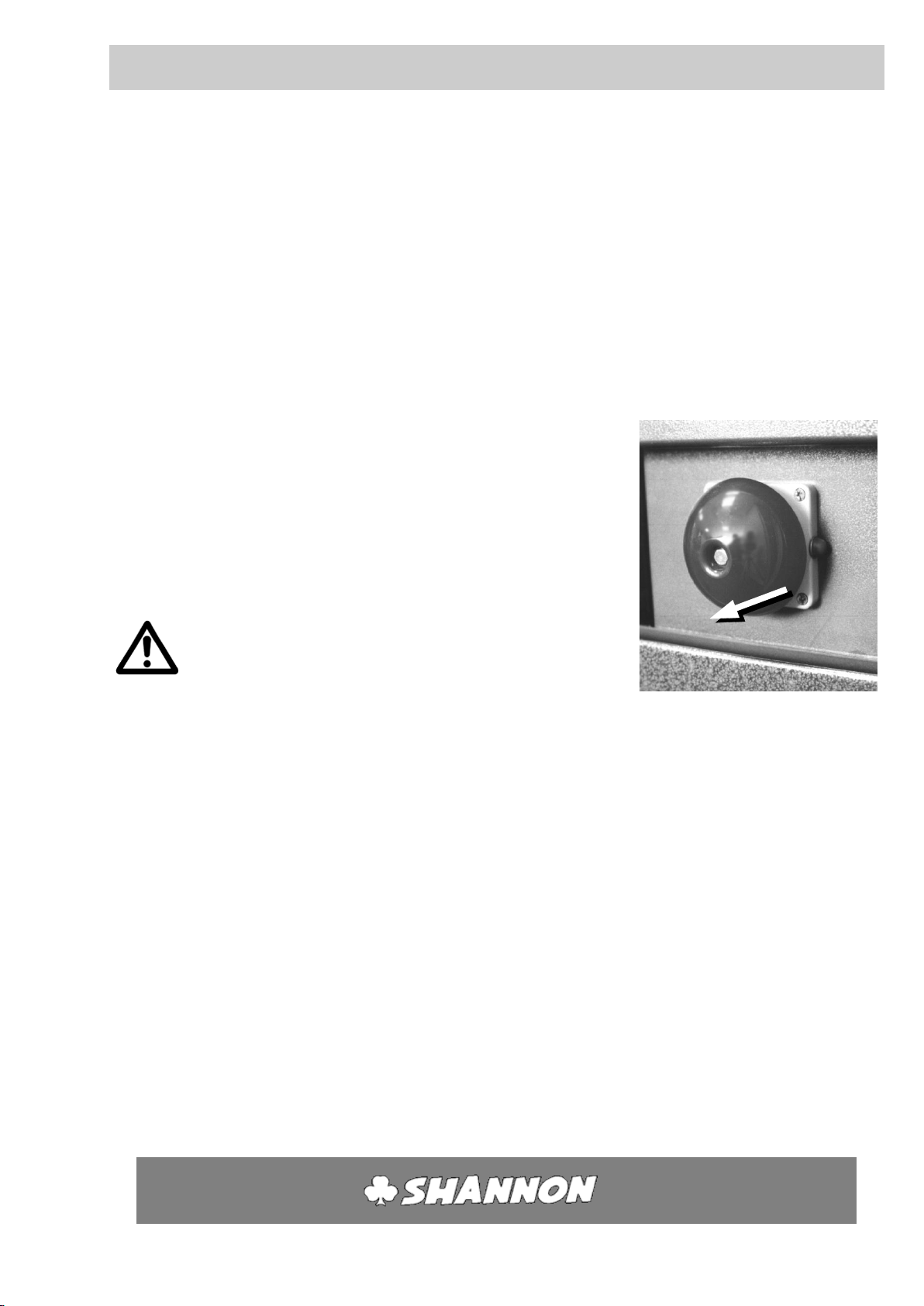
4.2 EMERGENCY STOP
There is an emergency stop button at the front of the machine
on the left and right, which can be reached by the operator
from the normal working position. The pedal switch has also an
emergency stop function, when it is pushed in completely. By
using the emergency steps the electrical power of the
regulating units, will be disconnected and the top frame lifts up.
(see also § 5.2)
Only use the emergency stop buttons in the following
situations:
Risk of trapped limbs.
Defects in the timer, so the machine fails to open after the
pre-set time.
An outbreak of fire or situations involving a risk of fire.
Any situation which might present a risk to people or
animals.
Any other situation, which might present a risk or cause,
damage to the machine and/or objects.
When the emergency situation has been remedied, the
emergency stop button must be reset and the various functions
switched on again individually.
Pulling it out until a click is heard resets the emergency stop
button. Pushing the blue button, which is mounted, on the
pedal switch will reset the food pedal.
4.3 AIR PRESSURE MONITORING
The machine switches off if the air pressure fails.
The lamp in the main switch Aremains alight.
When the pressure is restored the top frame lifts up again. The
machine must then be started up again.
4
User’s guide
HRP/D
-11-
HS
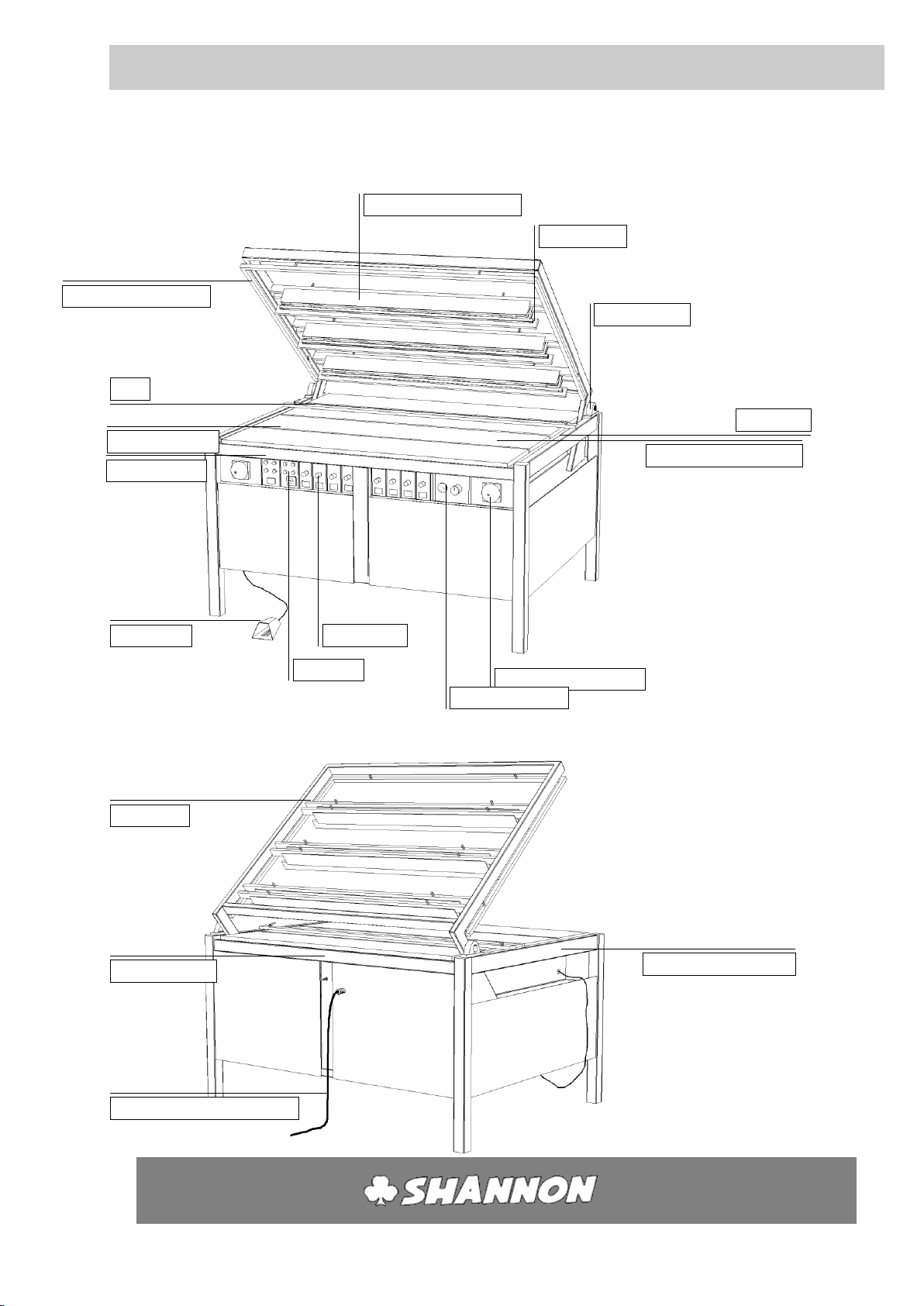
Legend
5.1 OVERVIEW
5
Top frame
Upper heating element
Pressure bar
Emergency top switch
Stop
Gradation
Emergency stop button
Foot switch
Switch unit
Timer unit
Control unit
Pressure regulator
Bearing block
Lower heating element
Working surface
Foot switch connection
Air connection
Power supply cable connection
User’s guide
HRP/D
-12-
HS
Legend 5
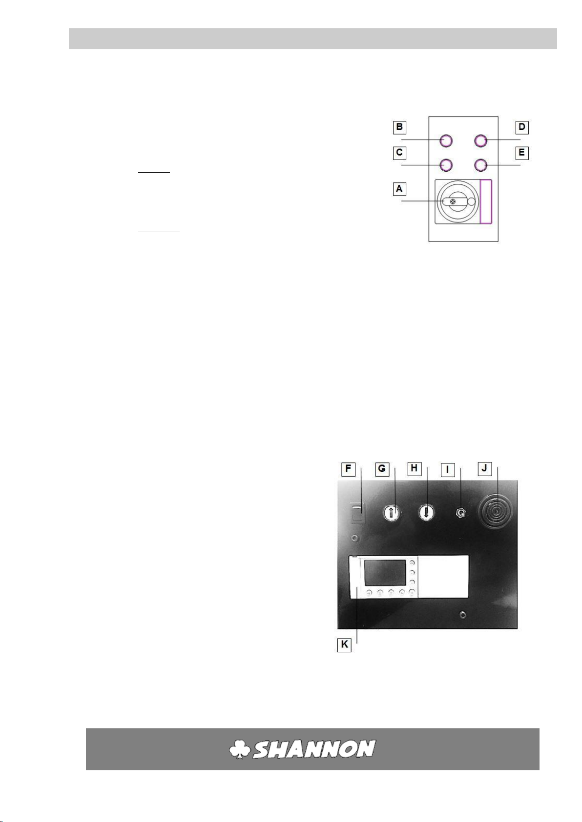
5.2 SWITCH UNIT
This contains the main switch (A) of the machine and the
push button switches to start the heating and the top frame.
AMain switch.
heating
BSwitch on control units (Also reset button for emergency
stop).
CSwitch off control units.
top frame
DSwitch on top frame.
ESwitch off top frame.
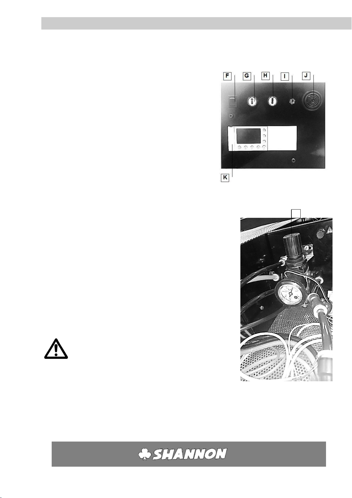
5.3 AIR/TIMER UNIT
The timer unit is the combined unit for operation of the top
frame (Gand H), operating the buzzer (Iand J) and setting the
cycle time (K). When the foot or push-button (H) switch is
operated, the machine closes. The counter begins to run when
the machine is fully closed, afterwards the switch can be
released. At the end of the pre-set time, the top frame opens
and the buzzer (J) makes a whistling sound for a few seconds.
This sound can be turned off by switch (I). The counter is then
returned to 0.
FSelector switch foot/hand operation.
GTop frame up.
HTop frame down.
IBuzzer on/off
JBuzzer
K Electronic timer.
User’s guide
HRP/D
-13-
HS
Legend 5
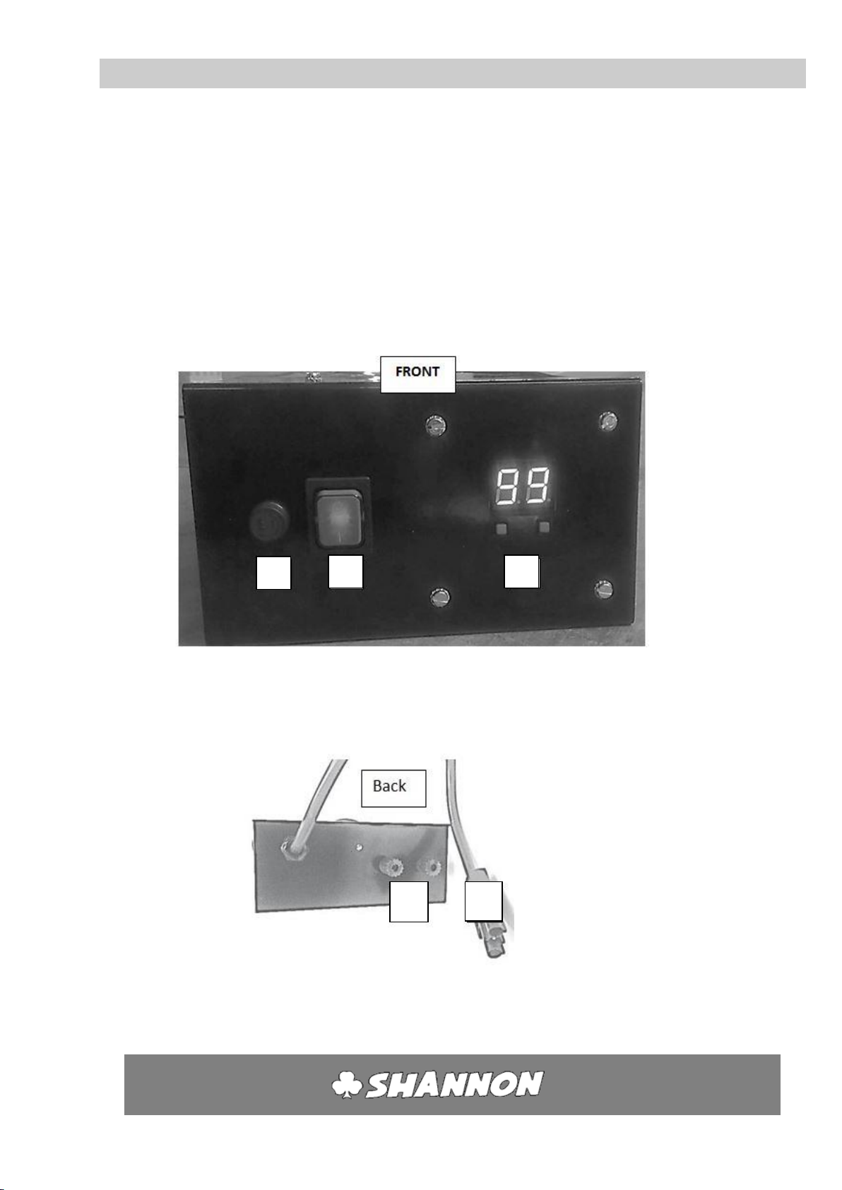
5.4 CONTROL UNITS
The control unit contains an electronic control with which the
temperature of a filament is set.
LSwitch on/off (green lamp).
M Temperature adjustment
NConnection to filaments
OConnection to 220V ACL
PFuse
L
O
N
M
P

User’s guide
HRP/D
-14-
HS
Installation
6.1 ASSEMBLY
1. Remove packaging and blocking of top frame.
2. Place the machine on a level floor with sufficient space
around and above the machine.
3. Level the working surface of the machine, using shims
under the feet if necessary.
4. Ensure there is adequate ventilation and lighting at the
workplace.
5. Avoid draughts, in order to prevent uneven heating.
When moving the machine with a forklift truck ensure that the
machine is supported right in the centre.
Also use sufficiently long prongs on the forklift truck.
6.2 CONNECTING COMPRESSED AIR
1. Check that all heating elements and pressure bars in the top
frame are firmly attached.
2. Check the air pressure in your system (max. 8 bar).
3. Close the reducing valve on the air unit (turn to the left).
Unlock if necessary (pull out).
4. Using a quick-action coupling connect the rear of the
machine to your compressed air system or compressor.
5. Slowly open the reducing valve (turn to the right) and set
the air pressure in the system at 6 bar.
6.3 CONNECTING POWER CABLE
1. Check that the rating of the electrical system is adequate (see technical data).
2. Check that the main switch Ais in the -position.
3. Plug in the machine.
6.4 CONNECTING FOOT SWITCH
1. Insert the plug of the foot switch into the connection on
the side of the machine. The plug will click into place.
N.B. To remove the foot switch the small stop above the
plug must be pressed.
6

User’s guide
HRP/D
-15-
HS
Operation
7.1 PREPARATION
1. Check that the air pressure is set at 6 Bar (see 7.8, page
16).
2. Clear the working surface.
3. Check that all the heating elements are connected to
the control units.
4. Check that no scraps of material remain in the
reflectors.
5. Check that all the upper heating elements and pressure
bars are firmly attached to the top frame.
6. Turn the potentiometers in the control units to "0".
7. Switch off all the control units (position "").
8. Turn on the main switch A(position I).
The red lamp in switch Cwill light.
The yellow lamp in switch Ewill light.
If switch Fis set to Hand Operation, the yellow lamp in
switch Hwill light.
7.2 SWITCHING ON CONTROL UNITS
The power supply to the control units must be switched on separately.
1. Press switch B.
The red lamp in switch Cwill go out.
The green lamp in switch Bwill light.
The control units are now ready for use!
7.3 SWITCHING ON TOP FRAME
The top frame is switched on separately. The safety system with the ribbon switch
must then be released.
1. Press switch D.
The yellow lamp in switch Ewill go out.
The green lamp in switch Dwill light.
7

User’s guide
HRP/D
-16-
HS
Operation 7
7.4 SWITCHING ON HEATING ELEMENTS
Each heating element can be switched on and controlled individually.
Switch on the desired control unit with switch (L). See 5.4.
7.5 SETTING THE TEMPERATURE
The temperature of the filament can be set using the temperature regulator.
1. When turning on the on/off switch, the display will show the value that was last
saved (keeping the machine on a certain value for >20 seconds will make it
remember this value).
2. Press the right button (arrow up) to increase the value, up to 99 (keeping this
pressed in will make the value cycle much faster)
3. Press the left button (arrow down) to decrease the value, down to 00 (keeping this
pressed in will make the value cycle much faster)
4. Press both buttons at the same time to go directly to 00. Doing this also resets the
machine.
7.6 TROUBLE SHOOTING
Error message
Meaning
Solution
E1
The wire is loose (not connected)
Turn off the machine, check the filament, and reset the
machine
(see §9.1 for changing filament)
Note: Between the values 00 and 04, this fault cannot be
detected
E2
The wire is loose (spark detection)
Check the connection of the filament
Check the filament, and reset the machine
This fault can also be reset by the arrow down button
(see §9.1 for changing filament)
E9
Broken circuit board
Contact the supplier for a new circuit board
Empty display
No power
Alert a maintenance engineer
Check the fuse (see §10.1)
Check the power supply cable
Contact the supplier if necessary
80
User’s guide
HRP/D
-17-
HS
Operation 7
7.7 SETTING CYCLE TIME
The time during which the machine is closed to heat
the plastic sheet on two sides is set using the
electronical timer K.
7.8 HAND OR FOOT OPERATION
Select hand or foot operation using switch F.
Position 1: Hand operation.
The frame closes when switch His
pressed.
Position 2: Foot operation.
The frame closes when the foot pedal is pressed.
Press switch G(arrow up) to open the machine before the end
of the set time. The timer (K) is returned to 0.
7.9 SET AIR PRESSURE
Control the pressure in the system with reducing valve M, which
can be found on the water separator (see 10.4, page 30). The air
pressure is set by the factory at 6 bar.
N.B. To right: valve open
To left: valve closed
press knob in: lock
pull knob out: unlock
Always lock the reducing valve when the air is being
disconnected from the machine.
7.10 RESET RIBBON SWITCH
When the ribbon switch is touched the machine opens immediately. It is then
impossible to close the machine with the foot switch or pressure switch H. The red
lamp Ewill light. Press switch Dto start the machine again. The green lamp in switch
Dwill light.
M
User’s guide
HRP/D
-18-
HS
Operation 7
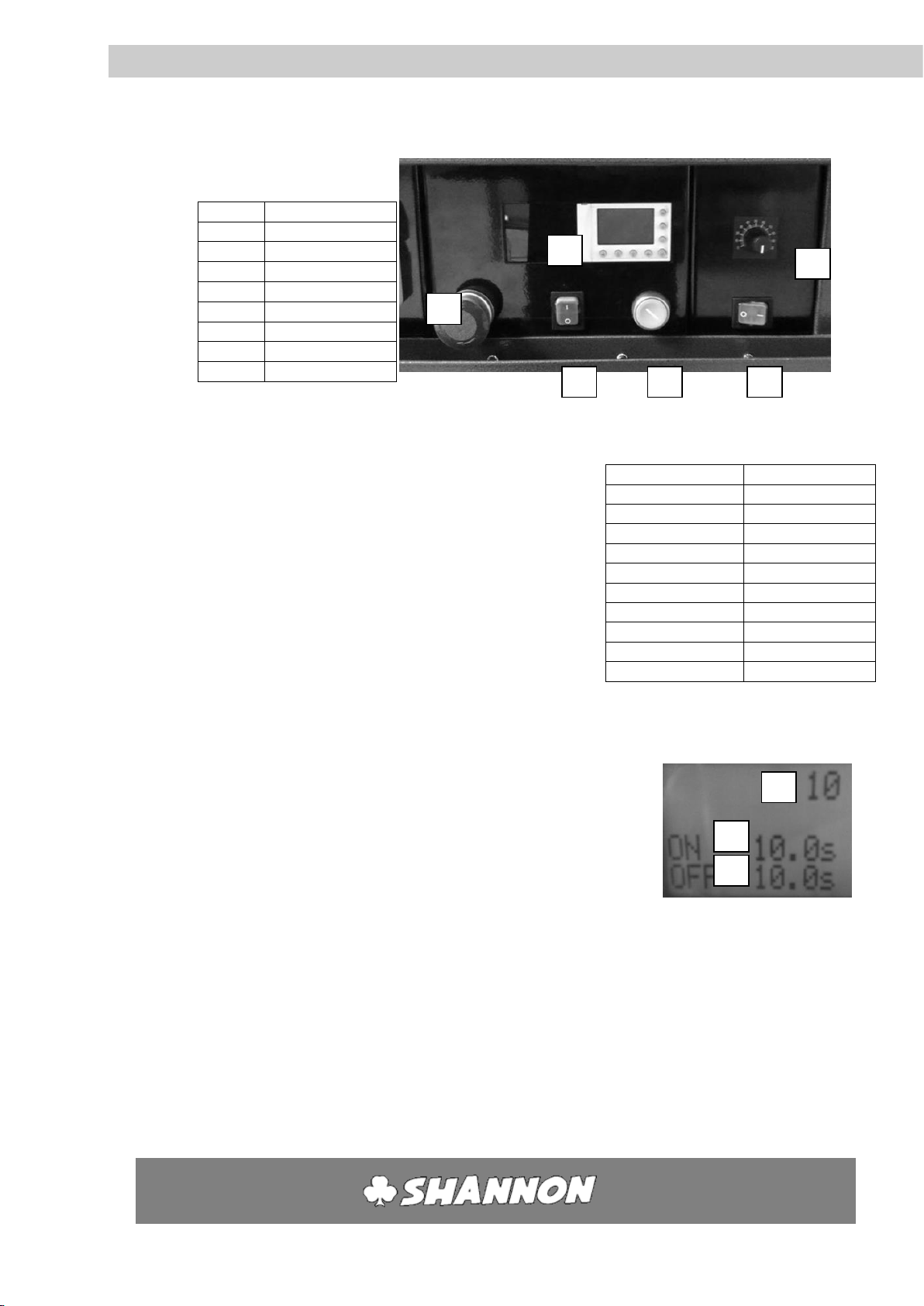
7.11 SWITCHING ON TRANSPORTSYSTEM
Display buttons[6]
Button
function
Esc
Cancel
+
Increase value
-
Decrease value
OK
Confirm
►
Move right
▼
Move down
▲
Move up
◄
Move left
Transport system:
Before using the transport system, first turn the speed
regulator[5] all the way to the left. To activate the
transport system, switch the green button[4] so that it
lights up. Then, turn the speed regulator[5] to regulate
the speed. On the right you’ll find a table which gives an
indication on how fast the track goes from 1 end of the
machine to the other, on each rotation of the knob.
Note: these times are an indication, and are not absolute.
Feeding system:
1. Press the left green button[2] so that it lights up. The control system
of the feeding system is now activated.
2. There are three numbers now on the display ranked
from top to bottom as:
a. [7] The number of cycles that the machine will
operate.
b. [8] The time in seconds that the pusher is
reloading a new piece of plastic.
c. [9] The time in seconds that the feeding system
is pushing a new piece of plastic.
3. For first time usage, set all the values on 10:
a. Swap between values by using the ▼/▲ buttons.
b. Increase of decrease the value by using +/-.
c. Cancel the value by using he “ESC” button.
d. Confirm the value by using the “OK” button.
Full knob rotation
Time (in seconds)
1
70
2
35
3
24
4
19
5
16
6
14
7
12.5
8
12
9
11.5
10
11
1
2
3
4
5
6
7
8
9

User’s guide
HRP/D
-19-
HS
Operation 7
4. Press the round red button[1] to stop the machine
5. Press the green round button[3] to active the pneumatics. The feeding
system will begin working now.
6. If the pusher has to wait between two cycles of pushing plates on the
belt, it can best be done by pausing the pusher beneath the stack of
plates. The system has to be tuned in such a way that if the pusher
comes from underneath the stack of plates, it has to begin pushing
immediately.
7. The feeding system can be fine-tuned un the following ways:
a. If the system stops to fast, increase the cycle number by
increasing the top value in the display.
b. If the reloading time is too long, decrease the second value on
the display.
c. If the pushing time is too long, decrease the third value on the
display.
Table of contents
Other Shannon Cutter manuals

Shannon
Shannon HRP/S User manual

Shannon
Shannon HRK 65 User manual

Shannon
Shannon ABM-D 135 User manual

Shannon
Shannon AFF/D 135 User manual

Shannon
Shannon HRT 220 User manual

Shannon
Shannon HRT 65 User manual

Shannon
Shannon HRT/D 300 User manual

Shannon
Shannon HR 220-300 User manual

Shannon
Shannon HRP 220 User manual


