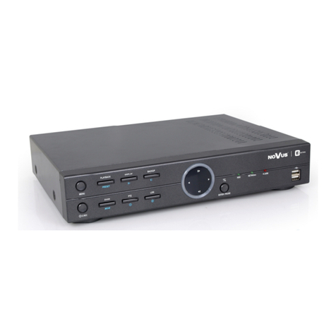
Novus NDR-EA3104M User manual

NDR-EA3104M
U s e r ’s m a n u a l

NDR-EA3104M User’s manual - 1.0 version
All rights reserved © AA Holding sp. z o.o.
2
EMC (2004/108/EC) and LVD (2006/95/EC ) Directives
CE Marking
O r prod cts are man fact red to comply with req irements of following directives and
national reg lations implementing the directives:
• Electromagnetic compatibility EMC 2004/108/EC.
• Low voltage LVD 2006/95/EC with f rther amendment. The Directive applies to electrical
eq ipment designed for se with a voltage rating of between 50VAC and 1000VAC as well
as 75VDC and 1500VDC.
WEEE Directive 2002/96/EC
Information on Disposal for Users of Waste Electrical and Electronic Equipment
This appliance is marked according to the E ropean Directive on Waste Electrical and
Electronic Eq ipment (2002/96/EC) and f rther amendments. By ens ring this prod ct is disposed of
correctly, yo will help to prevent potential negative conseq ences for the environment and h man
health, which co ld otherwise be ca sed by inappropriate waste handling of this prod ct.
The symbol on the prod ct, or the doc ments accompanying the prod ct, indicates that this appliance
may not be treated as ho sehold waste. It shall be handed over to the applicable collection point for the
waste electrical and electronic eq ipment for recycling p rpose. For more information abo t recycling
of this prod ct, please contact yo r local a thorities, yo r ho sehold waste disposal service or the shop
where yo p rchased the prod ct.
RoH Directive 2002/95/EC
Concerning for h man health protection and friendly environment, we ass re that o r
prod cts falling nder RoHS Directive reg lations, regarding the restriction of the se of hazardo s
s bstances in electrical and electronic eq ipment, were designed and man fact red in compliance with
mentioned reg lation. Sim ltaneo sly, we claim that o r prod cts were tested and do not contain
hazardo s s bstances exceeding limits which co ld have negative impact on h man health or nat ral
environment.
Information
The device, as a part of professional CCTV system sed for s rveillance and control, is not designed
for self installation in ho seholds by individ als witho t technical knowledge.
The man fact rer is not responsible for defects and damages res lted from improper or inconsistent
with ser’s man al installation of the device in the system.
COMMENT AND WARNING

NDR-EA3104M User’s manual - 1.0 version
All rights reserved © AA Holding sp. z o.o.
3
AFETY REQUIREMENT
ATTENTION!
PRIOR TO UNDERTAKING ANY ACTION THAT IS NOT PROVIDED FOR THE GIVEN
PRODUCT IN ITS USER’S MANUAL AND OTHER DOCUMENTS DELIVERED WITH THE
PRODUCT, OR THAT ARISES FROM THE NORMAL APPLICATION OF THE PRODUCT, ITS
MANUFACTURER MUST BE CONTACTED OR THE RESPONSIBILITY OF THE
MANUFACTURER FOR THE RESULTS OF SUCH AN ACTION SHALL BE EXCLUDED.
1. The installation of NDR-EA3104M DVR sho ld be made by a q alified service person or a
professional safety system installer.
2. Recorders m stn’t be placed in places where ventilating holes are partially or f lly covered.
3. User’s interference inside the device is not allowed and is nnecessary as it does not have any
systems which req ire adj sting or which are s itable for self-repair. Yo m stn’t dismantle the
recorder or remove any single fastening screws. If any repairs are necessary contact the service.
The device m st be take care of and protected against any mechanical damage.
4. The recorder has to be protected against h midity and d st. In case the recorder had a contact with
water react immediately: switch off the power s pply and contact the a thorised Nov s service. If
the device gets dirty it might get damaged or electroc te someone.
5. The device can only be cleaned with a damp cloth after the power s pply has been switched off.
Avoid strong detergents (liq ids and sprays). Mild detergents can be sed if the recorder becomes
very dirty.
6. Power s pply nit cords and signal cords sho ld be laid in a way that eliminates the risk of
mechanical damage; special attention sho ld be paid to the pl g. Be caref l not to overload sockets
and extension cords so that there is no fire.
7. To avoid recorder’s damage vision and control signals sho ld be eq ipped with systems protecting
against dist rbances, over voltage and atmospheric discharge that are in compliance with Polish
reg lations. It is also advised to se gro nd loop isolators.
8. The device m stn’t be sed in conditions which do not f lfil operating req irements as far as power
s pply, relative h midity or air temperat re are concerned.
9. Yo cannot allow any metal objects get inside the recorder. It might ca se serio s damage. If a
metal object gets inside the device contact the a thorised Nov s service immediately.
10. The man fact rer does not bear responsibility for damage or loss of data stored on HDDs or other
media occ rred d ring the sage of the prod ct.

NDR-EA3104M User’s manual - 1.0 version
All rights reserved © AA Holding sp. z o.o.
4
1. FOREWORD INFORMATION
1.1. Main characteristics
• QUADRUPLEX: sim ltaneo s recording, live monitoring/playback, back p and networking
• Operating system based on Lin x
• Real-time display
• Recording speed: p to 100 fps
• H.264 compression
• Recording resol tion:
- 720 x 576
- 720 x 288
- 360 x 288
• S pports 1 2,5” SATA HDD (installed in the swappable bay), 1 HDD 250 GB in-set incl ded
• S pports 1 SD card
• Recording speed and q ality defined individ ally for each camera
• Advanced sched le recording & motion detection f nctions
• Pre- & post-alarm f nctions
• Recording time estimation f nction
• 4 channel real-time a dio recording
• B ilt-in GPS receiver (antenna in-set incl ded)
• B ilt-in G-sensor
• External devices s pport (“Text-in” feat re): ATM, POS, AC etc.
• Advanced search f nctions of recorded images
• PTZ control directly from the device or thro gh the network
• Protocols: N-Control, Pelco-D, Pelco-P and others
• NV-KBD70 & NV-KBD30 keyboards compatible
• Back p: onto HDD or USB Flash Memory thro gh USB port & thro gh the network
• Networking (sim ltaneo s connections with m ltiple DVRs and alarm e-mail notification)
• Software: E-Viewer application for remote administration, live monitoring and recorded data search with
a b ilt-in mod le for graphical object vis alization (maps) and callback mod le E-Viewer Callback
• iMon software enabling remote administration, alarm management, receiving callbacks for iPhone and
Android-OS installed devices.
• Self-diagnostic f nctions with a tomatic notification
• User friendly m lti-ling al OSD
• Covert camera f nction
• IR remote control (in-set incl ded) and PC mo se control
• Vibration and mechanical shock protection
• Power o tp t: 12 VDC o tp t for 4 cameras and 1 monitor (max. 1.6 A)
• Power s pply: 12 ~ 36 VDC
* The list of recommended disk and memory cards models and their capacity is available on Nov s Sec rity website in the Compatible Disks file in the
prod ct tab
FOREWORD INFORMATION

NDR-EA3104M User’s manual - 1.0 version
All rights reserved © AA Holding sp. z o.o.
5
FOREWORD INFORMATION
1.2. NDR-EA3104M recorder’s technical data
Model NDR-EA3104M
Operation Mode QUADRUPLEX
Operating System Lin x
Video Inp t 4 x BNC
Video O tp t Main Monitor (1 x CVBS)
Power O tp t 5 x 12 VDC (for 4 cameras and 1 monitor - max. 1.6 A)
Alarm Inp t 2
Alarm O tp t 2 relay o tp ts
A dio Inp t 4 x Mic-in
A dio O tp t 1
GPS Antenna Inp t 1 x SMA type
Recording Speed
Up to 100 fps (360 x 288),
p to 50 fps (720 x 288),
p to 25 fps (720 x 576)
Compression H.264
Recording Resol tion 720 x 576, 720 x 288, 360 x 288
Recording Mode Time-lapse, Event (Alarm, Motion detection, G-Sensor, Video Loss and/or “Text-in”)
Display Speed 100 fps (real-time)
Display Screen F ll screen, 4, PiP, seq ence, ser defined, digital zoom of a chosen screen area: 2x,
freeze image f nction
Motion Detection 720 detection windows (30x24 grid) with sensitivity defined individ ally for each channel
Video Loss Detection Yes
Sched le Recording Individ ally adj stable for each day/specific days (holidays etc.) per camera,
combination of individ al recording modes possibility
Recorded Data Search By date/time, events, “Text-in”
Event History Log Up to 10 000 alarm events
Time Synchronization A tomatic time synchronization with NTP server
System Diagnostic A tomatic control of HDD bad sectors n mber (“Health”) & temperat re stat s
with local and network notification f nction
Storage S pports p to 1 2,5”SATA HDDs* and 1 SD card* (installed in the swappable bay), 1 HDD 250 GB
in-set incl ded
Back p Onto HDD or USB Flash Memory thro gh USB port, thro gh the network
External Ports
1 x Ethernet - RJ-45 interface, 10/100 Mbits/s,
1 x USB 2.0 for external drives (HDD, Flash Memory),
1 x USB 1.1 for PC mo se,
1 x RS-485 & 1 x RS-232 for PTZ cameras, NV-KBD70 & NV-KBD30 keyboards and for POS, ATM,
AC etc.,
1 x external GPS antenna (SMA type)
PTZ Control Directly from the device or thro gh the network
Protocol N-Control, Pelco-D, Pelco-P and others
Control IR remote controller (in-set incl ded), Network (E-Viewer, IE, iMon),
NV-KBD70 & NV-KBD30 keyboards, USB PC mo se
NDR-EA3104M User’s manual - 1.0 version
All rights reserved © AA Holding sp. z o.o.
6
FOREWORD INFORMATION
Set- p M lti-ling al On Screen Display (OSD)
Software E-Viewer
User A thorization Creation of ser gro ps and acco nts with diverse grants, password protection
A to System Recovery Hardware WATCHDOG f nction
Power S pply 12 ~ 36 VDC
Power Cons mption Approx. 64 W
Operating Temperat re -20°C ~ 40°C**
Relative H midity 0% ~ 80% (non-condensing)
Dimensions (mm) 218 (W) x 56 (H) x 255 (D)
Weight 1.33 kg (witho t HDD)
* The list of recommended disk and memory cards models and their capacity is available on Nov s
Sec rity website in the Compatible Disks file in the prod ct tab
** In case of low ambient temperat res, recording is performed on an SD card ntil proper hard drive
temperat re is reached.

NDR-EA3104M User’s manual - 1.0 version
All rights reserved © AA Holding sp. z o.o.
7
2. TARTING THE DEVICE
2.1 HDD installation
NDR-EA3104M DVRs feat re single SATA HDD. By factory defa lt, DVR feat res one 250GB
HDD. The list of compatible models and capacities is available in the „Compatible disks” attachment
nder a prod ct tab at the www.nov scctv.pl website.
In order to s ccessf lly mo nt an HDD please follow the instr ctions below:
- Open the HDD bay cover;
- Remove the HDD bay
- Unscrew 2 screws mo nting rear part of the HDD bay (with a b ilt-in fan)
- P ll o t the PCB/HDD board, npl g the fan
- Unpl g the SATA and HDD power cables
- Unscrew 4 HDD mo nting screws
- Remove the disk, replace it with a new one, screw it on, connect cables and screw the
cover.
Note: In order to obtain info on latest compatible D cards/HDDs together with their
capacities, please contact your distributor or visit www.novuscctv.com website. AAT
HOLDING company does not bear responsibility for any issues arising from usage of
unsupported D cards/HDDs.
Note: List of compatible HDDs contains all disks supported by a given DVR model,
including desktop HDDs. However due to the fact that image recording prefers
reliability usage of 24x7 recording HDDs is therefore advised.
Note: If a disk was used in another device, formatting becomes necessary Please take it into
account due to the irrecoverable data loss.
Note: Removing the HDD or SD card is permitted only after powering the device off or after opening
the cover which switches the DVR into idle state (indicated by solid bl e LED light and blinking green
LED), allowing to remove the bay. Removing prior to the occ rrence of described conditions may
res lt in serio s device damage, not q alifying for service repair!
HDD IN TALLATION

NDR-EA3104M User’s manual - 1.0 version
All rights reserved © AA Holding sp. z o.o.
8
2.2. Getting the device ready to work
Unpack the device caref lly.
After npacking, please ens re that package contains the following items:
If any of the elements has been damaged d ring transport, pack all the elements back into the original
packaging and contact yo r s pplier.
CAUTION!
• If the device was brought from a location with lower temperature, please wait until it
reaches the temperature of location it is currently in. Turning the device on immediately
after bringing it from a location with lower ambient temperature is forbidden, as the
condensing water vapour may cause short-circuits and damage the device as a result.
• Please get familiarized with description and functions of rear panel inputs.
• The manufacturer reserves the right to modify device’s parameters without notice. All the
data included in this manual are up to date at the moment of printing this manual.
TARTING THE DEVICE
IR remote controller
NDR-EA3104M recorder
User’s man al
GPS antenna Swappable hard drive bay key
and mo nting screws
Terminal block and connection cables
CD with a f ll version of ser’s
man al and software tools
and software

NDR-EA3104M User’s manual - 1.0 version
All rights reserved © AA Holding sp. z o.o.
9
TARTING THE DEVICE
1. FAN: Fan cooling the DVR or heating it (by distrib ting warm air from internal
heater) d ring start and operation in low temperat res. Do not cover!
2. MONITOR OUT: Main monitor connector, Composite Video Signal. Contains video and
a dio o tp ts, main monitor 12V DC power s pply and common gro nd for wires in the cable.
Switching between vario s display modes is possible. A dio o tp t doesn’t feat re the pre-
amplifier, therefore sage of speakers with b ilt-in pre-amplifiers is recommended.
CAUTION!
Maxim m c rrent for Monitor O t and Cameras Power O t is 1.6A
3. AV IN/: back panel connector. Please se the incl ded cable (depicted below) to
CAM POWER OUT connect it to the DVR:
4. GPS ANT.: external GPS antenna connector (SMA type)
5. RESET: maintenance only
2.3. Electrical connections and other back panel elements of the NDR-EA3104M recorder
NDR-EA3104M view (with back panel removed)
1
2
3
4
5
6
7
8
9
10
11
Gro nd
CVS Video o tp t
A dio o tp t
Main monitor 12 VDC o tp t
Not sed
Not sed

NDR-EA3104M User’s manual - 1.0 version
All rights reserved © AA Holding sp. z o.o.
10
TARTING THE DEVICE
6. DC 12~36 V: power s pply connector (12 ~36VDC)
Please se the following cable to connect power s pply:
7. NETWORK: RJ-45 network socket (10/100Mb/s)
8. EN OR: 2 alarm inp ts, which may operate either in normal open (N.O.) or normal
closed (N.C.) mode. In order to detect the alarm signal it sho ld last at least
0.5sec. Sensor inp t is designed as a clamp terminal.
9. ALARM OUT: the DVR is capable of activating external devices s ch as b zzers, metal
halide lamps, sirens etc. via its 2 relay alarm o tp ts which may operate
either in normal open (N.O.) or normal closed (N.C.) mode. Alarm o tp t
is designed as a clamp terminal.
Max. load capacity of the o tp ts is 0,17A/60VAC.
10. R 232: RS-232 connector for NVB-KBD70 & NVB-KBD30 system keyboards,
devices generating information in the form of ASCII code (cash registers,
ATMs, etc.). Designed as a clamp terminal.
Note:
RS-232 port may perform only one of the f nctions mentioned above at a
time.
11. RS485: RS-485 clamp terminal for remote control of speed dome cameras,
NVB-KBD70 & NVB-KBD30 system keyboards or devices generating
information in the form of ASCII code (cash registers, ATMs etc.).
CAUTION!
RS-485 port may perform only one of the f nctions mentioned above at a
time.
Gro nd (
-)
DC 12~36 V connected
directly to the battery (
+)
Ignition power wire (
+)
ACC-IN
DC 12~36 V connected
directly to the battery (
+)

NDR-EA3104M User’s manual - 1.0 version
All rights reserved © AA Holding sp. z o.o.
11
12. AUDIO IN: 4 a dio mono inp ts (RCA type) for connecting microphones via
preamplifier. Part of a terminal block .
CAUTION!
So nd recording may be cond cted only when legal reg lations of a given
co ntry allow for s ch activities.
13. CAM POWER : 12 VDC o tp t allows to power p the cameras. Part of a terminal block
OUT
CAUTION!
Maxim m c rrent for Monitor Out and Cam Power Out is 1.6A
14. VIDEO IN: 4 video inp ts (BNC type) for connecting video signal so rces to the DVR
15. Hole in the casing easing attachment of cables to the device
16. Ventilation hole, do not cover!
CAUTION!
Due to the fact that particular DVR inputs/outputs are made in the form of wires (cables) device
installation requires additional tools, e.g. soldering iron, connectors, heat shrink sleeves etc.
Detailed information about each connection can be found on the following pages of this manual.
TARTING THE DEVICE
13
12
14
15
16
VIDEO IN
NDR-EA3104M view (back panel attached)

NDR-EA3104M User’s manual - 1.0 version
All rights reserved © AA Holding sp. z o.o.
12
1. U B: USB 2.0 port for connecting external HDDs or Flash memory. Maxim m
cable length connecting port to a device sho ldn't exceed 30 cm.
2. IR DETECTOR IR remote control receiver.
3. HDD Key lock for swappable hard drive bay and SD card socket
KEY LOCK Unlocking the lid allows n-mo nting hard drive bay and SD card from
DVR. Hard drive bay may be then connected directly to PC via Mini-B USB
cable (not incl ded).
Note:
For safety reasons, please t rn off the DVR prior to removing hard drive
bay or SD card. Removing hard drive bay or SD card d ring normal DVR
operation is also possible. Please open HDD key lock and wait for abo t 10
second ntil green LED starts blinking, indicating that storage device can
be removed safely.
Removing the storage device before events described above take place
is prohibited, as it may cause damage to the device not qualifying for
service repair!
4. LED: Flickering green HDD LED indicates that the recording or search/
- GREEN playback f nctions are active.
Reg larly blinking green LED indicates that HDD key lock is opened and
storage devices may be removed safely.
- RED Solid red ALARM LED means that alarm event occ rred (e.g. loss of video
signal) and at least one of the alarm o tp ts or b zzer is active. ALARM
LED blinking reg larly indicates working internal heater, raising t h e
temperat re to s fficient level for the device to start p.
- BLUE Solid bl e DVR LED means that power s pply is connected.
TARTING THE DEVICE
2.4. Front panel description
NDR-EA3104M view
1
2
3
5
4
7
8
6

NDR-EA3104M User’s manual - 1.0 version
All rights reserved © AA Holding sp. z o.o.
13
TARTING THE DEVICE
5. U B USB 1.1 port for USB mo se connection
6. LED: With swappable bay lid opened, additional LEDs become visible:
- GREEN Blinking green LED indicates that the recording or
searching / playback is in progress.
- BLUE Solid bl e DVR LED means that swappable hard drive bay is properly
connected .
Note:
Removing storage devices is possible only when both LEDs are dark.
7. D CARD: SD/SSD card slot visible when swappable bay lid is opened. D ring low
temperat re start p proced re internal hard drive cannot be sed. U n til
temperat re reaches acceptable level, recordings are stored on SD/SSD
card. Data stored there are later moved to internal hard drive.
CAUTION!
If SD/SSD card is not present, recording process starts only when
s fficient HDD operating temperat res has been reached.
Depending on temperat re level, heating process can take from a few to
more than a dozen min tes.
8. Mini U B: Mini USB socket visible on the swappable bay, after opening the lid.
Allows to connect the bay directly to a PC comp ter in order to
play/copy the recordings stored on the DVR’s HDD.
2.6. Controlling via IR remote controller
The set incl des an IR remote controller. Its range depends on battery stat s and may vary between
a few and few tens of meters. Single remote may control p to 99 DVRs. If an ID n mber of the
device eq als 0, the IR remote control of that device is possible instantly, witho t any additional
set p (f rthermore, sim ltaneo s controlling of few DVRs with the same remote is possible).
To s ccessf lly control a DVR with its ID eq al 1~99, please press ID b tton first. An ID selection
men appears on the DVR screen. Please enter appropriate ID n mber in the Controller ID field,
corresponding to the ID set in the DVR. Confirm by pressing OK.
NDR-EA3104M Remote controller overview

NDR-EA3104M User’s manual - 1.0 version
All rights reserved © AA Holding sp. z o.o.
14
2.2. Installation of the device
Design of the device provides protection against mechanical shocks and vibration. Thanks to that,
mo nting and operating the device in cars, b ses, vans etc. is safe and possible.
CAUTION!
Please provide a flat and stable s rface for DVR installation.
In order to properly mo nt the DVR, please follow the instr ctions below:
• nscrew the 6 screws attaching mo nting base plate to the DVR and disconnect the cable
connecting back panel with the DVR (if needed)
TARTING THE DEVICE
Chassis dimensions

NDR-EA3104M User’s manual - 1.0 version
All rights reserved © AA Holding sp. z o.o.
15
• mo nt the base plate to a s rface sing 6 incl ded screws
• mo nt DVR to the base plate (as depicted on previo s page)
• connect all necessary cables, taking the back panel presence into acco nt. Description of
connectors is presented f rther in this man al.
• mo nt the back panel to the device as depicted on previo s page
NOTE: Depending on the mo nting location ser sho ld make the appropriate settings in the EVENT
->G- ensor men .
TARTING THE DEVICE

NDR-EA3104M User’s manual - 1.0 version
All rights reserved © AA Holding sp. z o.o.
16
2.4. Connecting of peripheral equipment to NDR-EA4104M recorders
System connection sho ld be performed only by q alified personnel. Please familiarize yo rself with
the scheme located below, depicting possible implementation of the DVR in the system, before
installation.
Depending on req irements, each system will have different n mber of peripherals connected.
Monitors, cameras etc. sho ld be p rchased separately, depending on c rrent needs.
TARTING THE DEVICE

NDR-EA3104M User’s manual - 1.0 version
All rights reserved © AA Holding sp. z o.o.
17
2.4.1. Connecting power supply
2.4.2. Connecting monitor
CAUTION!
Maxim m c rrent for Monitor Out and Cam Power Out connectors is 1.6A
TARTING THE DEVICE

NDR-EA3104M User’s manual - 1.0 version
All rights reserved © AA Holding sp. z o.o.
18
2.4.3. Connecting cameras/microphones
CAUTION!
Maxim m c rrent for Monitor Out and Cam Power Out connectors is 1.6A
TARTING THE DEVICE

NDR-EA3104M User’s manual - 1.0 version
All rights reserved © AA Holding sp. z o.o.
19
2.7. Powering the device
Connecting power supply to the DVR starts its operation. ystem initialization takes up to 30s.
Please do not run any of the devices’ functions nor press any buttons. Turning the device off is
available via the menu or disconnecting the ACC-IN cable.
3. DVR O D MENU
Recorder feat res a m ltiling al OSD men allowing for adj sting the settings of the device. English,
Polish, Korean, panish, lovak, Czech, Turkish, Dutch, Russian, German, Portuguese, Italian,
French and Greek are available.
Prior to sing DVR for the first time, initial set p is strongly advised. This incl des setting s ch
parameters as time and date, lang age version, camera, a dio, remote control, record mode, network
and password.
Config ration described below is compliant with one performed via IR remote controller.
To enter DVR’s OSD men please press MENU/EXIT or select MENU from additional men visible
after pressing the ENTER b tton.
TARTING THE DEVICE

NDR-EA3104M User’s manual - 1.0 version
All rights reserved © AA Holding sp. z o.o.
20
RECORDER’ MENU
The Login screen, depicted below appears:
Select ID and enter the password by pressing the appropriate combination of channel n mber
b ttons or sing navigation b ttons, then confirm with OK.
There is no default password when logging in for the first time as the admin user! Please leave
the password field empty and select OK button.
Arrows are sed for moving aro nd the men :
- right, - left, - p, - down
To confirm selections, enter s b-men s and edit fields se the ENTER b tton
Val es may be also changed by sing the arrow b ttons.
To leave set p mode or to leave s b-men s and val e editing se the MENU/EXIT b tton.
To set the same val e for all fields available in one col mn highlight the desired col mn’s name with
the c rsor and enter the req ired val e.
A virt al keyboard is available whenever the need for entering names and titles arises. Use the arrow
keys to highlight the desired character and press ENTER b tton. The selected character appears in the
title bar and the c rsor moves to the next position. Pressing toggles between the pper and lower
case letters, serves as the backspace, and DEL deletes entered characters.
Table of contents
Languages:
Other Novus DVR manuals

Novus
Novus NV-DVR5009 User manual

Novus
Novus NDR-BA5104 User manual

Novus
Novus NHDR-4116-H2 User manual

Novus
Novus NVR-4416P16-H2/F User manual

Novus
Novus NVR-6332-H8 User manual

Novus
Novus NHDR-4M5304AHD User manual

Novus
Novus NMS NVR 7XE-4U User manual

Novus
Novus N Control 6000 User manual

Novus
Novus NVR-5609 User manual

Novus
Novus NV-DVR5108/DVD User manual

Novus
Novus NDR-BA5104 User manual

Novus
Novus NDR-EB2104 User manual

Novus
Novus NHDR-4M5308AHD User manual

Novus
Novus NHDR-3208AHD User manual

Novus
Novus NHDR-4M5316AHD User manual

Novus
Novus NDR-EA2416 User manual

Novus
Novus NDR-BA6104 User manual

Novus
Novus NHDR-4304AHD User manual

Novus
Novus NDR-HB4208 User manual

Novus
Novus NHDR-52**AHD User manual