Novy 7600.400 User manual

NL Installatievoorschriften p. 2
FR
Instructions
d’installation p. 3
DE Montageanleitung S. 4
EN
Installation
instructions p. 5
7600400 110063 MA1
Novy
7600400
n
✓Flat’line
7600/7602/7610/7612
NL
1 VOORSCHRIFTEN VOOR VEILIGHEID
EN MONTAGE
Meer informatie over de Novy producten, accessoires en
diensten kunt u vinden op internet:
− België: www.novy.be
− Nederland: www.novynederland.nl
Dit is de montage instructie voor het toestel zoals op de
voorzijde is aangegeven.
In deze montage instructie wordt gewerkt met een aantal
symbolen. Hieronder vind u de betekenis van deze symbolen.
Symbool Betekenis Actie
Indicatie Toelichting van een
indicatie op het toestel.
Info/
Waarschuwing
Dit symbool duidt op
een belangrijke tip of een
gevaarlijke situatie
Waarschuwing voorafgaand montage
−
Lees aandachtig de gebruiksaanwijzing en de monta-
geinstructie vóór de installatie en ingebruikname van
dit toestel. Hierin vind u belangrijke informatie voor de
montage en gebruik van het toestel.
−
Het toestel is uitsluitend bedoeld voor huishoudelijk ge-
bruik (bereiding van voedingsmiddelen) met uitsluiting
van alle ander huishoudelijk, commercieel of industrieel
gebruik. Gebruik het toestel niet buitenshuis.
− Bewaar deze handleiding zorgvuldig en geef deze door
aan de persoon die het toestel eventueel na u gebruikt.
−
Dit toestel voldoet aan de geldende veiligheidsvoor-
schriften. Ondeskundige montage kan echter persoonlijk
letsel en schade aan het toestel veroorzaken.
−
Controleer de staat van het toestel en het montage-
materiaal zodra u ze uit de verpakking haalt. Neem het
toestel met zorg uit de verpakking. Gebruik geen scherpe
messen om de verpakking te openen.
−
Installeer het toestel niet indien het beschadigd is en
richt u in dat geval tot Novy.
−
Controleer aan de hand van de tekening of alle mon-
tagematerialen meegeleverd zijn.
−
Novy is niet aansprakelijk voor schade als gevolg van
onjuiste montage, onjuiste aansluiting, onjuist gebruik
of onjuiste bediening.
− De veiligheid is alleen gewaarborgd bij een deskundige
montage volgens de montagehandleiding. De installa-
teur is verantwoordelijk voor een goede werking op de
plaats van opstelling.
−
Metalen onderdelen kunnen scherpe kantjes hebben
en u kunt zich eraan verwonden. Draag daarom bij het
monteren handschoenen die u daartegen beschermen.
− Het toestel niet ombouwen of wijzigen.
− Verwijder etiketten en zelfklevers/ stickers welke op het
toestel zijn geplaatst met gebruiks- of montage tips. In
het toestel achter het filter bevindt zich het type sticker,
deze niet verwijderen.
2 HET MONOBLOCK
RECIRCULATIEFILTER
Hedendaagse keukenventilatie en energie-efficiëntie:
de eerste kan niet zonder de laatste. Recirculatie biedt
hierin de oplossing. Recirculatieafzuigkappen voeren de
kookdampen niet af, maar filteren de geur en het vet uit
de lucht en blazen de gefilterde lucht vervolgens terug
de woning in.
Het Novy monoblockfilter absorbeert onaangename geuren
en maakt afvoer van warme lucht naar buiten toe overbodig.
De basis van het monoblockfilter is een vooruitstrevende
vorm van geactiveerde koolstofdeeltjes in de vorm van mi-
nuscule bolletjes die op een dragende labyrintstructuur zijn
gekleefd. Door de labyrintstructuur heeft het monoblockfilter
een beperkt verlies aan druk en een maximaal behoud
aan rendement. Dit resulteert in een efficiënte afzuiging,
uitstekende geurabsorptie en een beperkt geluidsniveau.
3 GEBRUIK VAN HET MONOBLOCK
FILTER
Het monoblock filter wordt toegepast in combinatie met
een dampkap/ afzuigkap of werkbladafzuiging.
Lees de gebruiksaanwijzing van uw toestel
voor de programmering en het gebruik van de
recirculatie modus.
Voor een optimale werking van het mono-
block recirculatiefilter is het van belang de
afzuiging van het toestel voor het koken aan
te zetten en de nalooptijd te respecteren.
Lees hiervoor de instructies in de gebruiks-
aanwijzing van uw toestel.
Zorg voor voldoende ventilatie in de keuken
voor een optimale efficiëntie van het recircu-
latie systeem.
Een indicatie op de afzuigkap of werkbladafzuiging geeft
aan dat het Monoblock recirculatiefilter vervangen dient
te worden.
De levensduur van deze Monoblock reciculatiefilter staat
vermeld op het label op de filter zelf.
xxxh
Een nieuw monoblock filter kunt u verkrijgen
via de vakhandel of via de Novy website.
Artikelnummer monoblock filter: 7600060.
2

FR
1 PRESCRIPTIONS DE SÉCURITÉ ET
D'INSTALLATION
Vous trouverez plus d'informations sur les produits, acces-
soires et services Novy sur Internet : www.novy.fr
Ceci est la notice de montage de l'appareil identifié en
première page.
Cette notice de montage utilise un certain nombre de
symboles. Vous trouverez ci-dessous la signification de
ces symboles.
Symbole Signification Action
Indication Explication d’une indi-
cation apparaissant sur
l’appareil
Avertissement Ce symbole signale un
conseil important ou une
situation dangereuse
Avertissements préalables au montage
− Veuillez lire attentivement le mode d’emploi et la notice
de montage avant d’installer et de mettre en service cet
appareil. Vous y trouverez des informations importantes
pour le montage et l’utilisation de l’appareil.
−
L’appareil est exclusivement destiné à un usage domes-
tique (préparation d’aliments), à l’exclusion de tout autre
usage domestique, commercial ou industriel. N’utilisez
pas l’appareil en extérieur.
−
Conservez soigneusement cette notice et remettez-le
à la personne qui pourrait utiliser l’appareil après vous.
−
Cet appareil est conforme aux règles de sécurité en vigueur.
Toutefois, une utilisation non conforme peut entraîner
des blessures corporelles et endommager l’appareil.
−
Vérifiez l’état de l’appareil et du matériel de montage dès
que vous les sortez de l’emballage. Retirez l’appareil de
l’emballage avec précaution. N’utilisez pas de couteaux
pointus pour ouvrir l’emballage.
− Si l’appareil est endommagé, ne l’installez pas et con-
tactez Novy.
− Vérifiez sur que tout le matériel de montage est inclus.
−
Novy n’est pas responsable des dommages résultant
d’un montage, d’un raccordement, d’une utilisation ou
d’un maniement incorrects.
−
La sécurité n’est garantie que si l’appareil est correc-
tement installé conformément à la notice de montage.
L’installateur est responsable du bon fonctionnement
sur le lieu d’installation.
−
Les pièces métalliques peuvent présenter des arêtes vives
et peuvent occasionner des blessures. Dès lors, portez
des gants qui vous en préservent lors de l’assemblage.
− Ne pas transformer ni modifier l’appareil.
−
Retirez les étiquettes et les autocollants qui ont été apposés
sur l’appareil et mentionnant des conseils d’utilisation
ou de montage. L’étiquette d’identification se trouve à
l’intérieur de l’appareil, derrière le filtre ; ne la retirez pas.
2 LE FILTRE DE RECIRCULATION
MONOBLOCK
Ventilation de la cuisine et efficacité énergétique : la première
ne peut pas se passer de l’autre. La recirculation offre la
meilleure solution. Les hottes d’aspiration à recirculation
n’évacuent pas les vapeurs de cuisson, elles filtrent les
odeurs et la graisse de l’air et ramènent l’air filtré dans
l’appartement.
Le filtre Novy monoblock absorbe les odeurs désagréables
et rend l’évacuation de l’air chaud vers l’extérieur super-
flue. La base du filtre monoblock est une forme avancée
de particules de carbone activées sous forme de billes
minuscules collées sur une structure de support en forme
de labyrinthe. À cause de cette structure de labyrinthe,
le filtre monoblock a une perte de pression limitée et un
contenu maximum de rendement. Cela résulte en une
aspiration efficace, une excellente absorption des odeurs
et un niveau sonore limité.
3 UTILISATION DU FILTRE
RECIRCULATION MONOBLOC
Le filtre monobloc est utilisé en combinaison avec une
hotte aspirante de cuisine ou de plan de travail.
Avant de programmer et d’utiliser le mode de
recirculation, lisez le manuel d’instructions de
votre appareil.
Pour un fonctionnement optimal du filtre de
recirculation monobloc, il est important de
mettre l’extracteur en marche avant la cuis-
son et de respecter le temps de fonctionne-
ment après la cuisson. Pour ce faire, lisez les
instructions figurant dans le mode d’emploi
de votre appareil.
Assurer une ventilation adéquate dans la cui-
sine pour une efficacité optimale du système
de recyclage.
Une indication sur la hotte aspirante ou la hotte de plan
de travail indique que le filtre à recirculation Monoblock
doit être remplacé.
La durée de vie de ce filtre à recirculation Monoblock est
indiquée sur l’étiquette apposée sur le filtre lui-même.
xxxh
Un nouveau filtre monoblock peut être obtenu
via le ou via le site Internet de Novy. Numéro
d’article filtre monoblock : 7600060.
3
DE
1 SICHERHEITS- UND
MONTAGEVORSCHRIFTEN
Weitere Informationen zu den Produkten, dem Zubehör
und den Dienstleistungen von Novy finden Sie im Internet
unter: www.novy-dunsthauben.de
Diese Broschüre enthält die Montageanleitung für das
Gerät, wie auf der Vorderseite angegeben.
In dieser Montageanleitung werden einige Symbole verwen-
det. Nachfolgend finden Sie eine Erklärung dieser Symbole.
Symbol Bedeutung Aktion
Anzeige Erläuterung einer Anzeige auf
dem Gerät
Warnhin-
weis
Dieses Symbol weist auf
einen wichtigen Tipp oder
eine gefährliche Situation hin.
Warnhinweise vor der montage
−
Lesen Sie die Gebrauchsanweisung und Montageanleitung
sorgfältig durch, bevor Sie dieses Gerät installieren und
in Betrieb nehmen. Darin sind wichtige Informationen in
Bezug auf die Installation und Verwendung des Geräts
enthalten.
−
Das Gerät ist nur für den Hausgebrauch (Zubereitung von
Lebensmitteln) bestimmt, unter Ausschluss aller anderen
haushaltlichen, gewerblichen und industriellen Zwecke.
Das Gerät darf nicht im Freien verwendet werden.
− Bewahren Sie diese Anleitung sorgfältig auf und geben
Sie sie an die Person weiter, die das Gerät möglicher-
weise nach Ihnen benutzt.
−
Dieses Gerät erfüllt die geltenden Sicherheitsvorschriften.
Eine unsachgemäße Montage kann jedoch zu Verletzun-
gen und Schäden am Gerät führen.
− Überprüfen Sie den Zustand des Geräts und des Mon-
tagematerials, sobald Sie es aus der Verpackung nehmen.
Nehmen Sie das Gerät sorgfältig aus der Verpackung.
Verwenden Sie zum Öffnen der Verpackung keine schar-
fen Messer.
−
Installieren Sie das Gerät nicht, wenn es beschädigt ist,
und wenden Sie sich in diesem Fall an Novy.
−
Überprüfen Sie anhand der Zeichnung, ob alle Mon-
tagematerialien vorhanden sind.
− Novy haftet nicht für Schäden, die durch falsche Mon-
tage, falschen Anschluss, unsachgemäße Verwendung
oder falsche Bedienung entstehen.
−
Die Sicherheit ist nur bei fachgerechter Installation gemäß
der Montageanleitung gewährleistet. Derjenige, der das
Gerät installiert, ist für den ordnungsgemäßen Betrieb
am Installationsort verantwortlich.
− Metallteile können scharfe Kanten haben, an denen Sie
sich verletzen können. Tragen Sie bei der Montage Hand-
schuhe, die Sie vor Verletzungen schützen.
− Das Gerät darf nicht umgebaut oder verändert werden.
− Entfernen Sie Etiketten und Aufkleber von dem Gerät,
die mit Verwendungs- oder Montagetipps versehen sind.
Hinter dem Fettfilter befindet sich ein Aufkleber, der nicht
entfernt werden darf.
2 DER MONOBLOCK UMLUFTFILTER
Zeitgemäße Küchenentlüftung und Energieeffizienz stehen
in unmittelbarem Zusammenhang miteinander: Die Küche-
nentlüftung sollte heute möglichst energieeffizient sein. Hier
bietet der Umluftbetrieb eine Lösung. Dunstabzugshauben,
die im Umluftbetrieb arbeiten, führen die Kochdämpfe nicht
ab, sondern filtern den Geruch und das Fett aus der Luft
heraus und blasen die gefilterte Luft zurück in den Raum.
Der Novy Monoblockfilter absorbiert unangenehme Ge-
rüche und macht die Ableitung von warmer Luft ins Freie
überflüssig. Grundlage des Monoblockfilters ist eine
fortschrittliche Form von Aktivkohlepartikeln in Form von
winzigen Kugeln, die auf eine tragende Labyrinthstruktur
geklebt sind. Aufgrund der Labyrinthstruktur zeichnet sich
der Monoblockfilter durch einen begrenzten Druckverlust
und einen maximalen Wirkungsgrad aus. Das Ergebnis ist
eine effiziente Absaugung, eine hervorragende Geruchs-
absorption und ein niedriger Geräuschpegel.
3 VERWENDUNG DES MONOBLOCK
UMLUFTFILTERS
Der Monoblockfilter wird verwendet in Kombination mit
eine Dunstabzugshaube oder eine Muldenlüfter.
Lesen Sie vor der Programmierung und der Ver-
wendung des Rezirkulationsmodus die Bedie-
nungsanleitung Ihres Geräts.
Für den optimalen Betrieb des Monoblock-
Rezirkulationsfilters ist es wichtig, den Ext-
raktor vor dem Kochen einzuschalten und die
Nachlaufzeit einzuhalten. Lesen Sie dazu die
Hinweise in der Bedienungsanleitung Ihres
Gerätes.
Sorgen Sie für eine ausreichende Belüftung
in der Küche für eine optimale Effizienz des
Umluftsystems.
Eine Anzeige auf der Dunstabzugshaube oder dem
Downdraft-Abzug zeigt an, wenn der Monoblock-Rezir-
kulationsfilter ausgetauscht werden muss.
Die Lebensdauer dieses Monoblock-Rezirkulationsfilters
ist auf dem Etikett auf dem Filter selbst angegeben.
xxxh
Einen neuen Monoblockfilter erhalten Sie im
Fachhandel oder über die Novy-Website.
Artikelnummer Monoblockfilter: 7600060.
4
EN
1 INSTRUCTIONS FOR SAFETY AND USE
Further information on Novy products, accessories and
services may be found on the internet: www.novy.co.uk
These are the installation instructions for the appliance
shown on the front.
These directions for use make use of a number of symbols.
The meanings of the symbols are shown below.
Symbol Meaning Action
Indication Explanation of an indication on
the device.
Warning This symbol indicates an
important tip or a dangerous
situation
Warnings before installation
− Read the directions for use and the installation instruc-
tions before installing and using this appliance. You will
find important information here for the assembly and
use of the appliance.
−
The appliance is intended exclusively for household use
(preparation of food) and excludes all other domestic,
commercial or industrial use. Do not use the appliance
outside.
−
Keep good care of this manual and pass it on to any
person who may use the appliance after you.
− This appliance complies with the applicable safety in-
structions. However, inexpert installation may cause
personal injury or damage to the appliance.
−
Check the condition of the appliance and the installation
fittings as soon as you remove them from the packaging.
Remove the appliance from the packaging with care. Do
not use sharp knives to open the packaging.
− Do not install the appliance if it is damaged, and in that
case inform Novy.
− Check on the basis of the drawing that all the materials
for installation have been supplied.
−
Novy is not liable for damage resulting from incorrect
assembly, incorrect connection, incorrect use or incor-
rect operation.
−
Safety is guaranteed only with expert installation in
accordance with the installation manual. The installing
technician is responsible for proper operation at the in-
stallation location.
− Metal parts may have sharp edges, and you may injure
yourself on them. For that reason, wear protective gloves
during installation.
− Do not convert or alter the appliance.
− Remove labels and stickers on the appliance with tips
for use or installation. The type sticker is to be found
behind the grease filter in the appliance. Do not remove it.
2 THE MONOBLOCK RECIRCULATION
FILTER
Contemporary, energy-efficient kitchen ventilation: you
can’t have the first without the latter. Recirculation offers
the solution for this. Recirculation extraction hoods do not
remove the cooking fumes, but filter the odour and fat out
of the air and then blow the filtered air back into the home.
The Novy monoblock filter absorbs unpleasant odours and
makes the removal of hot air to the outside unnecessary.
The basis of the monoblock filter is an advanced form of
activated carbon particles in the shape of minuscule spheres
that are bonded to a load-bearing labyrinth structure. Due
to the labyrinth structure, the monoblock filter has a limited
loss of pressure and maintains a maximum efficiency. This
results in efficient extraction, excellent odour absorption
and a limited noise level.
3 USE OF THE MONOBLOCK
RECIRCULATION FILTER
The monoblock filter is used in combination with a cooker
hood/hood or worktop extractor.
Before programming and using the recirculation
mode, read the operating instructions of your
device.
For optimal operation of the monoblock
recirculation filter, it is important to switch on
the extractor before cooking and to respect
the after-running time. To do this, read the
instructions in the operating instructions for
your appliance.
Provide adequate ventilation in the kitchen
for optimal efficiency of the recirculation
system.
An indication on the cooker hood or downdraft extractor
indicates that the Monoblock recirculation filter needs to
be replaced.
The lifetime of this Monoblock recirculation filter is indicated
on the label on the filter itself.
xxxh
You can obtain a new monoblock filter from
specialist retailers or via the Novy website.
Article number monoblock filter: 7600060.
5
6
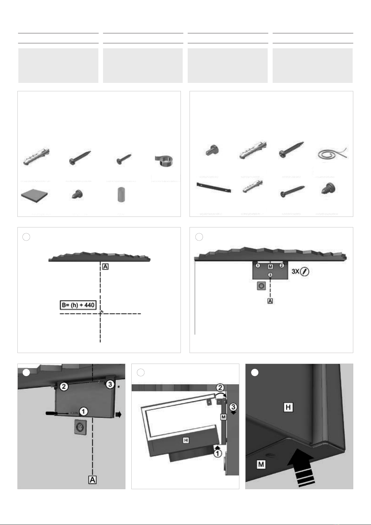
NL - Montage materialen recirculatiekit
FR - Kit de recirculation des matériaux de montage
DU - Montagematerial Umluft Kit
EN - Installation materials recirculation kit
NL
Belangrijk: lees voor-
afgaand de voorschriften
voor veiligheid en montage.
DU
Wichtig: Bitte lesen
Sie die Sicherheits- und
Installationshinweise, bevor
Sie beginnen.
FR
Important: Veuillez lire
les instructions de sécurité
et d’installation avant de
commencer.
EN
Important: Please read
the safety and installation
instructions before you start.
1
3
2
4 5
NL - Montage materialen afzuigkap
FR - Matériel de montage de la hotte aspirante
DU - Materialien zur Montage der Dunstabzugshaube
EN - Cooker hood installation materials
3x 906-055
1x 7600060
3x 906-143
4x 906-151
3x 906-192
1x 906-217
1x 906-292
2x 906-035
2x 7600-024
2x 906-055
6x 906-115
2x 906-143
6x 906-197
1x 801-006
4x 906-151
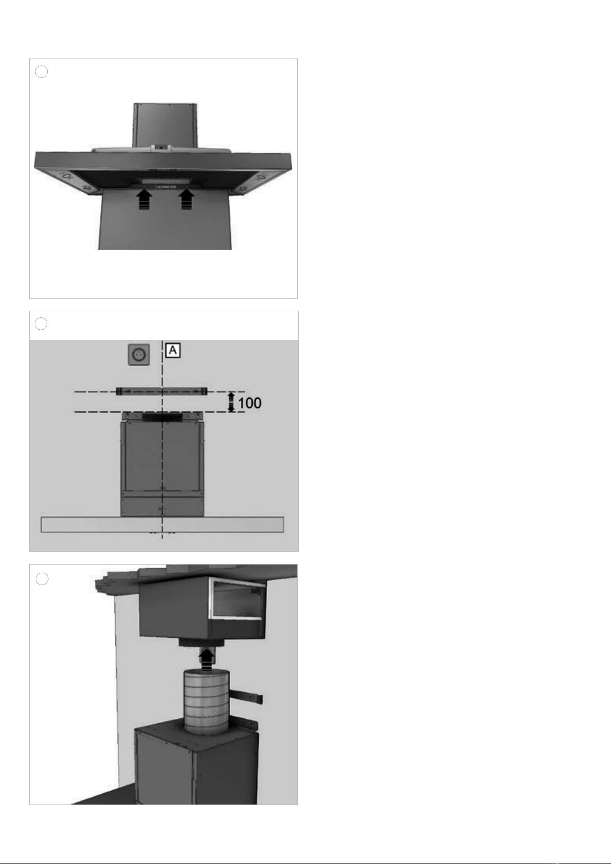
NL 4 INSTALLATIE
1
Voorbereiding montage: Teken op de muur de verticale
aslijn A van de schouwkap. De advieshoogte “h” tussen
de onderkant van de schouwkap en de kookplaat is
voor
• Advies montagehoogte met elektrische of keramische
kookplaat (Hmin-Hmax) (mm): 600 - 750
• Montagehoogte met gas of inductie kookplaat
(Hmin-Hmax) (mm): 650-750
De waterpaslijn B wordt getekend op de gekozen
hoogte van “h” + 440 mm.
Plaats het stopcontact dichtbij de verticale aslijn A
binnen de breedte van de schouwen en boven het
motorhuis en onder de recirculatiebox (M).
2 3
Positioneer de montageplaat (M) van de recirculatiebox
in het midden van de verticale aslijn en tegen het
plafond. In geval van een stenen muur markeer en boor
de 3 gaten (Ø8mm). Gebruik de pluggen (3x 906.055)
en schroeven (3x 906.143) om de montageplaat (M) te
installeren. In geval van een houten bevestigingsmuur
de spaanplaatschroeven (3x 906.192) gebruiken.
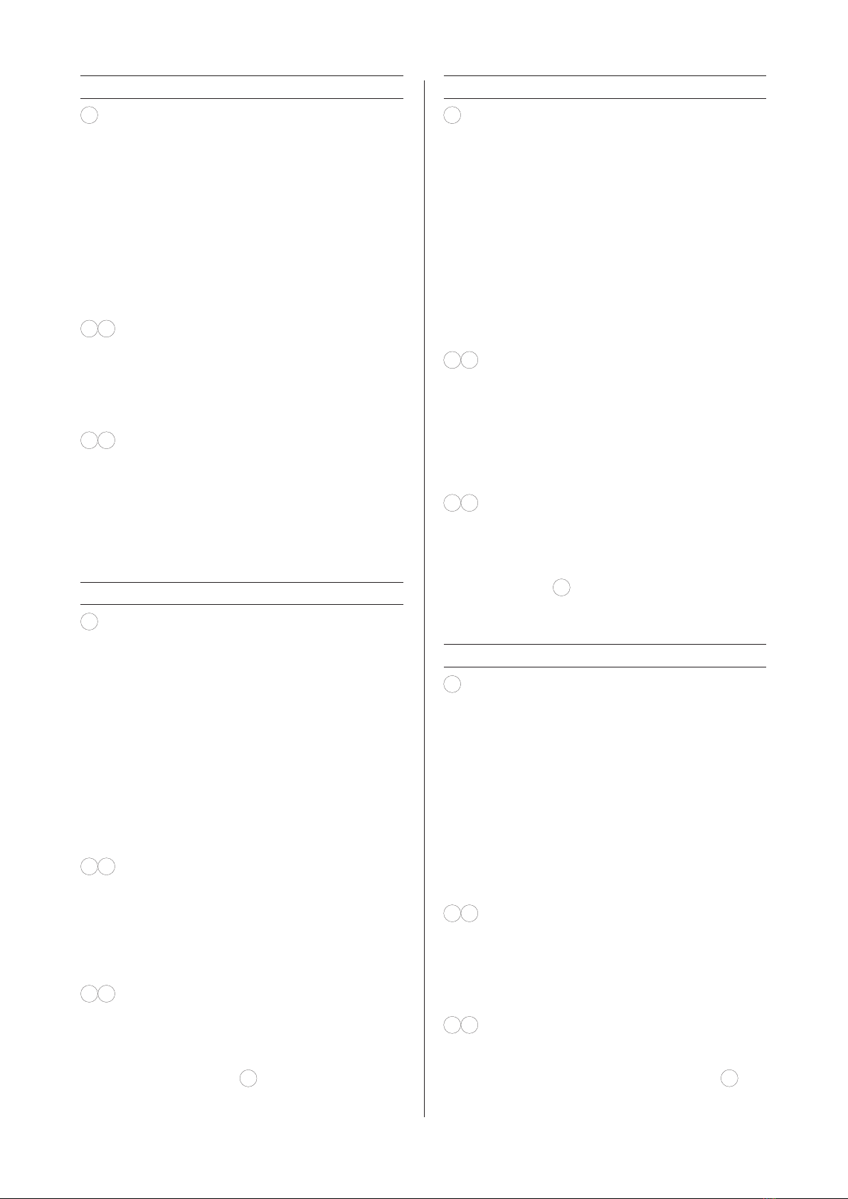
4 5
Positioneer de recirculatiebox (H) op de montageplaat
(M). Let op bij het plaatsen van de recirculatiebox dat
deze niet vervormd of opengevouwen wordt tijdens
montage.
1.
Laat H steunen op de uitstekende lip van M.
2. Kantel H naar het muurbeugel M toe.
3. Haak de lip van H achter de muurbeugel M.
DE 4 INSTALLATION
1
Vorbereitung der Montage: Zeichnen Sie auf der
Wand die vertikale Achsenlinie A der Wandhaube an.
Die empfohlene Höhe „h“ zwischen Unterseite der
Wandhaube und der Kochfläche beträgt für
• Die empfohlene Montagehöhe bei einem Elektrrooder
Keramikkochfeld beträgt mindestens 600 mm und
höchstens 750 mm.
• Die empfohlene Montagehöhe bei einem Gasoder
Induktionskochfeld beträgt mindestens 650 mm und
höchstens 750 mm.
Die horizontale Linie B wird auf der gewählten Höhe
von „h“ + 440 mm gezeichnet.
Positionieren Sie die Steckdose nahe der vertikalen
Achsenlinie A innerhalb der Breite der Schächte und
über dem Motorgehäuse und unter der Umluftbox (M).
2 3
Halten Sie die Montageplatte (M) der Umluftbox gegen
die Decke und positionieren Sie sie in der Mitte der
vertikalen Achsenlinie. Im Fall einer Steinwand zeichnen
Sie die 3 Löcher an und bohren Sie sie (Ø 8 mm).
Stecken Sie die Dübel (3x 906-055) und die Schrauben
(3x 906-143) in die Löcher, um die Montageplatte (M)
zu installieren. Im Fall einer Befestigungswand aus
Holz verwenden Sie die Spanplattenschrauben (3x
906-192).
4 5
Positionieren Sie die Umluftbox (H) auf der Montageplatte
(M). Achten Sie beim Positionieren der Umluftbox
darauf, dass sie während der Montage nicht verformt
oder geknickt wird.
1. Setzen Sie H auf die hervorstehende Kante von M
auf (siehe
5
).
2. Kippen Sie H zum Wandbügel M hin.
3.
Haken Sie die Kante von H hinter den Wandbügel M.
FR 4 INSTALLATION
1
Préparation du montage : Tracez sur le mur l’axe
vertical A de la hotte à cheminée. La hauteur « h »
conseillée entre le bas de la hotte à cheminée et la
table de cuisson est
• La hauteur de montage recommandée avec une
table de cuisson électrique ou céramique est de
600 mm minimum et 750 mm maximum.
• La hauteur de montage avec une table de cuisson
au gaz ou à induction est de 650 mm minimum et
750 mm maximum.
La ligne horizontale B sera tracée à la hauteur
« h » choisie + 440 mm.
Placez la prise de courant près de l’axe vertical A
l’intérieur de la largeur des gaines, au-dessus du
boîtier du moteur et sous la boîte de recirculation (M).
2 3
Positionnez la plaque de montage (M) de la boîte
de recirculation au milieu de l’axe vertical et contre
le plafond. Dans le cas d’un mur en pierre, marquez
et percez 3 trous (Ø 8mm). Utiliser les chevilles (3x
906-055) et les vis (3x 906-143) pour installer la plaque
de montage (M). Dans le cas d’un mur de fixation en
bois, utilisez des vis pour panneaux en aggloméré (3x
906-192).
4 5
Positionnez la boîte de recirculation (H) sur la plaque
de montage (M). Lors de la mise en place de la boîte
de recirculation, assurez-vous qu’elle ne se déforme
pas ou ne se déplie pas pendant le montage.
1. Faites en sorte que H soit soutenue par la patte
saillante de M (voir
5
).
2. Basculez H vers l’étrier mural M.
3. Accrochez la patte de H derrière l’étrier mural M.
EN 4 INSTALLATION
1
Preparations for mounting: Draw the vertical axis A
of the chimney hood on the wall. The recommended
height ‘h’ between the bottom of the chimney hood
and the cooking plate is for
• The recommended mounting height for an electrical
or ceramic cooking plate is min. 600 mm and max.
750 mm.
• The mounting height for a gas or induction cooking
plate is min. 650 mm and max. 750 mm.
The level line B is drawn at the chosen height of
‘h’ + 440 mm.
Position the socket outlet near the vertical axis A within
the width of the shafts and above the motor housing
and below the recirculation box (M).
2 3
Position the mounting plate (M) of the recirculation
box in the middle of the vertical axis and against the
ceiling. In case of a stone wall, mark and drill the 3
holes (Ø 8 mm). Install the mounting plate (M) using
the plugs (3x 906-055) and screws (3x 906-143). In
case of a wooden mounting wall, use the chipboard
screws (3 x 906-192).
4 5
Position the recirculation box (H) on the mounting plate
(M). Make sure when positioning the recirculation box
that it is not deformed or unfolded when mounting.
1. Let H rest on the protruding lip of M (see
5
).
2. Tilt H towards the wall bracket M.
3. Hook the lip of H behind the wall bracket M.
7

8
7
9
10 11
8
6

NL
6 7
Schroef de recirculatiebox H vast aan montageplaat
M (4x 906-151).
Zorg dat de bevestigingslip van H zich altijd
aan de buitenzijde bevindt!
Na het monteren van de recirculatiebox kan de
wandschouw gemonteerd worden. Gebruik voor
het monteren van de dampkap en de schouwen
de montagematerialen die bij de schouwkap zijn
geleverd.
8De boormal bevindt zich in de montage instructie
van de wandschouw. Plaats deze boormal op het
kruispunt van de aslijn A en de waterpaslijn B en
teken de 2 gaten af op de waterpaslijn. Boor met
een 8mm boor de gaten in de muur.
9
Gebruik de grote pluggen (906055) en draai de
bijbehorende grote schroeven (906143) gedeeltelijk
in de muur. Let op, de schroeven nog niet helemaal
indraaien!
Hang de wandschouwkap met de beugel bovenop
het motorhuis over deze schroeven.
10 11
Positioneer de schouwkap C waterpas door de
schroeven op de schouwkap zodanig te draaien
zodat de schouwkap waterpas komt te hangen. Ook
de hoogte van de schouwkap kan nog iets gesteld
worden door de schroeven in en uit te draaien.
Let op, de schroeven in de muur nog niet vast
draaien!
DE
6 7
Schrauben Sie die Umluftbox H an der Montageplatte
M (4x 906-151) fest.
Sorgen Sie dafür, dass sich die Befesti-
gungskante von H immer auf der Außenseite
befindet!
Nach der Montage der Umluftbox kann die Wandhaube
montiert werden. Verwenden Sie für die Montage der
Dunstabzugshaube und der Schächte das mit der
Dunstabzugshaube mitgelieferte Montagematerial.
8Die Bohrschablone befindet sich in der Montage-
anleitung für die Dunstabzugshaube. Halten Sie die
Bohrschablone auf den Schnittpunkt der Achsenlinie
A und der horizontalen Linie B und zeichnen Sie
die beiden Löcher auf der horizontalen Linie an.
Bohren Sie die Löcher mit einem 8-mm-Bohrer in
die Wand.
9
Verwenden Sie die großen Dübel (906055) und
drehen Sie die zugehörigen großen Schrauben
(906143) teilweise in die Wand. Achten Sie darauf,
die Schrauben noch nicht vollständig festzudrehen!
Hängen Sie Wandhaube mit dem Bügel oben auf
dem Motorgehäuse über diese Schrauben.
10 11
Positionieren Sie die Wandhaube C horizontal,
indem Sie die Schrauben an der Wandhaube so
verdrehen, dass die Wandhaube horizontal hängt.
Auch die Höhe der Wandhaube kann etwas korrigiert
werden, indem man die Schrauben hinein- oder
herausdreht.
Achten Sie darauf, die Schrauben in der Mau-
er noch nicht festzudrehen.
FR
6 7 Vissez la boîte de recirculation H contre la plaque
de montage M (4x 906-151).
Assurez-vous que la patte de fixation de H se
trouve toujours du côté extérieur !
Après avoir monté la boîte de recirculation, vous
pouvez monter la cheminée murale. Pour le montage
de la hotte et des gaines, utilisez le matériel de
montage fourni avec la hotte à cheminée.
8Le gabarit de perçage se trouve dans la notice de
montage de la cheminée murale. Placez ce gabarit
de perçage à l’intersection de l’axe A et de la ligne
horizontale B et marquez les 2 trous sur la ligne
horizontale. Percez les trous dans le mur à l’aide
d’une mèche de 8 mm.
9
Utilisez les grandes chevilles (906055) et vissez les
grandes vis correspondantes (906143) partiellement
dans le mur. Attention ! Ne serrez pas les vis à fond!
Accrocher la hotte à cheminée murale avec l’étrier
en dessus du boîtier du moteur par-dessus ces vis.
10 11
Mettez la hotte à cheminée C en position horizontale
en tournant les vis sur la hotte de manière ce que la
hotte à cheminée se trouve accrochée en position
parfaitement horizontale. De même, vous pouvez
ajuster encore légèrement la hauteur de la hotte à
cheminée en serrant et en desserrant les vis.
Ne serrez pas encore les vis à fond dans le
mur !
EN
6 7
Screw the recirculation box H onto the mounting
plate M (4x 906-151).
Make sure that the attachment lip of H is
always on the outside!
After having mounted the recirculation box, the
wall-mounted chimney hood can be mounted. Use
the mounted materials supplied with the chimney
hood for mounting the hood and the shafts.
8
The drilling jig is to be found in the mounting
instructions of the wall-mounted hood. Place this
drilling jig on the crossing point of the axis A and
the level line B and draw the 2 holes on the level
line. Drill holes in the wall using an 8 mm drill.
9Use the large plugs (906055) and partly screw the
accompanying large screws (906143) into the wall.
Attention: do not fully screw in the screws yet!
Hang the wall-mounted chimney hood with the
bracket on top of the motor housing over these
screws.
10 11
Level the chimney hood C by turning the screws
on the chimney hood such, that the chimney hood
is hanging level. The height of the chimney hood
can slightly be adjusted by screwing the screws in
and out.
Do not tighten the screws in the wall yet!
9
10
12
14
13
NL
12
Open de onderplaat en neem het vetfilter uit de
schouwkap. In de achterzijde van de schouwkap
bevinden zich 2 gaten. Markeer deze gaten op de
muur. Sluit de onderplaat en neem de wandschouwkap
weer van de muur, om de gemarkeerde gaten op de
muur te boren. Boor de gaten met een 6mm boor
en gebruik de kleine pluggen (906115). Positioneer
de schouwkap opnieuw tegen de muur. Controleer
of alles nog waterpas hangt. Gebruik de kleine
schroeven (906197) om de wandschouwkap goed
tegen de muur te bevestigen. Draai nu ook de
schroeven boven in de muur goed vast.
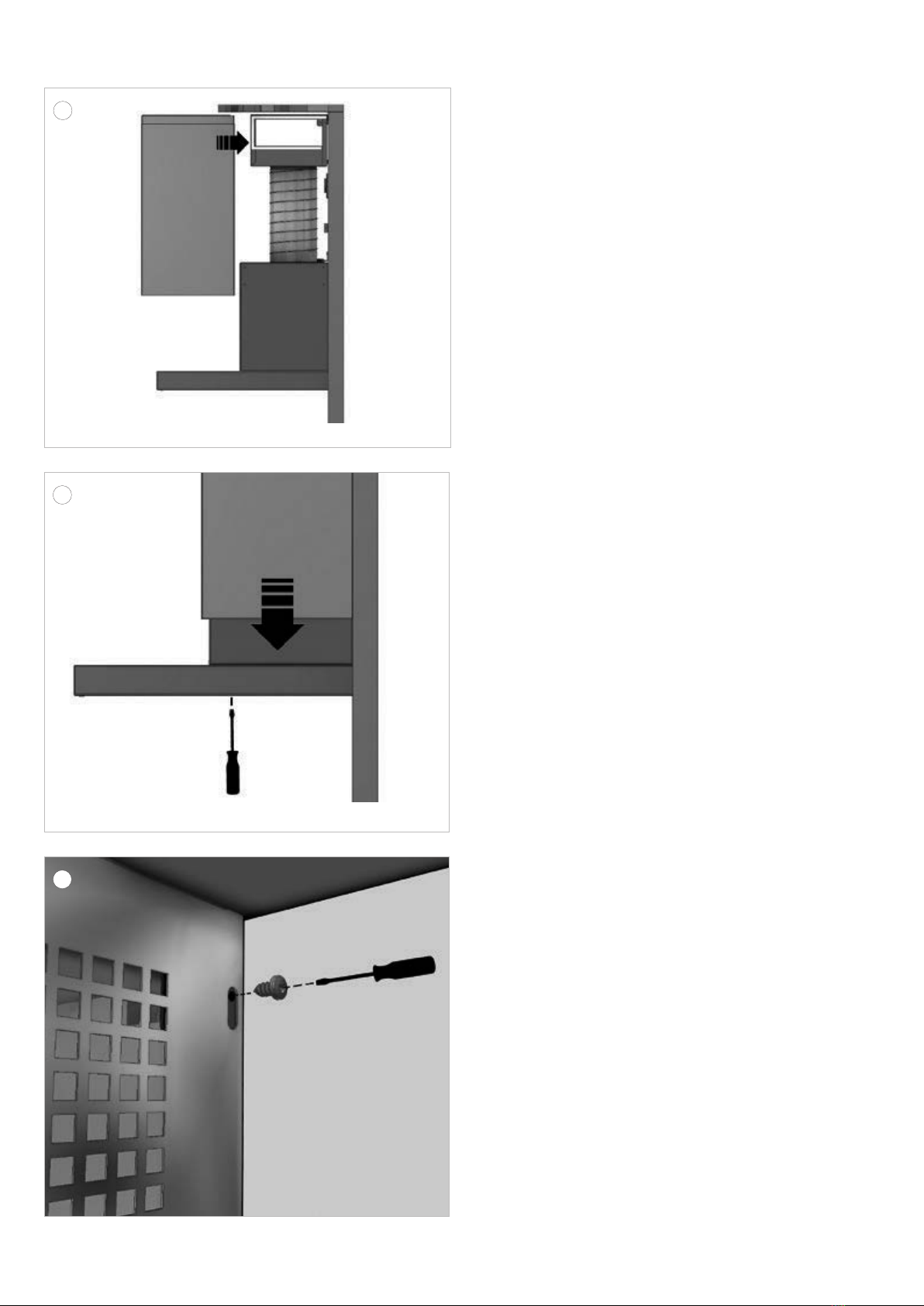
13
Installeer op de verticale aslijn de onderste
afstandsbeugel, 100mm gemeten vanaf de bovenzijde
van de montagebeugel tot het hart van het boorgat.
Gebruik de pluggen (906115) en de schroeven
(906197). Monteer de afstandsbeugel zodanig dat
deze loodrecht en in het midden van de verticale
aslijn op de muur komt.
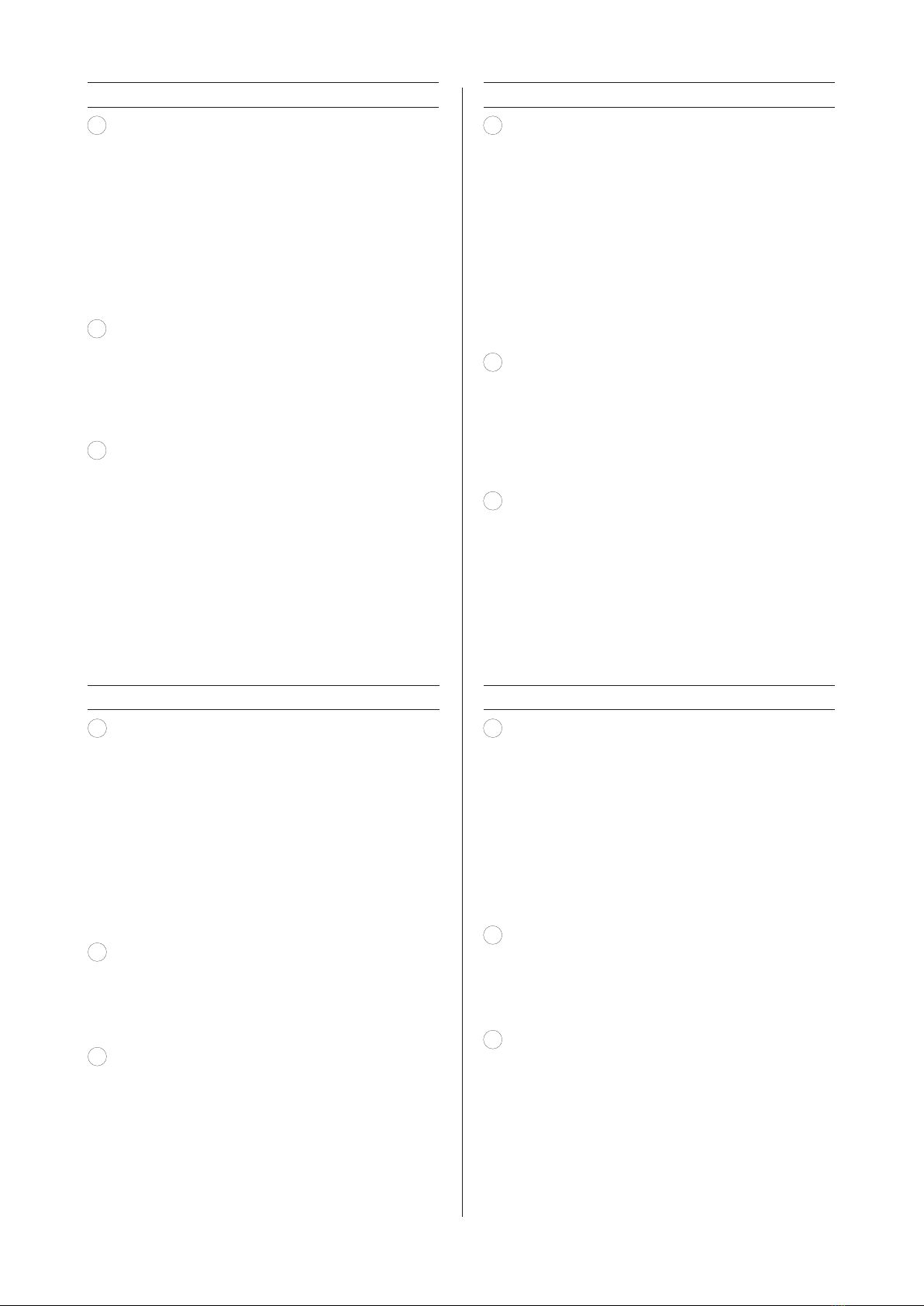
14
Plaats de meegeleverde afvoerbuis (906-217) op
de aansluittuit met behulp van de meegeleverde
aluminiumtape (906-292) of met een slangklem
(niet meegeleverd). Rek de afvoerbuis uit tot tegen
de inlaat van de koolstoffilterbox en zet vast met
aluminium tape of een slangklem. Plaats vervolgens
de stekker in het stopcontact.
DE
12
Öffnen Sie die Unterseite und nehmen Sie den Fettfilter
aus der Wandhaube heraus. In der Rückseite der
Handhaube befinden sich 2 Löcher. Zeichnen Sie
diese Löcher auf der Wand an. Schließen Sie die
Unterseite und nehmen Sie die Wandhaube wieder
von der Wand ab, um die angezeichneten Löcher
in die Wand zu bohren. Bohren Sie die Löcher mit
einem 6-mm-Bohrer und verwenden Sie die kleinen
Dübel (906115). Positionieren Sie die Wandhaube
wieder an der Wand. Kontrollieren Sie, ob alles
horizontal ausgerichtet ist. Benutzen Sie die kleinen
Schrauben (906197), um die Wandhaube sicher an
der Wand zu befestigen. Drehen Sie jetzt auch die
Schrauben in der Wand fest.
13 Installieren Sie auf der vertikalen Achsenlinie den
unteren Abstandsbügel so, dass der Abstand von
der Oberseite des Montagebügels zur Mitte des
Bohrlochs 100 mm beträgt. Benutzen Sie die Dübel
(906115) und die Schrauben (906197). Montieren
Sie den Abstandsbügel so, dass er senkrecht und
in der Mitte der vertikalen Achsenlinie auf der Wand
sitzt.
14
Setzen Sie das mitgelieferte Abluftrohr (906-217)
unter Verwendung des mitgelieferten Aluminium-
Klebebands (906-292) oder mit einer Schlauchklemme
(nicht mitgeliefert) auf die Anschlusstülle auf.
Ziehen Sie das Abluftrohr bis zum Einlass der
Kohlenstofffilterbox heraus und fixieren Sie es mit
Aluminium-Klebeband oder einer Schlauchklemme.
Stecken Sie anschließend den Stecker in die
Steckdose.
FR
12
Ouvrez la plaque de fond et retirez le filtre à graisse
de la hotte à cheminée. L’arrière de la hotte à
cheminée comporte 2 trous. Marquez ces trous sur
le mur. Fermez la plaque de fond et retirez la hotte
du mur pour percer les trous marqués sur le mur.
Percez les trous à l’aide d’une mèche de 6 mm et
utilisez les petites chevilles (906115). Positionnez la
hotte à cheminée à nouveau contre le mur. Vérifiez
si l’ensemble est encore accroché de manière
parfaitement horizontale. Utilisez les petites vis
(906197) pour bien fixer la hotte à cheminée murale
contre le mur. Maintenant, serrez bien les vis du
dessus dans le mur.
13
Installez l’étrier d’écartement inférieur sur l’axe
vertical à 100 mm mesurés entre le haut de l’étrier
de montage et l’axe du trou percé. Utilisez les
chevilles (906115) et les vis (906197). Montez l’étrier
d’écartement de manière à ce qu’il se retrouve
d’aplomb et au milieu de l’axe vertical sur le mur.
14
Placez le tuyau d’évacuation fourni (906-217) sur le
raccord à l’aide du ruban adhésif aluminium fourni
(906-292) ou d’un collier de serrage (non inclus).
Étirez le tuyau d’évacuation jusque contre l’entrée
de la boîte du filtre à charbon puis fixez-le à l’aide
du ruban adhésif aluminium ou d’un collier de
serrage. Puis placez insérez la fiche dans la prise
de courant.
EN
12
Open the bottom plate and remove the grease filter
from the chimney hood. There are 2 holes on the
rear side of the chimney hood. Mark these holes
on the wall. Close the bottom plate and take the
chimney hood off the wall in order to be able to drill
the marked holes. Drill the holes with a 6 mm drill and
use the small plugs (906115). Position the chimney
hood against the wall again. Check if the hood is
still hanging level. Use the small screws (906197)
to properly attach the wall-mounted chimney hood
to the wall. Now also tighten the screws above in
the wall.
13
Install the lower spacer bracket on the vertical
axis 100 mm from the upper side of the mounting
bracket to the centre of the drilled hole. Use the
plugs (906115) and the screws (906197). Mount the
spacer bracket such, that it is perpendicular to and
in the centre of the vertical axis on the wall.
14
Place the supplied exhaust pipe (906-217) onto the
connection nozzle using the supplied aluminium
tape (906-292) or using a hose clamp (not included).
Extend the exhaust pipe until against the inlet of
the carbon filter box and fix it with aluminium tape
or a hose clamp. Then put the plug into the socket
outlet.
11
12
16
17
15
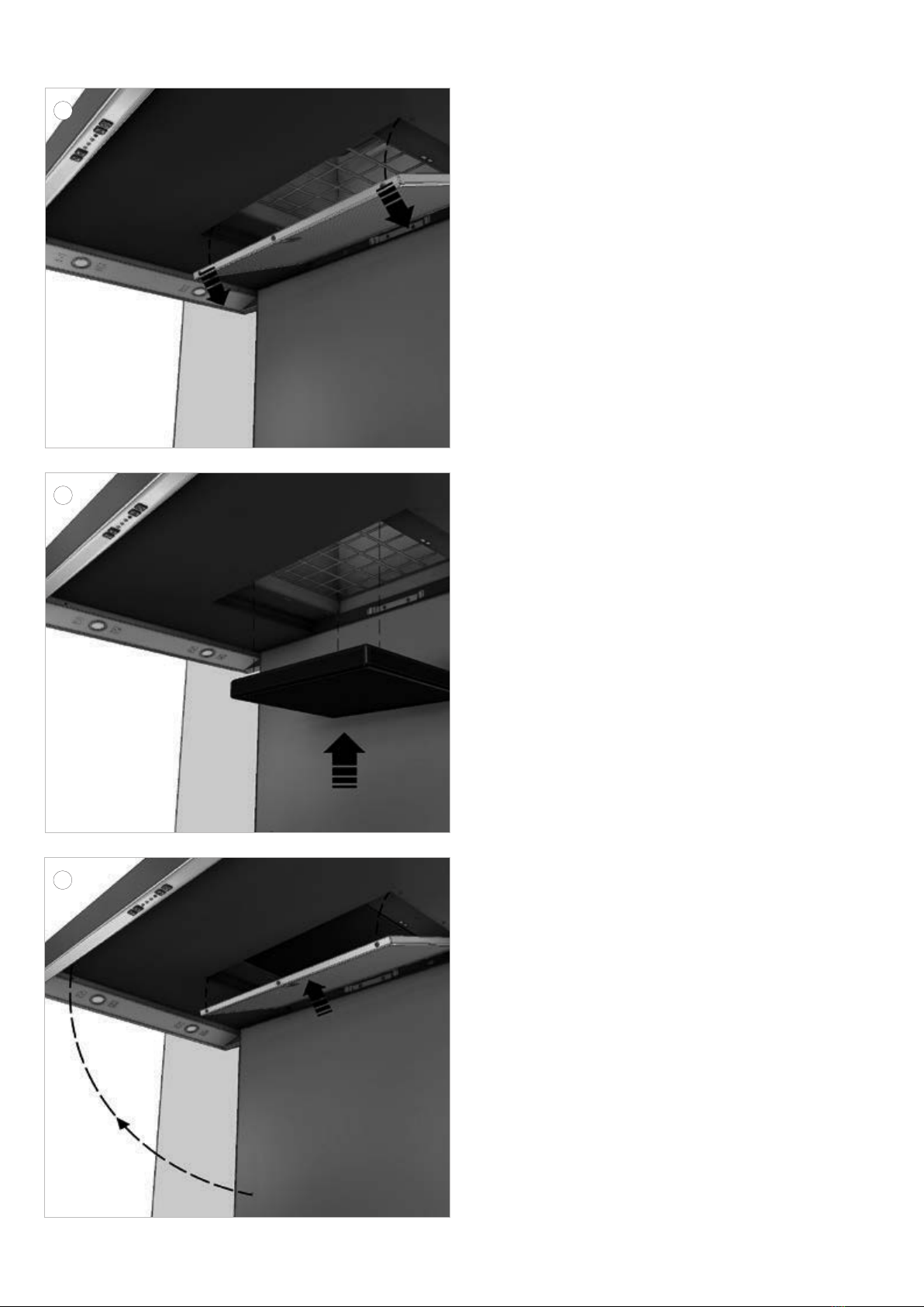
NL
15
Neem de schouwen set uit de verpakking van
de dampkap. Schuif de bovenste schouw uit de
onderste en draai de schouw om, zodat het rooster
bovenaan komt. Schuif de bovenste schouw terug
in de onderste schouw.
Breng de schouwen voorbij de recirculatiebox tot
tegen het plafond en duw deze vervolgens achter
de recirculatiebox!
16
Laat de buitenste schouw zakken tot op de schouwkap.
Klem de buitenste schouw vast aan de onderste
afstandhouder. Open de onderplaat en neem het
filter uit de schouwkap. Schroef met de 4 schroeven
(906151) de schouw vast, vanuit de binnenkant van
de schouwkap.
17
Duw de bovenste schouw achter de koolstoffilterbox.
Schroef deze daarna vast met de bijhorende inox
schroeven (2x 906-035).
DE
15 Nehmen Sie das Schachtset aus der Verpackung
der Dunstabzugshaube. Schieben Sie den oberen
Schacht aus dem unteren heraus und drehen Sie
den Schacht um, so dass sich das Gitter oben
befindet. Schieben Sie den oberen Schacht zurück
in den unteren Schacht.
Führen Sie die Schächte an der Umluftbox vorbei
bis an die Decke und schieben Sie sie anschließend
hinter die Umluftbox!
16
Senken Sie den äußeren Kamin bis auf die
Dunstabzugshaube ab. Klemmen Sie den äußeren
Schacht am unteren Abstandshalter fest. Öffnen Sie
die Unterseite und nehmen Sie den Filter aus der
Wandhaube heraus. Schrauben Sie den Schacht
mit den 4 Schrauben (906151) vom Inneren der
Dunstabzugshaube aus fest.
17
Schieben Sie den oberen Schacht hinter die
Kohlenstofffilterbox. Schrauben Sie ihn anschließend
mit den zugehörigen Edelstahlschrauben fest (2x
906-035).
FR
15
Retirez la paire de gaines de l’emballage de la hotte.
Dégagez la gaine supérieure de la gaine inférieure
et retournez la gaine de manière à ce que la grille
se trouve en haut. Réinsérez la gaine supérieure
dans la gaine inférieure.
Amenez les gaines devant la boîte de recirculation
jusque contre le plafond puis poussez-les derrière
la boîte de recirculation !
16
Abaissez la cheminée extérieure jusque sur la
hotte à cheminée. Fixez la gaine extérieure contre
l’entretoise inférieure. Ouvrez la plaque de fond et
retirez le filtre de la hotte à cheminée. À l’aide des
4 vis (906151), serrez la gaine depuis l’intérieur de
la hotte à cheminée.
17
Poussez la gaine supérieure derrière la boîte du
filtre à charbon. Puis vissez-la à l’aide des vis en
acier inoxydable (2x 906-035).
EN
15
Remove the shaft set from the packaging of the
hood. Slide the upper shaft out of the lower shaft
and turn it around, so the grate is at the top. Slide
the upper shaft back into the lower shaft.
Move the shafts beyond the recirculation box
unto the ceiling and then push them behind the
recirculation box!
16
Lower the outer shaft unto the chimney hood.
Clamp the outer shaft onto the lower spacer. Open
the bottom plate and remove the filter from the
chimney hood. Tighten the shaft from the inside
of the chimney hood with the 4 screws (906151).
17 Push the upper shaft behind the carbon filter box.
Then tighten them using the corresponding stainless
steel screws (2 x 906-035).
13
14
18
19
20

NL
Plaatsen van de Monoblock recirculatiefilter
18
Open de onderplaat en neem het aluminium vetfilter
van de schouwkap.
19 Plaats de Monoblock recirculatiefilter (7600060) in
de voorziene opening.
20 Plaats de vetfilter in de afzuigkap.
Kleef de sticker, met hierop vermeld de levensduur
an deze Monoblock reciculatiefilter, naast de opening
van het vetfilter.
Sluit de onderplaat.
Bij de keuze voor recirculatie dient altijd het
recirculatieprogramma op de afzuigkap inge-
steld te worden. Lees hiervoor de aanwijzin-
gen in de gebruiksaanwijzing van uw toestel.
DE
Positionieren des Monoblock-Umluftfilters
18
Öffnen Sie die Unterseite und nehmen Sie den
Fettfilter aus Aluminium aus der Wandhaube heraus.
19
Positionieren Sie den Monoblock-Umluftfilter (7600060)
in der vorgesehenen Öffnung.
20
Setzen Sie den Fettfilter zurück in die Dunstabzugs-
haube.
Kleben Sie den Aufkleber, der die Lebensdauer
dieses Monoblockfilters anzeigt, neben die Öffnung
des Fettfilters.
Schließenund Sie der Unterplatte wieder.
Wenn Sie Umluft wählen, stellen Sie das
Umluftprogramm immer an der Dunstabzugs-
haube ein. Lesen Sie dazu die Hinweise in der
Bedienungsanleitung Ihres Gerätes.
FR
Mise en place du filtre de recyclage Monoblock
18
Ouvrez la plaque de fond et retirez le filtre à graisse
en aluminium de la hotte à cheminée.
19 Placez le filtre de recyclage Monoblock (7600060)
dans l’ouverture prévue.
20 Remettez le filtre à graisse dans la hotte.
Collez l’autocollant indiquant la durée de vie de ce
filtre de monobloc à côté de l’ouverture du filtre à
graisse.
Fermez le carter.
Lorsque vous sélectionnez la recirculation,
réglez toujours le programme de recircu-
lation sur la hotte aspirante. Pour ce faire,
lisez les instructions figurant dans le mode
d’emploi de votre appareil.
EN
Install the Monoblock recirculation filter
18 Open the bottom plate and remove the aluminium
grease filter from the chimney hood.
19 Place the Monoblock recirculation filter (7600060)
in the opening provided.
20 Put the grease filter back in the cooker hood.
Stick the sticker indicating the service life of this
monoblock filter next to the opening of the grease
filter.
Close the lower plate.
When selecting recirculation, always set the
recirculation program on the extractor hood.
To do so, read the instructions in the opera-
ting instructions of your appliance.
15

NOVY nv behoudt zich het recht voor te allen tijde en zonder voorbehoud de constructie en de prijzen van haar producten te wijzigen.
NOVYSA se réserve le droit de modifier à tout moment et sans réserve la fabrication et les prix de ses produits.
Die NOVY AG behält sich das Recht vor, zu jeder Zeit und ohne Vorbehalt die Konstruktion und die Preise ihrer Produkte zu ändern.
NOVY nv reserves the right at any time and without reservation to change the structure and the prices of its products.
NOVY nv
Noordlaan 6
B - 8520 KUURNE
Tel. 056/36.51.00
Fax 056/35.32.51
E-mail: novy@novy.be
http://www.novy.be
France: Tél: 0320.940662
Deutschland und Österreich: Tel: +49 (0)511.54.20.771
Nederland: Tel.: +31 (0)88-0119110
United Kingdom: +44 (0)207 866 2493
España: Tel.: +34 938 700 895
Italia: Tel.: +39 039.20.57.501
Other manuals for 7600.400
1
This manual suits for next models
4
Table of contents
Other Novy Ventilation Hood manuals

Novy
Novy Zen 7510 User manual

Novy
Novy 810/16 User manual

Novy
Novy Fusion Pro 87 Series User manual

Novy
Novy 1801 User manual

Novy
Novy 7530 User manual

Novy
Novy 7550 User manual

Novy
Novy Pure'line Cubic 6833 User manual

Novy
Novy 7550 User manual

Novy
Novy 6835/15 User manual

Novy
Novy Mini Pureline 800993 User manual

Novy
Novy 230 CLOUD User manual

Novy
Novy 7600.400 User manual

Novy
Novy Panorama 120 Pro 4 zones User manual

Novy
Novy Easy 1861 User manual

Novy
Novy 7811/2 User manual

Novy
Novy 6201/15 User manual

Novy
Novy 230 CLOUD User manual

Novy
Novy Up 40 00 Series User manual

Novy
Novy 7510/16 User manual

Novy
Novy 230 CLOUD User manual


