NRS ELC-24/30-M-D Service manual

www.nationalrailwaysupply.com
1-800-357-3572 1 38542D
NATIONAL
RAILWAY
SUPPLY
Installing, Operating and
Service Instructions for the
ELC-24/30-M-D Solid State Charger
MODEL ELC-24/30-M-D
BATTERY CHARGER
PLEASE SAVE THESE IMPORTANT SAFETY AND OPERATING INSTRUCTIONS
For correct operation of the equipment, it is important to read and be familiar
with this entire manual before installing and operating the charger.
DO NOT DISCARD THIS MANUAL AFTER READING.
LOOK FOR THIS SYMBOL TO POINT OUT SAFETY PRECAUTIONS. IT MEANS:
BECOME ALERT—YOUR SAFETY IS INVOLVED. IF YOU DO NOT FOLLOW THESE
SAFETY INSTRUCTIONS, INJURY OR PROPERTY DAMAGE CAN OCCUR.
1. IMPORTANT SAFETY INSTRUCTIONS
a. Before using the battery charger, read all the
instructions and caution markings on the
battery charger, the battery, and all of the
products using the battery.
b. Do not touch the uninsulated parts of the AC
input or the DC wires, the charger's binding
posts, or the battery terminals as there is a
possibility of electrical shock.
c. Batteries produce hydrogen gas while
operating, which can explode if ignited.
Never smoke, use an open flame, or create
sparks in the vicinity of the battery. Ventilate
the area well when the battery is charging in
an enclosed area.
d. Batteries contain caustic material which may
cause burns. Do not get in eyes, on skin, or
clothing. If the gelled or liquid content of the
batteries contacts the skin or clothing, wash
the area thoroughly with water. In the case
of contact with the eyes, flush immediately
with clean water for 15 minutes and obtain
medical attention.
e. Connect or disconnect the battery plug only
when the charger output is off to prevent
arcing or burning.
f. Only qualified personnel should program or
service this equipment.
g. De-energize all AC and DC power
connections before servicing this unit. If
injury does occur, apply standard treatment
for electrical shock and, if necessary, consult
with a physician.
h. The charger is not for outdoor use. Do not
expose the charger to rain or snow.
i. Do not operate the charger if it has received
a sharp blow, been dropped, or otherwise
damaged. Take it to a qualified service
center.
j. Do not disassemble the charger. Have the
charger examined by a NATIONAL
RAILWAY SUPPLY service agent. If the
charger is assembled incorrectly, damage to
the charger and the batteries or an electrical
shock may result.
2. DESCRIPTION
The NATIONAL RAILWAY SUPPLY (NRS) charger
model ELC-24/30-M-D is a convection-cooled, solid
state, SCR regulated charger that provides either a
constant current or constant voltage output. The
charger can be set to charge batteries within a
voltage range of 20.0 to 35.0 volts for gel-cell, liquid
lead-acid, nickel cadmium, nickel iron, and starved
electrolytic batteries.

www.nationalrailwaysupply.com
1-800-357-3572 2 38542D
3. THEORY OF OPERATION
When the charger is connected to the desired AC
voltage source (115 or 230), the transformer creates
auxiliary voltages for the electronic control module.
The electronic control module controls and monitors
the charger so it will perform properly. The
transformer also supplies the power output used for
charging the batteries and provides electrical
isolation between the charger's output and the AC
source.
The charger's output current flows through a shunt
and is sensed by the electronic control module along
with the charger's output voltage. These values are
converted into drive pulses for the SCRs by the
control module. This pulsating charge current (a
pulse occurs each time an SCR is on) is then filtered
by a large capacitor and the batteries to provide a
smooth output.
The charger is an "IE" profile which is: (a) High rate
constant current, and (b) Constant voltage. When
the charger is first started, the SCRs will conduct for
a certain portion of the sinusoidal anode voltage to
provide the required charging current at the low level
of battery voltage. In this start region, a constant 30-
amp current is applied to the battery. The SCR
conduction will then increase as the battery voltage
increases in order to provide a higher output voltage
while maintaining a constant charging current.
When the battery voltage reaches the float voltage
(the voltage set with the switches), the SCRs will
start to decrease their output. This causes the
charger to automatically change from a constant
current charge region to a constant voltage charge
region. As the batteries become fully charged, the
output current decreases. A continuous constant
float voltage will be supplied to the batteries to
maintain their charge.
Another feature of the charger is temperature
compensation, which keeps the batteries from
getting under- or over-charged. TEMPERATURE
COMPENSATION ONLY OCCURS WHEN USING
A TEMPERATURE PROBE. The red LED on the
front of the charger will be off when using a
functional temperature probe. If the LED is on,
either a temperature probe is not being used, or the
temperature probe is working improperly.
Temperature compensation uses a temperature
reference of 77F (25C), a voltage reference of 2.23
volts (the voltage of a standard gel-cell battery at
77F), and a compensation value of 3.0 mV per F,
or 5.4 mV per °C. The equivalent equation for the
compensated voltage is:
Vcomp = V –k (t - 77F)
Where V is the voltage of the battery at 77F, t is
the temperature in F, and k = V (.003 / 2.23).
The control module has a temperature
compensation range between 32°F and 95°F (0°C
and 35°C) that does not allow charger voltage to
increase or decrease beyond the calculated values.
Example 1:
If a 26.8 volt battery is charging and the
temperature increases to 95F, then the output
voltage decreases to 26.1 volts.
26.8 - .036 (95F - 77F) = 26.1
Example 2:
If a 29.00 volt battery is charging and the
temperature increases to 95F, then the output
voltage decreases to 28.3 volts.
29.00 - .039 (95F - 77F) = 28.3
Example 3:
If 35.0 volt batteries are charging and the
temperature decreases to 32F, the output voltage
increases to 37.1 volts.
35.0 –.047 (32F - 77F) = 37.1
4. RECEIVING AND INSTALLING THE
CHARGER
Proper installation of the charger is important in
order to achieve good charger performance and to
prevent damage to the charger and batteries. When
a charger is received, a check for possible in-transit
damage should be made. If any damage is found, it
should be reported as a claim to the carrier. To
permit free air flow for convention cooling, allow two
inches (2") minimum between the charger sides and
other equipment and four inches (4") minimum on
top of the charger.
WARNING: NEVER PLACE ANYTHING ON
TOP OF THE CHARGER WHILE OPERATING.
DAMAGE TO THE CHARGER OR BATTERIES
COULD OCCUR.
WARNING: THE CHARGER MUST BE SET
UP FOR THE PROPER USER SPECIFICATIONS
BEFORE STARTING THE INITIAL CHARGE.
The charger can be mounted on a shelf, countertop,
floor, wall, or relay rack. The charger case includes
four (4) cushioned feet that are designed to prevent
marring of mounting surface and to absorb vibration.
The case has built-in rear mounting flanges at the
rear for wall and rack mounting.
Wall mounting
The mounting flanges each have two (2) keyhole
slots. These are designed to conveniently engage a
¼” (6mm) diameter bolt. The dimensions are pattern
of mounting flange keyhole slots is shown in Figures
4.1 & 4.

www.nationalrailwaysupply.com
1-800-357-3572 3 38542D
Figure 4.1 Figure 4.2
Rack Mounting
The charger can be mounted to a
standard Electronic Industries
Association (EIA) 19” (483mm) rack
system using the fasteners provided by
the rack manufacturer. The horizontal
spacing of the vertical rows of holes is
specified by EIA-310 at 18-5/16”
(18.312)(465.1mm). The mounting
flanges are configured for an EIA 19”
(483mm) rack for a forward mounting
arrangement (note: the width from the
outer edge fo one mounting flange to
the outer edge of the other mounting
flange is 19-15/16”). Fasteners to
match the thread of the rack should be
used in all 7 rack mounting horizontal
slots on each of the 2 mounting flanges
(14 rack mounting slots total) to
maximize the mounting integrity. The
fasteners should be torqued to 22 inch-
pounds. The dimensions and pattern of
the mounting flange rack mounting slots
is shown in figures 4.2 and 4.3
Figure 4.3

www.nationalrailwaysupply.com
1-800-357-3572 4 38542D
5. AC ELECTRICAL SUPPLY
The charger must be connected to a single-phase,
50/60 Hertz AC power source, which can be either
115 or 230 VAC depending on the charger input
voltage selection switch setting. Use an appropriate
size wire for the conditions and for the AC amperage
shown on the ratings information on the charger.
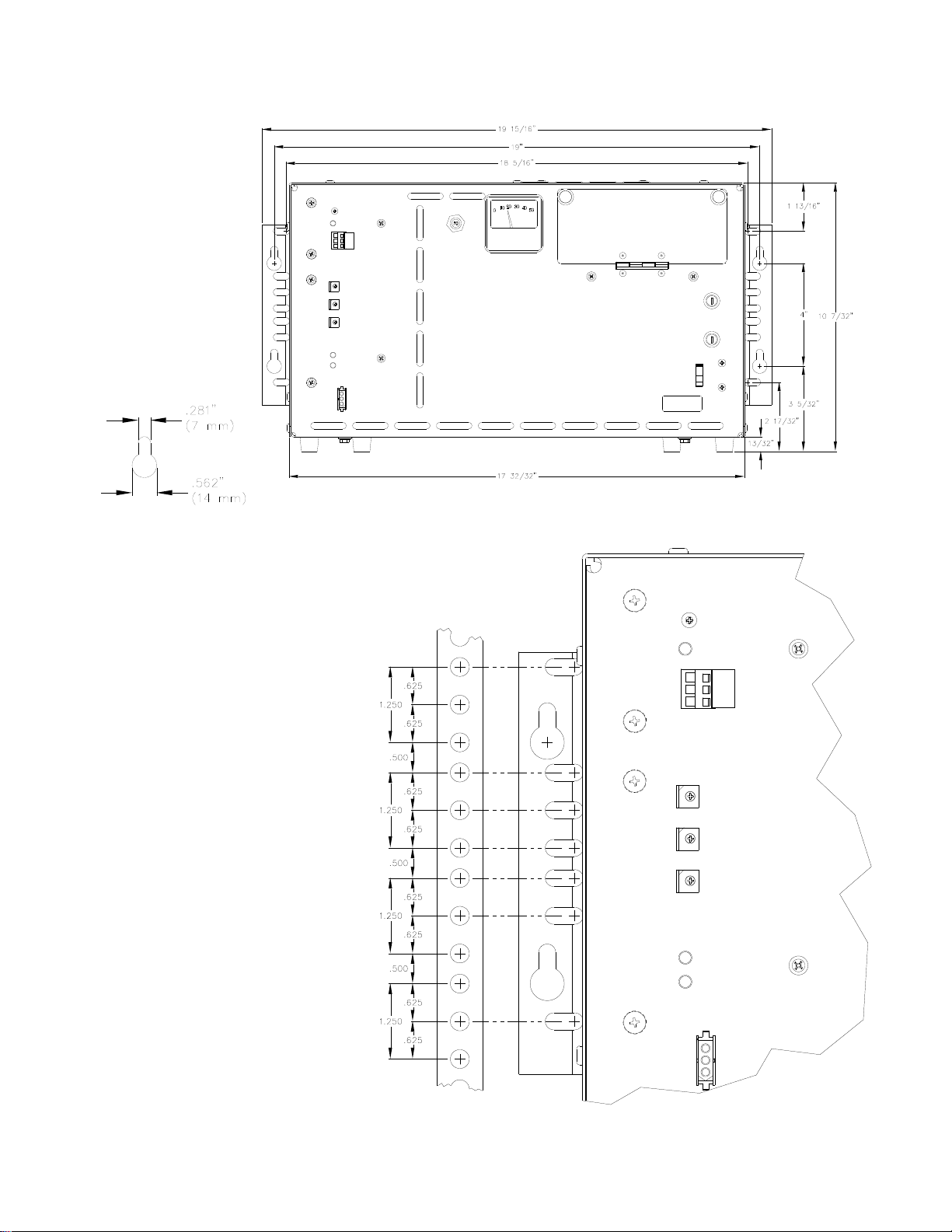
Quarter-inch (1/4") ring terminals are required for
proper connection to the AC input and ground
binding posts (A.A.R.) located on the front of the
charger. Open the small door cover on the front of
the charger by pulling out on the push tabs. Connect
the AC power terminals on the two posts on the right,
as marked on the panel behind the posts. Connect
the AC ground to the terminal lug provided.
WARNING: FAILURE TO PROPERLY
CONNECT THE AC VOLTAGE CONDUCTORS
COULD CAUSE SERIOUS DAMAGE TO THE
CHARGER. BE SURE TO SET THE VOLTAGE
SELECTION SWITCHES ON THE FRONT OF THE
CHARGER TO THEIR PROPER POSITION.
WARNING: DO NOT OPERATE THE
CHARGER WITHOUT PROPER GROUNDING.
IMPROPER GROUNDING CAN RESULT IN THE
RISK OF AN ELECTRIC SHOCK.
6. DC OUTPUT
The DC output wires, are connected on the two left-
most binding posts as labeled on the panel behind
the binding posts (positive on the left and negative
on the right). The DC cables should have quarter-
inch (¼") ring terminals for connecting them to the
binding posts. Check to make sure the polarity of
the DC output wires is the same as those connected
to the battery. The charger will not operate in a
reversed polarity condition. WHEN CONNECTING
THE DC WIRES TO THE CHARGER WITH THE AC
POWER DISCONNECTED, A SPARK MAY
OCCUR. This is caused by the output capacitors
being charged by the batteries. If the DC polarity is
reversed, a circuit breaker will protect the charger
from internal damage. Correct the reversed wires
and push the circuit breaker button back in. Replace
the door cover on the front of the charger after
tightening all of the binding post nuts.
WARNING: DO NOT TOUCH THE
CHARGER'S TERMINALS OR AN ELECTRICAL
SHOCK COULD OCCUR. A VOLTAGE IS
PRESENT ON THE DC TERMINALS EVEN AFTER
THE AC IS DISCONNECTED BECAUSE OF THE
ENERGY STORED IN THE CAPACITOR.
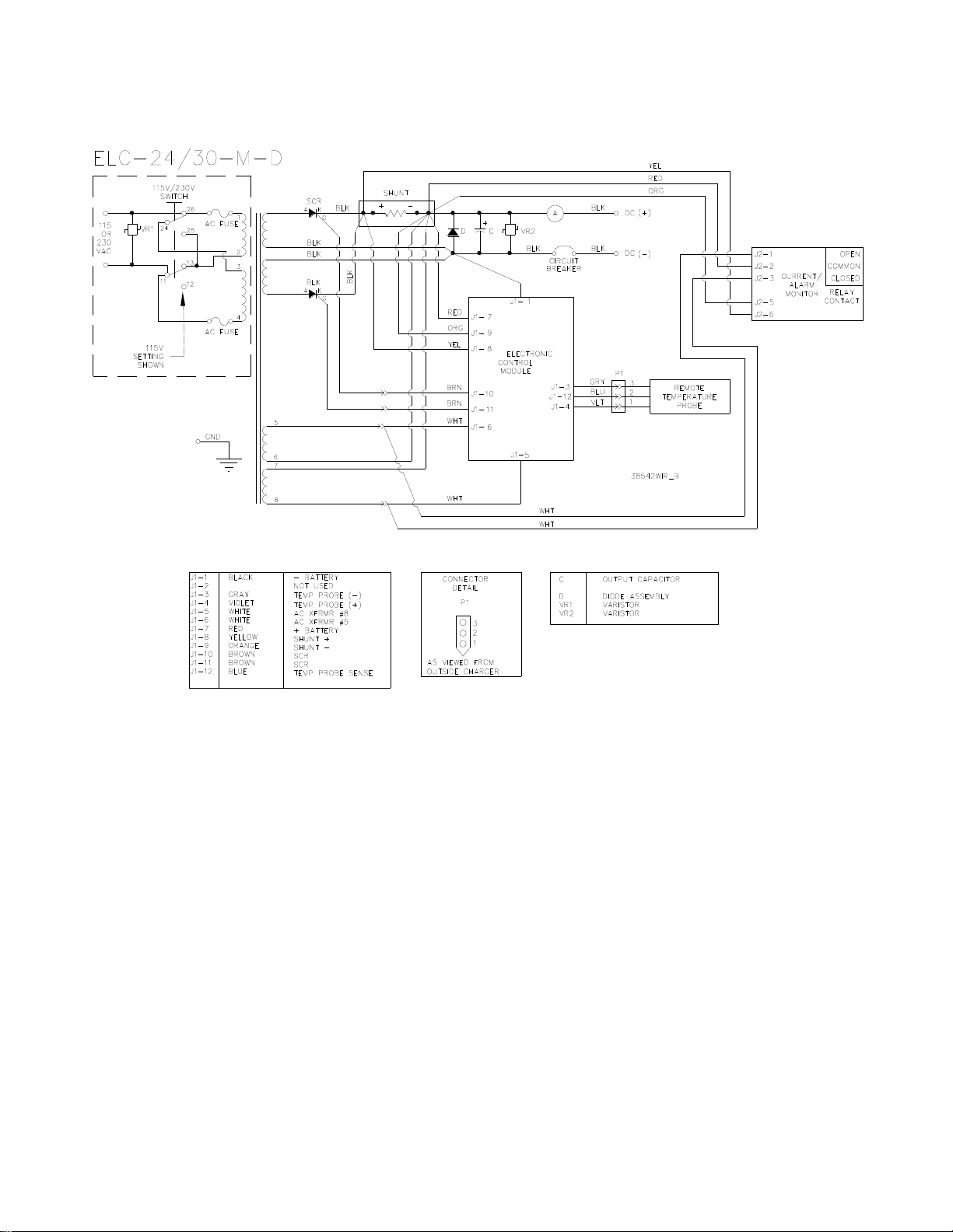
7. TEMPERATURE PROBE
The external temperature probe is an optional way of
extending battery life by using temperature
compensation. One end of the temperature probe
cable has a three-pin plug, which plugs into a
receptacle labeled TEMP PROBE on the front of the
charger. The other end of the cable has the
temperature sensor sealed either in a terminal or
small metal box.
WARNING: IT IS IMPORTANT TO MOUNT
THE TEMPERATURE PROBE ON THE
BATTERIES FOR PROPER TEMPERATURE
COMPENSATION. IF THIS CANNOT BE DONE,
LOCATE THE PROBE AS LOW AS POSSIBLE IN
THE BUNGALOW OR CABINET.
Terminal-Type Probe
The terminal-type probe should be attached to the
negative (-) battery post near the center of the
battery pack. If the threaded stud is long enough
above the battery jumper nut, attach the probe with
another nut. Torque this nut to proper specifi-
cations. If the stud is too short, the nut holding the
jumper wire will need to be removed. Open or
remove the load and charging circuits to the
batteries. Remove the nut holding the jumper and
add the probe, then torque the nut to the proper
specifications. Then close or connect the load and
charging circuits back to the batteries.
Securely fasten the temperature probe cable to
protect the probe from being torn from the
battery. Secure the probe's cable to a fixed object
to ensure the probe will not be pulled loose. Use a
cable tie mount on the battery or on the adjacent
battery, if necessary.
8. OPERATION
The battery charger is adjustable with the three
rotary switches on the front of the charger. The
switches (settable between 20.0 and 35.0) determine
the float voltage for the batteries. SET THE FLOAT
VOLTAGE TO THE BATTERY MANUFACTURER'S
SPECIFIED VOLTAGE FOR 77F. The charger will
then electronically charge the batteries to the voltage
specified on the switches. To set the switches, use
a small screw-driver and turn the switch so that the
arrow head on the slot is pointing to the desired
number. Set the switches in the following manner. If
the desired battery voltage is 26.8 volts, set the top
switch to 2, the middle switch to 6, and the bottom
switch to 8 (see the figure below). This will provide
you with the proper charging voltage. BE SURE
EACH SWITCH IS SET ON A NUMBER AND NOT
BETWEEN NUMBERS. If a switch is set between
numbers, the output current will go to zero and the
yellow charging LED will flash.

www.nationalrailwaysupply.com
1-800-357-3572 5 38542D
Figure 8.1
9. CURRENT MONITOR/ALARM
The ELC-24/30-M-D battery charger includes an
integrated current monitor/alarm that monitors the
output current of the charger. If the charger output
falls below the current limit setting, a green LED
indicator is turned off and a Form C, dry contact
alarm relay is actuated. The current limit
adjustment, LED, and relay terminals are accessible
on the front of the charger (see Figure 9.1).
Figure 9.1
Relay Terminal Remote Wiring
The OPEN, COMMON, and CLOSED relay contacts
have push-in type terminals for remote wiring. The
relay contacts are rated for 1A at 30 Vdc or 0.5A at
120 Vac. A small screwdriver (3/32 inch maximum
blade width) is required to insert or remove a wire
from a relay terminal.
WARNING: BE CAREFUL! IF AN
UNINSULATED METAL TOOL CONTACTS BOTH
THE GROUNDED CHARGER CASE AND A RELAY
TERMINAL PUSH-IN TAB, THIS WILL CAUSE A
POTENTIALLY DAMAGING AND/OR
DANGEROUS ELECTRICAL SHORT.
Current Monitor/Alarm Operation
Table 9.1 outlines the operation of the LED and relay
based on the status of the current monitor. All relay
contact states are with reference to the terminal strip
COMMON.
Current Monitor Status
LED
CLOSED
Relay Contact
OPEN
Relay Contact
Charger output exceeds the current limit setting
On
Closed
Open
Charger output falls below the current limit setting
(and AC power is present at the charger)
Off
(after approx. 30
seconds)
Open
(after approx. 30
seconds)
Closed
(after approx. 30
seconds)
AC power is removed from the charger
Off
(immediately)
Open
(immediately)
Closed
(immediately)
Table 9.1

www.nationalrailwaysupply.com
1-800-357-3572 6 38542D
Current Limit Adjustment
The current limit adjustment should be set to a level
that is below the charger output when sourcing the
minimum DC load of the system and floating the fully
charged battery set. The current limit adjustment is
factory-set to approximately 400 mA (fully
clockwise), which should work for most applications.
If the minimum DC load of the system combined with
the battery float current is above approximately 500
mA, leaving the current limit adjustment at the
factory setting of 400 mA is recommended. If an
adjustment is required, it can be adjusted between
approximately 400 mA and 70 mA. Setting the
current limit adjustment below approximately 100 mA
is not recommended due to internal charger DC
current that can still exist and be monitored if the
charger DC output is disconnected from the load and
battery set.
Adjustment Procedure
A small screwdriver (3/32 inch maximum blade
width) is required to change the current limit
adjustment.
With AC power applied to the charger input and the
charger DC output connected to the load and fully
charged battery set, monitor the charger output
current until it stops decreasing and levels off at the
minimum system current. Ensure that the current
limit adjustment is turned fully clockwise, which will
set the current limit at approximately 400 mA. If the
LED is on and the CLOSED relay contact is closed
when the current limit adjustment is turned fully
clockwise, leave it in that position. If the LED is off
and the CLOSED relay contact is open when the
current limit adjustment is turned fully clockwise, turn
it slowly counterclockwise until the LED turns on and
the CLOSED relay contact closes. Turn the current
limit adjustment approximately 1/8 of a turn
counterclockwise from this switching point. Remove
AC power from the charger to verify that the current
monitor/alarm is functioning. The LED should turn
off and the CLOSED relay contact should open.
Current Monitor Specifications
CURRENT MONITOR/ALARM RELAY CONTACT
RATINGS:
1A at 30 Vdc
0.5A at 120 Vac
TERMINAL CONNECTIONS:
20 –16 AWG wire, strip length of .312 - .359
inches (8 –9 mm)
10. MAINTENANCE
The battery charger requires minimal maintenance.
It should be kept clean and all connections are to be
periodically tightened. BE SURE THE CHASSIS IS
SECURELY GROUNDED. If any problem cannot be
resolved, consult the nearest NRS service agent at
1-800-357-3572.
11. SERVICING
If the battery charger operates improperly, follow the
steps below.
a. Begin by checking the voltage switches to
verify their settings against the specifications
of the batteries.
b. Check the AC voltage selection switch for
the proper setting.
c. Check the fuses to make sure they have not
blown.
d. Check the circuit breaker to see if it has
opened and push it in to reset it, if
necessary.
e. Check the polarity between DC output and
the battery and make sure their connections
are tight.
f. Remove the small cover on the front of the
charger and make sure all of the binding
posts nuts are tight.
g. If the steps above do not solve the problem,
contact your local NRS service agent at
1-800-357-3572.
12. CHARGER SPECIFICATIONS
AC INPUT VOLTAGE:
115 VAC (108-128) or 230 VAC (216-256)
AC INPUT CURRENT:
16.0 amps for 115 VAC (full power)
7.5 amps for 230 VAC (full power)
AC INPUT FREQUENCY:
48 –65 Hertz (single phase)
AC LINE REGULATION:
For a constant output current at 2.23 volts/cell
+ 5.6% for 18 cells
+ 13.1% for 12 cells
AC FUSES:
MDA 12 or equivalent
DC OUTPUT:
Voltage range 20.0 –35.0 + 0.2 volts
Current Maximum 30.0 + 0.5 amps

www.nationalrailwaysupply.com
1-800-357-3572 7 38542D
DC OUTPUT RIPPLE (at battery terminals):
1.4V p-p at 30.0 amps, 24.0 volts
0.28V p-p at 2.0 amps, 26.8 volts
TEMPERATURE COMPENSATION:
3mV per F per cell
WEIGHT, NET:
62 lbs.
DIMENSIONS:
W = 19 15/16" H = 8 7/8" D = 8 3/4"
13. PARTS LIST
The following is a list of parts found in the NRS Model ELC-24/30-M-D. When replacing a part, USE ONLY
ORIGINAL FACTORY REPLACEMENT PARTS of the correct size and rating.
PART NO. QTY. DESCRIPTION
38543S 1 CASE ASSEMBLY MODEL 27570
18696S 1 SHUNT ASSEMBLY
38544S 1 CONTROL MODULE (W/ ELECTRONIC BOARD #21185)
38309S 1 CURRENT MONITOR MODULE (W/ ELECTRONIC BOARD #27545-01)
38308S 1 CURRENT MONITOR MODULE MOUNT
38811S 1 CONTROL CABLE, CURRENT MONITOR
05322S 2 FUSEHOLDER ASSEMBLY
15029S 2 FUSE, 12 AMP
38888S 1 CIRCUIT BREAKER ASSEMBLY
31457S 1 AC SWITCH ASSEMBLY
27319S 1 AMMETER, 50 AMP
14197S 4 BUSHING, 1"
29741S 1 TEMPERATURE TRANSDUCER, 10' (W/ TERMINAL)
29742S 1 TEMPERATURE TRANSDUCER, 30' (W/ TERMINAL)
14742S 1 HEATSINK ASSEMBLY, W/ SCR, 9” WIRE
15194S 1 HEATSINK ASSEMBLY, W/ SCR, 21” WIRE
23074S 1 SCR ASSEMBLY, 50 AMP, 21” WIRE
23073S 1 SCR ASSEMBLY, 50 AMP, 9” WIRE
15032S 2 OUTPUT CAPACITOR, C, 26,000 UF, 55V
38604S 1 CAP ASSEMBLY, W/ DIODE ASSEMBLY
14759S 1 VARISTOR ASSEMBLY, VR2, 130V
31463S 1 TAP STRIP ASSEMBLY
31309S 1 VARISTOR ASSEMBLY, VR1, 320V
31301S 2 DOOR LATCH, BASE
31302S 2 DOOR LATCH, STUD

www.nationalrailwaysupply.com
1-800-357-3572 8 38542D
14. WIRING DIAGRAM
Table of contents
Other NRS Batteries Charger manuals

NRS
NRS ELC-24/30-CVM-D Service manual

NRS
NRS NRS-12 Service manual

NRS
NRS ELC-24/30-D Service manual

NRS
NRS ELC-12/60-CVM-D Service manual

NRS
NRS ELC-12/40-CVM-D Service manual

NRS
NRS ELC 12/40D Service manual

NRS
NRS ELC-12/20-D Service manual

NRS
NRS 21120 VVR 85-60P Maintenance and service guide

NRS
NRS ELC Series Service manual

NRS
NRS ELC-12 User manual