8
Machine Inspection
•After unpacking, Inspect the machine for damage or
missing components. If damage is found, contact the
freight company to le a freight claim.
Before First Use
Battery Installation to be performed by qualied
technician according to the battery connections dia-
gram on the machine (See Marking #2).
• Lift open the Recovery Tank (#21 Figure 1) using
the strap (#32 Figure 4).
• Plug the battery pack connector (#30 Figure 4)
into the mating connector on the machine.
• Install the squeegee, and connect the hose to the
squeegee. See SQUEEGEE INSTALLATION secton.
• Install pads/brushes. See PAD/BRUSH INSTALLA-
TION section.
• Charge the batteries fully. SEE BATTERY CHARGER
SECTION.
• Note: The machine is disabled when the battery
charger is connected to the wall outlet.
MACHINE COMPONENTS
Operator Control Panel
The operator control panel is located at the upper rear
area of the back of the machine. This panel has com-
ponents that control various machine functions.
Wrangler 2012 AB (See Figure 6):
• The key switch (#42) located in the back of the
control box turns the machine on and o. Power
on is indicated when the Battery Meter (#41) is
illuminated.
• The Operator Handles (#39) allow the operator to
control the direction of the machine.
• The Battery Meter (#41) shows the state of charge
of batteries. Fully charged batteries indicated when
the right LED bar is lit. The LED bar will move to
the left as the batteries are discharged. 70% dis-
charge indicated by the second left LED bar ash-
ing. 80% discharge indicated by alternate both left
LED bars ashing.The battery meter is equipped
with a relay that will open, turning o the ma-
chine, when the battery voltage has dropped to its
lowest permissible level.
• The Hour Meter (#41) indicates the hours the
Brush Motor has been used. The hour meter is non
resettable.
• The switch lever (#40) in front of the right control
handle grip (#39) turns on the Brush/Pad Motor
and dispences the solution when the brush/pad
motor switch (#24) is on.
• The Circuit Breaker (#36) controls the Brush/Pad
Motor. Push in to reset.
• The Circuit Breaker (#38) controls the Vacuum
Motor. Push in to rest.
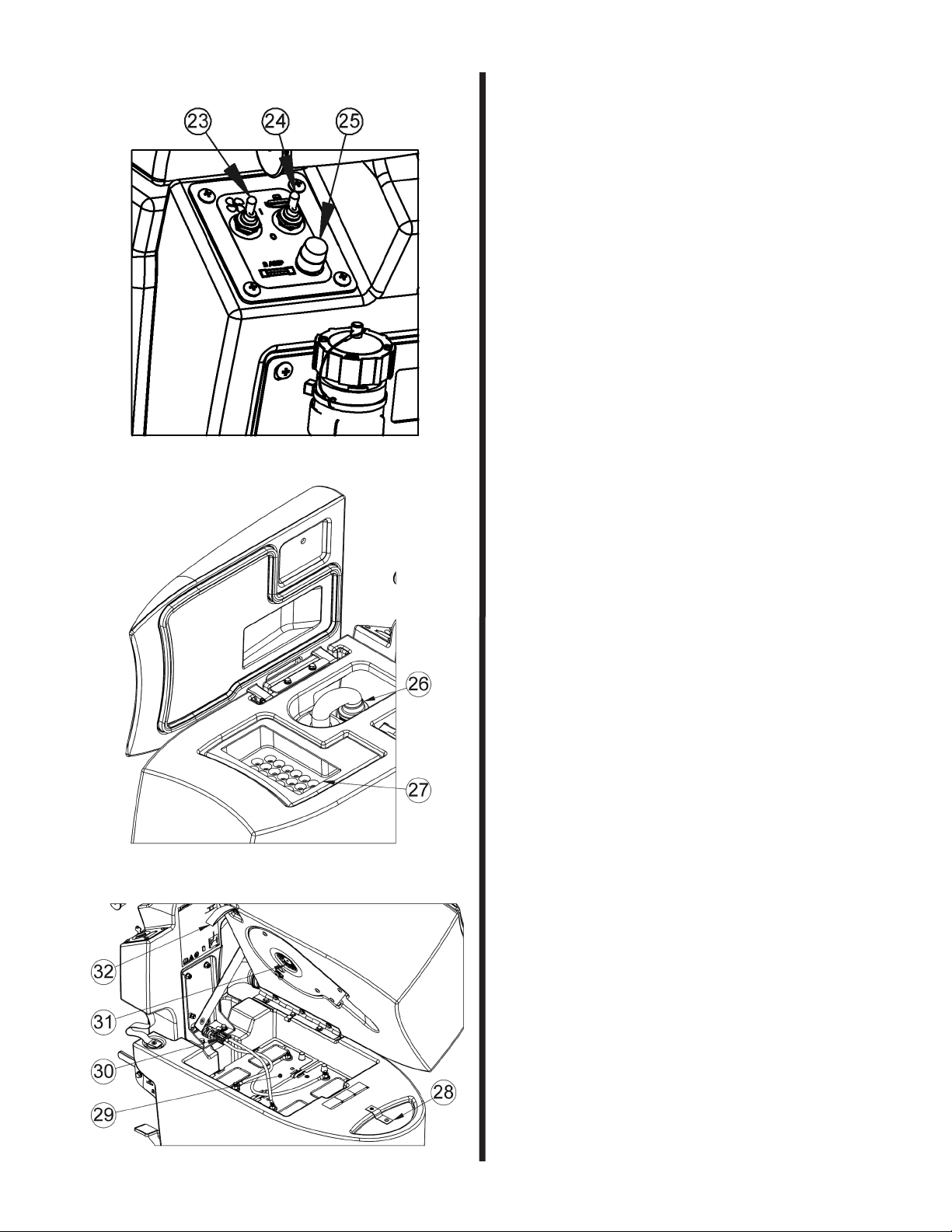
Left Control Panel (See Figure 2.)
• The Vacuum switch (#23) controls the Vacuum
Motor.
• The Brush/Pad Motor switch (#24) controls the
Brush/Pad Motor.
• The Battery Charger Fuse (#25) must be in work-
ing order for the machine to work.
Wrangler 2012 DB (See Figure 5):
• The key switch (#35) located in the right control
panel turns the machine on and o. Power on is
indicated when the Battery Meter (#34) above the
key switch is illuminated.
• The battery meter (#34) shows the state of charge
of batteries during operation. When the batteries
are fully charged, all of the LED’s are illuminated.
As the batteries discharge, the LED’s start to turn
o, one at a time, from right to left. The battery
meter is equipped with a relay that will open, turn-
ing o the machine, when the battery voltage has
dropped to its lowest permissible level. If the ma-
chine is operated until it is automatically shut o,
turn o the key switch, the brush switch, and the
vacuum switch. Then turn on the key switch, and
the machine can be driven to a charging location.
• In the middle of the operator panel are two (2)
rubber twist grips (#33). These grips rotate for-
ward moving and backward to control the direction
and speed of the machine. The farther the grips
are rotated, the faster the machine will move.
These twist grips have a feature that returns the
machine to the neutral position when the handles
are released.
• The Brush/Pad Motor turns on when the brush/pad
switch (#24 Figure 2) is on and the twist grips are
rotated in either direction.
• The solution is dispenced when the brush/pad
switch (#24 Figure 2) is on and the twist grips are
rotated in either direction but does not control the
amount of solution dispenced.
• The Circuit Breaker (#36) controls the Brush/Pad
Motor. Push in to reset.
• The Circuit Breaker (#37) controls the Drive Motor
Controller and the machine. Push in to reset.
• The Circuit Breaker (#38) controls the Vacuum
Motor. Push in to rest.
Left Control Panel (See Figure 2.)
• The Vacuum switch (#23) controls the Vacuum
Motor.
• The Brush/Pad Motor switch (#24) controls the
Brush/Pad Motor.
• The Battery Charger Fuse (#25) must be in work-
ing order for the machine to work.
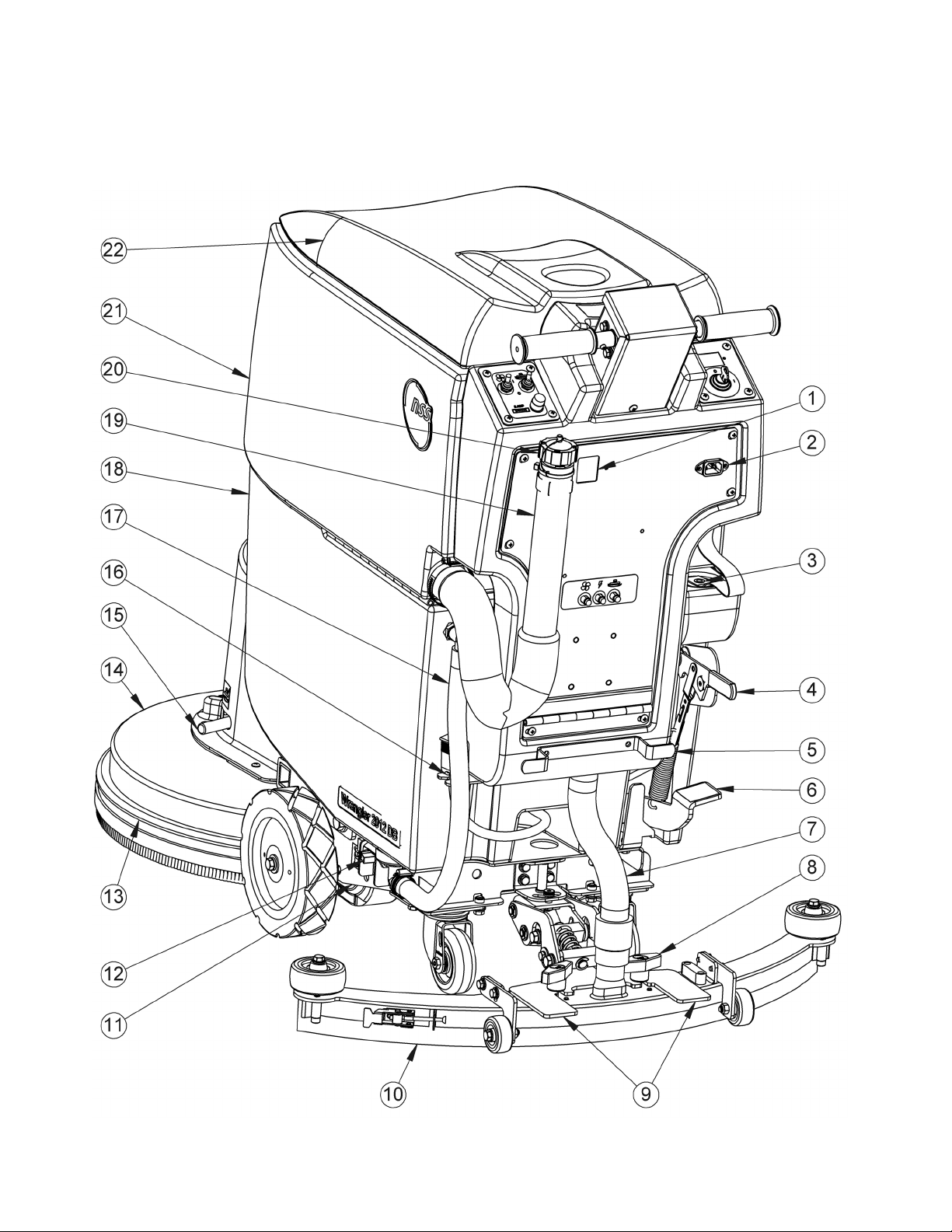
Common Machine Components
(See Figures 1,3 and 4)
Solution Tank
• The solution tank (#18) is the lower part of the
machine body and has a capacity of 12 gal (45 L).
• The solution tank can be lled through the front
ll opening (#28). Lift the cover to access the
opening. Replace cover to prevent splashing when
machine is moving.
• The solution tank can be lled through the rear ll
opening (#3). Lift the plug to access the opening.
Replace the plug to prevent splashing when the
machine is moving.
• The amount of water in the solution tank is seen
in the site gage and drain hose (#17) at the right
rear of the tank. The solution tank can also be
emptied through this hose.
Recovery Tank
• The recovery tank (#21) is the upper part of the
machine body and has a capacity of 14 gal (53 L).
• The recovery tank collects the dirty solution.