NSS eForce 26 User manual

eForce Scrubber 26 & 32
Automatic Floor Scrubber/Dryer
Récureuse/sécheuse de planchers automatique
Fregador y secador de pisos automático
OPERATOR MANUAL
MANUEL DE L’OPÉRATEUR
MANUAL DE OPERADOR

ii
Contents
Markings __________________________________________________ 1
Figure 1 ___________________________________________________ 2
Figure 2 ___________________________________________________ 3
Figure 4 ___________________________________________________ 4
Figure 3 ___________________________________________________ 4
Figure 5 ___________________________________________________ 4
Figure 9 ___________________________________________________ 4
Figure 6 ___________________________________________________ 4
Figure 7 ___________________________________________________ 4
Figure 8 ___________________________________________________ 4
Figure 10 __________________________________________________ 4
Figure 11 __________________________________________________ 4
Figure 12 __________________________________________________ 5
Figure 13 __________________________________________________ 5
Figure 15 __________________________________________________ 5
Figure 14 __________________________________________________ 5
IMPORTANT SAFETY INSTRUCTIONS ____________________________ 6
Battery Safety Information ____________________________________ 7
Battery Charging Safety_______________________________________ 7
GROUNDING OF ELECTRICAL EQUIPPMENT - BATTERY CHARGER _______ 7
Markings __________________________________________________ 8
Unpacking Instructions _______________________________________ 8
Before First Use _____________________________________________ 8
Machine Elements ___________________________________________ 9
Controls ___________________________________________________ 9
Battery Charger _____________________________________________10
Operating Instructions _______________________________________10
User Maintenance ___________________________________________11
Detergent Dispensing System __________________________________13
Troubleshooting_____________________________________________14
Service Codes_______________________________________________14
Battery Charger Error Codes ___________________________________15
Performance Specications ____________________________________16
Technical Specications_______________________________________17
Batteries __________________________________________________18
Battery Charger _____________________________________________18
Transporting _______________________________________________18
Scrapping__________________________________________________18
Technical Repair Manual ______________________________________18
FRANÇAIS _________________________________________________20
ESPAÑOL __________________________________________________34

Marking #1
Marking #2
Marking #3
Marking #4
Marking #5
Marking #6
Marking #7
Marking #8
Marking #9
Marking #10
Marking #11
Marking #12
Marking #13
Marking #14
Markings
Marking #15
Marking #16
Marking #17
Marking #18
1

2
12 13
Figure 1
6
7
8
9
10
11
14
12
3
45
33
32
26
31
27
29
28
15
16
17
36
40 30
34
35

19
18
20
21
22
23
Figure 2
37
25
24
38
39
3

Figure 3
Figure 4 Figure 5
Figure 6
Figure 7
Figure 8
Figure 9
40
41
42
43
44
45
46
47
48
49
50
51
52
53
54
57
56
55
59
58
Figure 10
70
74
73
71
72
75
76 77 78
Figure 11
85
84
83
82
81
80
4

Figure 14
91
90
Figure 15
92
93
Figure 12
Figure 13
5

6
ORIGINAL INSTRUCTIONS (EN)
IMPORTANT SAFETY INSTRUCTIONS
WARNING Read these original
instructions prior to initial use of the appli-
ance/machine.
Safety Instructions
This appliance has been approved for use on
surfaces with gradients up to 10%.
Safety Equipment
This appliance is equipped with devices to protect the
user, and must not be rendered inoperable or by-
passed.
Emergency Stop Button
To halt all functions immediately, press the emergency
stop button.
•The machine will come to a sudden halt.
•All functions will stop.
•Twist the emergency stop button to return it to nor-
mal operation.
Operator Presence Device
•Disables drive functions if the user is not seated on
the machines seat.
Symbols used in these instructions
DANGER – Immediate danger that can cause
severe injury or even death.
WARNING – Possible hazard that could lead to
severe injury or event death.
CAUTION – Possible hazard that could lead to
mild injury or damage to property.
Electrical shock hazard.
Read the Operator Manual.
No smoking, open ames, or sparks near the
batteries.
Batteries - acid and hydrogen gas.
Poison. Causes severe burns. Avoid contact.
Recycle packaging.
Dispose of equipment through suitable collection
systems.
Intended Use
The eForce Scrubber is intended for commercial use,
for wet cleaning of level oors in an indoor environ-
ment, for example in hotels, schools, hospitals, facto-
ries, shops, oces and rental businesses. The clean-
ing settings can be adjusted to suit the cleaning task.
Water quantity, pressure applied to the pads/brushes,
pad speed, vacuum level, driving speed, and detergent
ratio (if equipped) can be adjusted by the user.
Important Safety Instructions
ALL REPAIR SERVICE MUST BE PERFORMED BY AN
NSS AUTHORIZED DISTRIBUTOR OR SERVICE STA-
TION USING ONLY NSS ORIGINAL EQUIPMENT PARTS.
Use this appliance only as directed
in these operating instructions.
•This machine is not intended for use by persons
(including children) with reduced physical, sensory or
mental capabilities, or lack of experience and knowl-
edge.
•Children should be supervised to ensure that they do
not play with the appliance.
•WARNING Operators shall be adequately instructed
on the use of this machine.
•This machine is only to be used for the cleaning of
hard surfaces that are not sensitive to moisture or
polishing operations.
•CAUTION This machine is for inside use only.
•CAUTION This machine shall be stored indoors in a
dry, cool area.
•CAUTION Turn o key switch before changing pads/
brushes.
•Operating temperature range: 40°- 104°F (5° - 40°C)
•This machine is not suitable for cleaning frozen sur-
faces (cold storage).
•Do not operate this machine in water exceeding 3/8
in (1 cm) depth.
•Use only OEM accessories and spare parts.
•This machine is not intended for use in public trac
routes/roads.
•Do not use this machine on surfaces that are sensi-
tive to pressure. See surface pressure loading in the
technical data.
•Do not use this machine in potentially explosive envi-
ronments.
•Do not suck up ammable gases or liquids, undiluted
acids or solvents. This includes gasoline, thinning
agents or hot oil that can form an explosive mixture
when mixed with air. Do not use acetone, undiluted
acids or solvents.
•Orange oil (D-limonene) is not compatible with the
plastics used in this machine. Use of D-limonene may
result in damage to the machine.
•NEVER attempt to operate this machine if it is not
working properly or has been damaged in any way.
•NEVER disconnect or modify any switches or safety
devices (circuit breaker).

7
•NEVER drop or insert any object into any machine
opening.
•NEVER operate this machine with any air opening
blocked. Keep all air openings free of dust, lint, hair,
etc.
•NEVER pick up anything that is burning or smoking,
such as cigarettes, matches or hot ashes.
•ALWAYS keep face, ngers, hair or any other body
part or loose clothing away from any machine opening
or moving part (revolving brush, pad driver, or vacuum
motor).
•ALWAYS turn the machine o when attaching pads or
brushes.
•ALWAYS remove keys when this machine is left unat-
tended.
•ALWAYS be sure that the ramp is secured to the ve-
hicle before attempting to load/unload.
•ALWAYS use extreme caution when operating the
machine on a ramp or loading/unloading this machine
into or out of a truck/trailer. Use extreme caution if
the ramp is wet, oily, or covered with cleaning chemi-
cals.
•NEVER stop or turn the machine on a ramp or incline.
•NEVER attempt to climb a grade or operate this ma-
chine on a ramp or incline that exceeds its rating.
•NEVER park or store the machine near a dock, on
ramps, near a furnace, boiler, open ame, or other
high heat source.
•NEVER allow this machine to freeze.
•NEVER expose the machine to rain, snow, or extreme
temperatures.
•NEVER store any items on this machine.
Battery Safety Information
•WARNING – Failure to observe these warnings can
cause personal injury to machine operator or by-
standers.
•WARNING – Batteries emit hydrogen, which can
cause re or explosion.
•Never smoke, light a match, or cause a spark during
operation or charging.
•Always charge in a dry, well-ventilated area away
from open ame.
•ALWAYS read and understand all instructions before
charging batteries.
•NEVER attempt to charge batteries unless you have
been trained to do so.
•NEVER allow an untrained person to install or charge
batteries.
•ALWAYS wear eye protection and protective clothing
to avoid contact with battery acid.
•NEVER lay anything on top of batteries as arcing
may occur.
•IF CONTACT WITH BATTERY ACID OCCURS, follow
these instructions:
• SKIN – rinse area with water.
• EYES – Flush with water for 15 minutes.
• INTERNAL – Drink water or milk. Follow with Milk
of Magnesia, beaten egg or vegetable oil. Call a
physician immediately.
Battery Charging Safety
WARNING: Unplug battery charger from
wall outlet before disconnecting batteries from ma-
chine to prevent arcing or machine damage.
ALWAYS charge the batteries with upper body open.
• ALWAYS read instructions carefully.
• ALWAYS use the NSS supplied charger with proper
voltage rating.
• ALWAYS plug the charger into an earthed socket
outlet.
• NEVER operate charger if the AC supply cord is
damaged, or if the charger has been damaged in
any way.
• NEVER charge a frozen battery.
• For ooded lead acid batteries (does not apply to
sealed maintenance free batteries):
• ALWAYS check to ensure the battery water level
covers the battery plates before charging.
• ALWAYS check water level after charging and
add distilled water if necessary to bring level to
the bottom of the ll hole.
•
• NEVER overll batteries as battery and machine
damage may result.
• ALWAYS wipe any acid from the top of batteries
using a soap solution.
• ALWAYS reattach caps to batteries. Do not
charge with caps loose or removed.
• ONLY use distilled water.
GROUNDING OF ELECTRICAL
EQUIPPMENT - BATTERY CHARGER
WARNING: Improper connection of the
equipment–grounding conductor can result in a risk
of electric shock. Check with a qualied electrician or
service person if you are in doubt as to whether the
outlet is properly grounded. Do not modify the plug
provided with the charger. If outlet is not suitable for
safe use; have a properly grounded outlet installed by
a qualied electrician.
North America: Always use a properly grounded
3-wire extension cord, which has male and female
plugs. If 25 foot [7.6m] extension cords are used, the
electrical carrying capacity should be no less than 14-3
ST, 50 foot [15.2m] extension cords no less than
12-3 ST.
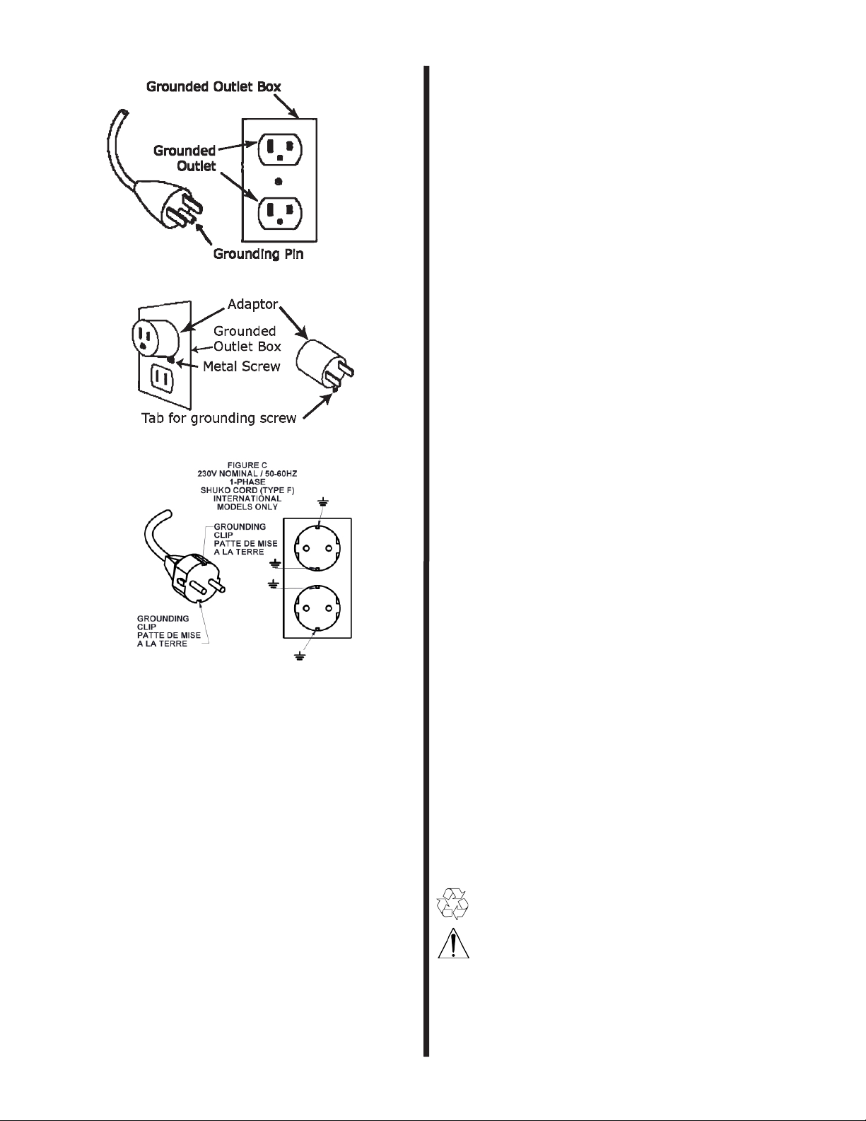
Grounding Instructions
This charger shall be grounded while in use to protect
the operator from electric shock. The charger is pro-
vided with a three-conductor cord and a three-contact
grounding type attachment plug. The plug must be
plugged into an appropriate outlet that is properly in-
stalled and grounded in accordance with all local codes
and ordinances. The green conductor in the cord is
the ground wire. Never connect this wire to other
than the grounding pin of the attachment plug.
If the cord provided with the charger has an attach-
ment plug as shown in Figure A. below, it is intended
for use on a nominal, 120-volt circuit. If a properly
grounded receptacle as shown in Figure A is not avail-
able, an adapter may be installed as shown in Figure B
if the outlet box that houses the receptacle is ground-
ed. Be sure to fasten the grounding tab (the green
colored rigid ear, lug or the like extending from the
adapter) with a metal faceplate screw.
If the cord provided with the charger has an attach-
ment plug as shown in Figure C, it is intended for
use on a nominal 240-volt circuit (single phase only).
Changes to the attachment plug or use of adaptors to
other plug types must be done in accordance with local
regulations.

8
Figure A
Figure B
NOTE: In Canada, the use of a temporary adaptor is
not permitted by Canadian electrical code, C22.1.
Markings
#1 This product may contain a chemical known to the
state of California to cause cancer, or birth defects or
other reproductive harm
#2 Battery Safety Information Label. See Battery
Safety Information in this manual.
#3 Maximum Performance - Press for temporatry
(30s) of maximum scrub deck down force, water ow,
and vacuum.
#4 Clean water strainer, located above dirty water
drain hose.
#5 Warning - To avoid re do not use any ammable
or combustible liquids to clean oors. Do not use in
any explosive atmosphere.
#6 Circuit breaker ON/OFF.
#7 Internal fuse identication - CALL FOR SERVICE.
#8 Touchscreen Calibration Instructions
1. Tap on any screen with two ngers very quick-
ly until a beep is heard, and the screen turns blue.
2. Tap directly on the “+” in the upper right cor-
ner of the blue screen.
3. Tap directly on the “+” in the lower right cor-
ner of the blue screen.
4. Tap directly on the “+” in the lower left corner
of the blue screen.
5. The touch screen will be calibrated and return
to the previous screen you were on.
Note: Not tapping directly on the “+” will not
calibrate the screen and the process will have to be
repeated.
#9 Squeegee Hose storage location, use when squee-
gee is removed from machine.
#10 Clean water valve, located above the dirty water
drain hose.
#11 Squeegee hose plug. Push squeegee end of
hose onto plug when using Solution Drain feature.
#12 Brush motor fuse identication. CALL FOR SER-
VICE.
#13 Charge the batteries with the Upper Body open.
#14 Instructions for pushing the machine - release
the parking brakes:
If the eForce malfunctions and needs to be pushed,
the brakes need to be released. Between the rear
wheels, there are two openings to access the drive
motor brake lever. Move the lever on the joystick side
of the machine up, and the other lever needs to be
rotated down.
Attempting to drive the machine with the brakes re-
leased will result in a 3A code, and the Brake Warning
displayed on the screen. The machine will not move.
Reset the brakes by rotating the lever on the joystick
side down and rotating the lever on the other side up.
#15 WARNING - DO NOT SPRAY LIQUID OR
STORE WET ITEMS IN THIS COMPARTMENT-RISK
OF MACHINE DAMAGE.
#16 Main Circuit Breaker
#17 DO NOT USE JOYSTICK AS A HANDLE WHEN
MOUNTING THE MACHINE. Use the handle at the front
of the arm rest.
#18 WARNING UNPLUG BATTERY CHARGER FROM
WALL OUTLET BEFORE DISCONNECTING BATTERIES
FROM MACHINE TO PREVENT ARCING OR MACHINE
DAMAGE. Unpacking Instructions
(see label on packaging)
1. Carefully cut the (2) bands from around the car-
ton.
2. Remove staples and open top aps.
3. Locate front of machine where the pallet ramp is
taped to the machine.
4. Remove staples at bottom of carton and lift carton
from pallet. CAUTION-Stay clear of front of carton
when lifting carton, the ramp can fall forward.
5. Fold down ramp taking care that it rests complete-
ly and securely on the edge of the pallet.
6. Remove the lag bolts holding the (2) pallet an-
chors to the pallet (7/16in wrench required).
7. Remove and read all operating instructions.
8. Check that the key switch is o.
9. Open the battery compartment.
10. Plug the battery connector into the connector lo-
cated on the underside of the upper body over the
batteries.
11. Check that the circuit breaker (next to the battery
pack connector) is ON.
12. Turn on the keyswitch.
13. Taking care that the casters line up with the ramp,
slowly drive the machine forward o the pallet.
14. Recycle the carton and pallet.
Before First Use
Recycle the packaging.
Battery Installation to be performed by qualied
technician according to the battery connections dia-
gram on the machine (See Marking #2).
• Lift open the Upper Body (#37 Figure 2).
• Plug the battery pack connector (#22 Figure 2)
into the mating connector on the machine.
• Ensure the circuit breaker (#23 Figure 2) is in the

9
ON position.
• Install the squeegee, and connect the hose to the
squeegee. See SQUEEGEE INSTALLATION secton.
• Install pads/brushes. See PAD/BRUSH INSTALLA-
TION section.
• Charge the batteries fully. SEE BATTERY CHAR-
GER SECTION.
• Note the machine is disabled when the battery
charger is connected to the wall outlet.
Machine Elements
See Figures 1 and 2.
1. Key switch. Enables machine operation.
2. Emergency Stop Button.
3. Touch Pad. Use to select machine settings.
4. Maximum performance button. Push for maximum
machine functions for 30 seconds. If desired, push
again to resume selected settings.
5. Joystick.
6. Seat.
7. Seat adjustment lever.
8. Seat belt.
9. Latch.
10. Clean water tank cover.
11. Clean water tank level indicator.
12. Clean water lter.
13. Clean water valve.
14. Dirty water drain hose.
15. Rear Cover.
16. Battery charger cord wrap.
17. Battery charger cord storage.
18. Debris trap.
19. Stand pipe.
20. Clean water tank drain valve.
21. Float.
22. Battery pack connector.
23. Main circuit breaker.
24. Battery charger cover.
25. Batteries.
26. Parking brake release levers.
27. Squeegee.
28. Squeegee release knobs.
29. Blade holding clamp.
30. Squeegee hose.
31. Squeegee hose hanger.
32. Scrub deck.
33. Scrub deck skirt.
34. Pad driver clip.
35. Pad driver lugs.
36. Battery compartment drain.
37. Recovery Tank.
38. Upper Body.
39. Battery Charger WIFI Dongle.
40. Squeegee Bracket.
Controls
Joystick (see Figure 3)
Move the joystick in desired direction of travel. Ma-
chine speed increases with greater movement of the
joystick.
Touch Pad (see Figure 3)
Machine modes and settings are selected using the
touch pad.
Seat Belt Always wear the seat belt when operating
this machine. Touch OK to continue to next screen.
(see Figure 4)
Battery Maintenance Check the electrolyte level in
each cell of the battery pack after charging is com-
plete. Touch OK to continue to next screen. (see
Figure 5)
Operator Missing Indicates no operator sitting on
the seat. (see Figure 6)
Joystick Error Call for service. (see Figure 7).
Brake Error Indicates the parking brakes are manu-
ally disengaged. Move the levers to the normal oper-
ating position. (see Figure 8, and Figure 1 #26)
See Figure 9
Home Screen This screen provides pre-set scrubbing
modes for selection, and displays information including
service codes as outlined below.
40 Charge the Batteries Indicates the battery volt-
age has dropped to minimum value - recharge the
batteries immediately.
41 Maximum Cleaning Mode Touch to select pre-
set settings for heavily soiled oors.
42 Normal Cleaning Mode Touch to select pre-set
settings for general cleaning.
43 Vacuum Only Mode Touch to select pre-set set-
tings for water recovery/vacuum only.
44 Fast/Slow Selection Indicates selected speed
mode.
45 Online Operation Manual Touch to access Op-
eration Manual.
46 Dilution Ratio (if equipped) Displays the se-
lected dilution ratio when using the onboard detergent
dispensing system.
47 Hour Meter Touch to display total hours of use on
scrub motors, vacuum motor, and drive motors.
48 Horn Touch this area to sound the horn.
49 Return to Home Screen Touch to return from
any screen to Home Screen.
50 Low Water Flashes to indicate the clean water
tank has less than 5 gallons (19l) remaining.
51 Double Scrub Mode Touch to select pre-set set-
tings for double scrubbing operations (no vacuum).
52 Detergent Dispensing Setup (if equipped) Touch
to access Ratio Selection and purge functions.
53 Conservation Mode Touch to select pre-set set-
tings for lowest power and water consumption.
54 Service Code Displays error code for service and
troubleshooting. See Troubleshooting Section)
55 3.6 mph (6 km/h) maximum.
56 5.4 mph (9 km/h) maximum.
57 Fast Disabled Indicates fast speed mode disabled
by supervisor.
58 Detergent dispensing o
59 Detergent dispensing on Displays the selected
ratio.
Cleaning Mode Screens
• It is recommended to use Conservation Mode for
daily cleaning. This provides maximum runtime
and minimum water/detergent usage.
From the Home Screen, touch the desired Cleaning
Mode button. The appropriate mode screen is dis-
played, with all settings at default selections.
Any setting can be changed at any time during use.
Touch the buttons to select desired setting.
Green=selected. Gray=OFF/Not Selected.
To turn o a setting (example; turn o water), touch
the Green/selected button. The button will turn Grey.
Turning o the Down Force button, or the Scrub Motor
will raise the scrub deck and turn o the water.
Turning o the Vacuum level will stop the vacuum mo-
tor and raise the squeegee o of the oor.
To end cleaning operations, touch the HOME button
in bottom left corner of the screen, and all cleaning
functins will automatically turn o in the recommended
sequence.
While in Normal Cleaning Mode, the settings as se-
lected are saved when the Home button is touched.
All other cleaning modes - the default settings are
enabled when the mode is selected - user selected set-
tings are not saved.

10
See Figure 10. Normal Mode screen shown.
70 Mode indicator
71 Reset. Touch to reset all settings to selected
mode’s defaults.
72 Water Flow Setting. Touch desired button:
76 Conservation
77 Normal
78 Maximum
73 Scrubbing down force setting, Touch desired but-
ton:
Conservation
Normal
Maximum
74 Scrub motor speed. Touch desired button:
Conservation/Quiet
Normal
75 Vacuum level. Touch desired button:
Conservation/Quiet
Normal
Hour Meter Screen
See Figure 11
80 Hours on both scrub motors displayed here.
81 Hours on left drive motor displayed here.
82 Hours on right drive motor displayed here.
83 Hours on vacuum motor displayed here.
84 Supervisor Settings button.
85 Drain Clean Water (Solution) Tank button. Touch
to turn on vacuum motor without operator in the seat.
Supervise Mode Code Entry Screen
Enter code 1911 to continue to the Supervisor screen.
Supervisor Mode Screen
This screen provides a means to disable certain ma-
chine functions to suit.
Green buttons are available in all cleaning modes.
Grey buttons are disabled in all cleaning modes.
Fast ground speed can be disabled by touching the
speed button until the Fast Disabled is displayed.
Battery Charger
When the machine is supplied with batteries installed,
the battery charger is set by the NSS factory for the
installed batteries.
WARNING-When replacing NSS supplied batteries, or
installing batteries purchased from another source, the
battery charger must be set to the correct curve and
charge current for the batteries being installed.
Do not throw the batteries into the regular waste.
WARNING-The battery charger must always be
set to 24V.
Verifying Battery Charger Settings
• Uncoil the battery charger power cord from the
storage compartment (#17 Figure 1).
• Lift open the Upper Body (#38 Figure 2).
• Locate the battery charger cover, notice it is clear
and the battery charger display is visible.
• Connect the battery charger power cord to an ap-
propriate wall outlet.
• Note the display on the battery charger as it cycles
through the displayed settings:
• SPE (general information).
• 000U (general information).
• 007 (general information).
• 24.0U (THIS IS CHARGING VOLTAGE, MUST
BE 24.0U).
• 30.0A (THIS IS CHARGING CURRENT, VAR-
IES BY CURVE SETTING, SEE CHART BE-
LOW).
• 000c (THIS IS THE CURVE NUMBER SET-
TING, SEE CHART BELOW FOR CORRECT
CURVE).
• Acd (THIS IS BATTERY TYPE, SEE CHART
BELOW)
• Actual battery voltage is displayed.
• Charging current output is displayed.
Battery Charger Curves
Curve
Number Battery Type,
20hr rate Req’d Charge Current
0 Crown wet
>300ah 30A
1 Generic curve
for wet lead
acid
30A for 300+ah 25A
for 200-300ah
2 Crown wet
200-300ah 25A
3 Crown AGM
Batteries 30A for 300+ah 25A
for 200-300ah
4 Generic curve
for wet w/
oat
30A for 300+ah 25A
for 200-300ah
5 Fullriver AGM 30A for 300+ah 25A
for 200-300ah
6 Discover AGM 30A for 300+ah 25A
for 200-300ah
WARNING - Do not use the charger if the set-
tings do not match the battery type and size installed
in the machine. CALL FOR SERVICE
Setting the Battery Charger
The battery charger settings must be changed by a
qualied technician.
See 9098306 Charger Setup leaet (Technician Use
Only) for instructions.
Operating Instructions
See Controls section for description of machine
and control elements.
WARNING-To prevent unauthorized use of the
machine, always switch o the keyswitch and remove
the key when the machine is to be left unattended.
DO NOT PLACE WET RAGS INTO CORD STORAGE
COMPARTMENT FIGURE 1 #17
Squeegee Installation
See Figure 1 #27, #28, #39 & #40.
• Loosen Squeegee Knobs #28.
• Slide the Squeegee under the machine, behind the
scrub deck.
• Lift the squeegee up, and slide it backwards en-
gaging the slots on the squeegee bracket #40.
• Tighten the Squeegee Knobs #28 gently.
• Push the Squeegee Hose into the center hole of
the Squeegee.
Alternative Method
• Sit on the seat.
• Turn on the Keyswitch (Figure 1 #1)
• Acknowledge the warning screens, then touch
Vacuun Only Mode button (Figure 9 #43).
• Once the squeegee bracket has been lowered com-
pletely to the oor, TURN OFF THE KEYSWITCH.
• Dismount the machine, and walk to the right hand
side of the machine.

11
• Pull the squeegee bracket #40 toward the right
side of the machine, lift the squeegee bracket,
and then slide the squeegee under the squeegee
bracket #40.
• Slide the squeegee to engage the slots in the
squeegee bracket #40 (see Figure 1).
• Tighten the Squeegee Knobs #28 gently.
• Push the Squeegee Hose into the Squeegee.
• Sit on the seat, turn on the keyswitch, the squee-
gee will raise to home position.
Pad/Brush Installation
WARNING-Ensure the Scrub Deck is up, and the
keyswitch is OFF.
See Figure 1.
• Lift up the Scrub Deck Skirt (#33).
• Slide the Pad and Pad driver or Brush under the
deck.
• Looking through the slots in the Scrub Deck
(#32), line up the 3 drive lugs with the slots in the
drive plate, and lift the Pad/Brush up.
• Turn the Pad/Brush until it snaps into the clip.
Parking Brake Check
Danger - The parking brake function must al-
ways be checked on a level surface before using the
machine.
• Sit on the seat.
• Check the emergency stop is released.
• Turn on the Keyswitch.
• Read and acknowledge the warning screens by
touching OK.
• Slowly move the joystick a small amount out of
neutral position.
• Listen for an audible click, this is the sound of the
parking brakes disengaging.
• Return the Joystick to the neutral position, and an
audible click must be heard again.
• CALL FOR SERVICE if no clicking sounds are heard.
Driving
DANGER-If the machine does not come to a stop
on a 2% slope, CALL FOR SERVICE, DO NOT USE THE
MACHINE.
Danger of tipping if gradient exceeds 10%. On grades
over 2%, always travel forward or reverse parallel to
the grade.
Danger of tipping on unstable ground - use only on
smooth surfaces.
Danger of slipping on wet oors - drive slowly in slip-
pery conditions.
TO STOP THE MACHINE QUICKLY, RELEASE THE
JOYSTICK. The Joystick will automatically return to
neutral position and halt the machine.
Caution - Always wear the seatbelt.
• Sit on the seat.
• Adjust the seat to a comfortable position (Figure 1
#8)
• Check the emergency stop is released.
• Turn on the Keyswitch.
• Read and acknowledge the warning screens by
touching OK.
• Select the Slow Speed Mode (Figure 9 #55) for
normal use.
• For transport or cleaning in wide open areas, Fast
Speed Mode (Figure 9 #56) can be selected.
• Move the Joystick a small amount in the direction
of desired travel.
• Move the Joystick a small amount to start the
machine’s movement.
• Once movement has started, if the environment
is clear and safe for faster speeds the joystick can
be moved further.
• Moving the Joystick further from nuetral increases
power to the drive wheels permitting greater
speed, and power to climb slopes.
• When turning, it is normal to feel the front cast-
ers swivel.
• Return the Joystick to the neutral position to stop.
• When traveling forward, fastest stops can be
made by pulling the Joystick back to full reverse
position.
Filling the Clean Water Tank
WARNINGS
Do not use ammable liqids.
Only use cleaning detergents free from solvents, hy-
drochloric acid and hydroouric acid.
Follow safety instructions provided with the cleaning
detergents.
Follow detergent manufacturer’s instructions regarding
Personal Protective Equippment.
Do not use high foaming detergents.
See Figure 1 #10 and #11
• Remove the Clean Water Tank Cap #10.
• Fill with water up to the desired level.
• A water level indicator (#11) hangs inside the
tank.
• Pour in detergent if desired according to detergent
manufacturer’s instructions.
• Wipe spilled water/detergent from the machine
surfaces and oor.
• Push the cap securely into the tank opening.
Basic Cleaning Operation
• DRIVE to the area to be cleaned.
• Ensure Slow Speed Mode is selected.
• Touch desired cleaning mode.
• The scrub deck will lower to staged positon.
• The squeegee will lower to the oor.
• Move the Joystick slowly in the desired direction of
travel.
• The scrub deck will start, the vacuum motor will
start, the water pump will start.
• Any setting (water ow, scrub deck down pres-
sure, etc.) can be changed while moving/scrub-
bing. Touch Reset to return to default settings.
• Drive the machine so that all areas of the oor are
cleaned.
• When cleaning is complete, continue driving and
touch the Home button.
• All cleaning functions will automatically turn o
in the correct sequence.
• It is not necessary to stop the machine to touch
Home and end cleaning operations.
• Drive to Draining area.
• After User Maintenance is complete, turn o the
Keyswitch, and charge the batteries.
User Maintenance
Draining/Cleaning the Recovery Tank
Drain and clean after each use.
CAUTION - Do not spray high pressure water
directly onto the electrical cabinet or the batteries.
See Figures 1 and 2.
• Remove the Drain Hose (#14 Figure 1) from the
storage tray.
• Remove the plug by turning the handle counter
clockwise.
• Drain the dirty water in appropriate area.
• Release Latch #9, and lift open the Upper Body

12
(#38 Figure 2).
• Remove and clean the Debris Trap (#18 Figure 2).
• Remove and clean the Float (#21 Figure 2).
• Rinse the Recovery Tank (#36 Figure 2).
• Install the Drain Hose plug, and return the drain
hose to the storage tray.
• Hook the plug’s handle in the provided hole in
the storage tray.
Draining the Clean Water Tank
Do not leave detergent mix in tank for more than
24hrs. Clogging of strainer and lines may result.
See Figures 2, 9 and 11.
• Remove the Clean Water Tank Cap #10.
• Release Latch #9, and lift open the Upper Body
(#38 Figure 2).
• Open the drain valve located inside the recovery
tank (#20 Figure 2).
• Lower the upper body.
• Disconnect the squeegee hose from the squeegee.
• Push the squeegee hose onto the rubber stopper
on the right side of the scrub deck (see Marking
#11).
• From the Home screen, touch the Hour meter
button (#47 Figure 9).
• Touch the Drain Solution button (#85 Figure 11).
The vacuum motor will turn on.
• Allow the vacuum motor to run until all water/so-
lution is evacuated from the clean water tank.
• Touch the Drain Solution button. The vacuum mo-
tor will turn o.
• Touch the Home button to return to the Home
screen.
• Lift open the Upper Body, and close the drain valve
(#20 Figure 2).
• Drain the Recovery tank.
Clean Water Filter Maintenance
Clean the lter weekly
See Figure 1 #12 & #13
• Turn o the Clean water valve #13.
• Unscrew the Clean water lter canister #12.
• Remove and clean the screen.
• Replace the screen into the canister.
• Screw the canister back in place.
• Turn ON the Clean water valve #13.
Squeegee Maintenance
Clean the squeegee and inspect the blades daily.
See Figure 1
• Remove the Squeegee from the squeegee bracket.
• Set the squeegee upside down on the oor or
bench.
• Release the Blade Holding Clamp #29. Note
where to locate the ends of the clamp.
•
• Remove the blades, clean, inspect for wear, re-
place as necessary.
• Set the blades back into the squeegee, with equal
amounts of blade hanging past both ends of the
squeegee housing.
• Replace the Blade Holding Clamp #29.
• Pull slightly on the right end of the rear blade, and
latch the clamp.
Adjusting the Blade Holding Clamp
In case the squeegee blades are being pulled out of
the housing during use:
• Loosen the lock nut on the clamp’s rod.
• Turn the rod in to shorten its adjustment.
• Tighten the lock nut, and resume cleaning.
• Repeat the above as required until the blades
remain in place.
• See image below.
32 Sqeegee Break-Away Tips
The squeege on eForce Scrubber 32 is equipped with
breakaway tips to prevent damage in the event of
excessive impacts.
In the case of a squeegee tip becoming released from
the squeegee, it can be snapped back into place with-
out the use of tools. The procedure is the same for
both tips.
1. Set the band clamp and squeegee blades aside.
2. Push the tip into the slot on the end of the squee-
gee center section.
3. Look thru the two holes to verify proper alignment.
4. Slide the center’s tip into place.
5. Install the squeegee blades.
6. Place the band clamp, and lock the toggle.
7. Install the squeegee back onto the machine, re-
sume cleaning.
Squeegee Adjustment
No adjustment is needed.
Adjustment or repair is necessary if the linkage has
been damaged.

13
The squeege housing top surface must be level with
the oor. If it is not level due to impacts or damage,
CALL FOR SERVICE to adjust the length of the both
top links.
Pads/Brushes
Inspect the pads/brushes for wear daily. Replace as
necessary.
Battery Compartment Drain
See Figure 1 #36
CAUTION - Catch and dispose of battery
acid in accordance with local regulations.
• Drain the battery compartment weekly.
Battery Maintenance
Charge the batteries after each use.
CAUTION: DIFFERENT BATTERY TYPES HAVE DIFFER-
ENT CHARGING REQUIREMENTS. FAILURE TO PROP-
ERLY IDENTIFY YOUR BATTERY TYPE AND SET THE
CHARGER ACCORDINGLY WILL RESULT IN BATTERY
DAMAGE, AND VOID THE WARRANTY.
The battery charger is fully automatic. Simply plug
the charger into a suitable wall outlet, and the charger
will charge the batteries. The green full battery LED
will be continuously illuminated when the charge cycle
is complete.
A bubbling, or boiling sound coming from the batteries
during the last few hours of the charge is normal. The
batteries may be warm, but not too hot to touch.
The charger will maintain the proper battery voltage
as long as it is plugged in (maintenance mode).
Equalizing the batteries (Flooded only)
The batteries should be equalized once every 30 days
for maximum battery runtime and life.
To equalize the batteries:
• Plug in the charger, and fully charge the batteries
(until the green LED is on continuously).
• Unplug the charger from the wall outlet, then plug
it back in.
• The charger will run for ~2hrs, holding the batter-
ies at a constant voltage, and equalizing each cell.
Battery Do’s and Don’ts:
• You do not have to fully discharge the batteries
before charging. They do not have a “memory”.
• Plug the charger in anytime the machine is not in
use.
• NEVER let the electrolyte level fall below the tops
of the plates (ooded cell batteries). This will
damage your batteries almost immediately, and
void the battery warranty. They can tell if this
happened.
• NEVER rell the batteries with well or tap water
(ooded cell batteries).
• NEVER overll the batteries (ooded cell batter-
ies).
• NEVER let the batteries sit discharged overnight
(or between shifts).
• ALWAYS check the electrolyte level about every 3
or 4 charge/discharge cycles BEFORE CHARGING.
• ALWAYS rell the batteries with distilled water (if
needed) AFTER CHARGING.
• ALWAYS fully recharge the batteries after use (un-
til the green LED comes on).
• ALWAYS equalize the batteries (Flooded only) ev-
ery 30 days.
Opportunity Charging
Opportunity charging is charging the batteries when
an opportunity presents itself, such as during breaks,
and is done in addition to a full charge cycle.
Opportunity charging is recommended, as this extra
charging time will help raise the operating voltage of
the batteries, and will help ensure maximum runtime
and cycle life. When opportunity charging, equalize
weekly.
Monthly Maintenance (or every 100hrs)
• Clean the battery terminals.
• Clean the seal between the Upper Body and the
Recovery Tank.
• Grease the front caster axles and swivels.
Washing Instructions
CAUTION - DO NOT SPRAY WATER INTO CORD
STORAGE COMPARTMENT - MACHINE WILL BE DAM-
AGED.
• Wipe down the machine’s exterior surface with a
damp cloth
All other servicing should be performed by an
authorized NSS Service Representative.
Storage
PROTECT FROM FREEZING
Note the weight of the machine in the specicatons
table when selecting a storage location.
Store the machine indoors - 40°- 104°F (5° - 40°C).
Optional Accessory
Detergent Dispensing System
When enabled, the Detergent dispensing system au-
tomatically adds cleaning detergent to the clean water
stream according to the selected ratio.
CAUTION - Always purge the system when changing
cleaning detergents. See purge instructions.
CAUTION - Always store cleaning detergents accord-
ing to the instructions on the cleaning detergent label.
CAUTION - Never use the same container for dierent
cleaning detergents. Observe all regulations regarding
labeling.
A 1 gallon (3.8l) F-style container with 38-400 closure
threads is included with this accessory. The included
special bottle cap can be used on other containers with
matching closure threads. See Figure 15.
Filling the Detergent Container
See Figure 15
• Unscrew the cap and lift out the suction tube.
• Pour ≤1 gal. (3.8l) of cleaning detergent into the
container.
• Clean up any splilled detergent.
• Insert the suction tube, and screw the cap onto
the container. Leave the cap slighly loose to allow
air to enter the container as liquid is pumped out.
• Alternatively, if the cleaning detergent comes in
a container with a 38-400 cap/closure, and ts
the container holder, it can be used in place of the
supplied container.
Turning On the Detergent Dispensing System
• From the Home screen, touch the Detergent Dis-
pensing Setup button (#52 Figure 9).
• Touch the appropriate ratio button according to
the dilution or mixing ratio specied on the clean-
ing detergent’s label. Touching a ratio button will
turn the button Green, and enable the detergent
dispensing system.
See Figure 14.
90 Ratio selection buttons.
91 Prime/Purge botton.
Priming Instructions
Priming will dispense water and cleaning detergent
onto the oor. Always prime the system in an area
where the oor surface will not be damaged by undi-
luted cleaning detergent.
Always prime the detergent dispensing system before

14
rst use, or after removing the cap from the container.
• From the Home screen, touch the Detergent Dis-
pensing Setup button (#52 Figure 9).
• Touch the Prime/Purge button (#91 Figure 14).
The water pump and detergent pump will run for
10 seconds.
• Watch the tubing from the container. Touch the
Prime/Purge button as many times as required to
see all air bubbles have been pumped from the
tubing.
• Touch the Home button to return to Home screen.
Purging Instructions
• Remove the container of detergent no longer being
used.
• Attach the suction hose/cap to a container of clean
water.
• Touch the Prime/Purge button (#91 Figure 14).
Repeat touching the Prime/Purge button until all of
the detergent is ushed out of the system.
• Touch the Home button to return to Home screen.
Turning O the Detergent Dispensing System
• From the Home screen, touch the Detergent Dis-
pensing Setup button (#52 Figure 9).
• Touch the selected (Green) ratio button. The but-
ton turns Grey, and the system is now OFF.
• Touch the Home button to return to the Home
screen. Troubleshooting
Problem Cause Solution
Machine will not
turn on -Batter pack not
connected.
-Battery charger
is on.
-Batteries dis-
charged.
-Circuit breaker
tripped
-Connect the
battery pack.
-Unplug the
charger.
-Charge the
batteries.
-Reset the cir-
cuit breaker
Machine does
not pick up
water
-Recovery tank
full.
-Float ball
stuck.
-Squeegee hose
or standpipe
plugged.
-Squeegee hose
not connected.
-Squeegee
blades worn.
-Squeegee
blades loose.
-Hole in squee-
gee hose.
-Vacuum motor
fuse blown.
-Squeegee link-
age damaged.
-Drain recovery
tank.
-Clean oat
screen and ball.
-Clear squeegee
hose and stand-
pipe.
-Connect
Squeegee hose.
-Flip or replace
blades.
-Adjust latch on
band clamp.
-Replace squee-
gee hose.
-Call for service.
-Call for service.
No water ow -Clean water
lter clogged.
-Water valve
closed.
-water pump
fuse blown.
-clean the lter/
screen.
-Turn on valve
-Call for service.
Water leaks on
oor with ma-
chine o
-Dispensing
Valve dirty or
damaged.
-Call for service.
Problem Cause Solution
Run time is less
than when new -Batteries dam-
aged due to low
electrolyte.
-Battery termi-
nals dirty.
-Batteries not
being fully
charged.
-Batteries worn
out.
-Fill each cell
with distilled
water, charge,
check for im-
provement.
-Clean the ter-
minals.
-Allow char-
ger to nish
charging before
unplugging.
-Replace batter-
ies.
Uneven cleaning -Pad/Brush
worn out.
-Scrub deck/
linkage dam-
aged.
-Replace pads/
brushes.
-Call for service.
Detergent not
dispensing (if
equipped)
-Lines plugged.
-Detergent
container under
vacuum.
-Detergent
pump squeeze
tube worn.
-Pump fuse
blown.
-Purge lines
with water.
-Loosen cap
slightly.
-Call for service.
-Call for service.
Service Codes
CODE MEANING SOLUTION
12 Parameter data
is corrupt. Turn keyswitch o
then on. If code
reappears call for
service.
2D Low battery Check battery volts,
terminals, con-
nections. Repair
as needed, charge
batteries. Call for
service.
21 Low battery
voltage protec-
tion reached
Charge the batteries.
22 High battery
voltage protec-
tion.
Turn o machine, let
stand for 1hr. Call for
service.
23 High controller
temperature. Turn o machine, al-
low to cool. Call for
service.
26 Precharge
failure during
power up.
Check battery volts,
terminals, con-
nections. Repair
as needed, charge
batteries. Call for
service.
29 Bad null current
drive. Check wiring. Turn
keyswitch o and on.
Call for service
2A Bad null current
Brush. Check wiring. Turn
keyswitch o and
on. Call for service if
problem persists.

15
CODE MEANING SOLUTION
32 Solenoid weld-
ed. Caused by
wiring short
circuit in con-
tactor wiring or
contactor coil.
Internal control
system check
failure.
Check wiring and
solenoids. Turn
keyswitch o and
on. Call for service if
problem persists.
33 Solenoid did not
close. Caused
by wiring short
circuit in con-
tactor wiring or
contactor coil.
Internal control
system check
failure
Check wiring and
solenoids. Turn
keyswitch o and
on. Call for service if
problem persists.
37 Throttle fault.
Internal control
system check
failure.
Check joystick and
wiring. Turn machine
o and then on. If
problem continues
call for service
36 Right brake
overcurrent Call for service.
39 Left brake over-
current Call for service.
3A Right brake
circuit open Turn on brake lever
then turn machine o
and then on. If prob-
lem continues call for
service.
40 Left brake cir-
cuit open Turn on brake lever
then turn machine o
and then on. If prob-
lem continues call for
service.
F42 The brush mo-
tor or a drive
motor is ex-
ceeding the cur-
rent limit set in
the controller.
Select lower pad
pressure setting.
Check brakes. Turn
machine o and then
on. If problem contin-
ues call for service.
44, 4C,
45, 59, 60 Caused by wir-
ing short circuit
in drive wiring
or shorted drive
motor. Carbon
brushes need
service.
Check wiring and
drive motor for short
circuit. Correct prob-
lem if found. Check
carbon brushes. If
problem continues
call for service.
4D, 46, 61 Caused by wir-
ing short circuit
in brush wir-
ing or shorted
brush motor.
Carbon brushes
need service.
Check wiring and
brush motor for short
circuit. Check car-
bon brushes. Correct
problem if found. If
problem continues
call for service.
58 The deceleration
of the brush
motor or drive
motor exceeded
set parameters.
Example: Tried
to slow down
or stop on too
steep a hill.
Turn machine o and
then on. If problem
continues call for
service.
CODE MEANING SOLUTION
62 Wired incor-
rectly. Internal
control system
failure.
Check wiring. Turn
machine o and then
on. If problem contin-
ues call for service.
63 Caused by wir-
ing short circuit
in contactor wir-
ing or contactor
coil.
Check wiring and con-
tactor for short cir-
cuit. Correct problem
if found. If problem
continues call for
service.
Battery Charger Error Codes
Always conrm the battery charger settings match the
batteries installed if an error code is displayed.
If any error codes are displayed:
• Unplug the charger.
• Check the battery connections are clean and tight.
• Check the electrolyte level in each cell (ooded
batteries only).
• Try charging again. First charge on new batteries
may result in a code.
Code Meaning
E01 Max battery V reached. Verify charger is set
to match the installed batteries
E02 Charger maximum internal temperature
reached. Charge with Upper Body open, and
Storage Compartment cover open.
E031 Phase 1 safety timer 18h reached. Batteries
need replaced.
EDI Phase 1 battery voltage failed to rise. If
batteries are new charge again, otherwise
replace the batteries.
E032 Phase 2 safety timer 10hr reached. If bat-
teries are new, try charging again. If batter-
ies are >1yr old they need replaced
EDU Phase 2 batteries require excessive current
to hold voltage. If batteries are new charge
again, otherwise replace the batteries.
SCt Overall Safety Timer. Replace the batteries.
Srt Charger internal short - replace the charger.

16
Performance Specications
eForce 26 eForce 32
Cleaning Path mm
(in) 660
(26) 813
(32)
Ø Pad/Brush mm
(in) 330
(13) 406
(16)
Squeegee
Width mm
(in) 876
(34.5) 1084
(42.7)
Clean Water
Capacity l
(gal) 94.6
(25)
Recovery Tank
Capacity l
(gal) 102
(27)
Scrub Deck
Down Force kg
(lb)
32 (70)
50 (110)
68 (150)
36 (80)
54 (120)
73 (160)
Pad/Brush
Speed 150
Solution Flow
Rate l/min
(gpm)
Conservation (26): 0 - 1.1 (0.30)
Conservation (32): 0 - 1.5 (0.4)
Normal: 0 - 2.8 (0.75)
Maximum: 0 - 3.8 (1.0)
Water Usage
Conservation
Mode
m2/l
(ft2/gal) 60
(2444)
Recovery
Vacuum kPa
(in H2O) 15.2
(61)
Recovery
Airow l/s
(cfm) 40.8
(88)
Min Aisle Turn-
Around mm
(in) 1575
(62) 1626
(64)
Max
Speed km/h
(mph) Slow 6 (3.6)
Fast 9 (5.4)
Maximum
Working Grade % 10
Runtime h235ah: 3.2
350ah: 4.3
Brush Motor
Power W
(hp) 380
(.51)
Vacuum Motor
Power W
(hp) 470
(.63)

17
Technical Specications
eForce 26 eForce 32
Width
(excl. squee-
gee)
mm
(in) 699
(27.5) 851
(33.5)
Height mm
(in) 1321
(52) 1321
(52)
Length mm
(in) 1422
(56) 1422
(56)
GVW
kg
(lb) 587
(1294) 594
(1309)
EMPTY
kg
(lb) 231
(510) 238
(525)
TRANSPORT
kg
(lb) 422
(931) 429
(946)
°C
(°F) 5-40
(40-104)
Protection
Rating IPx3
V24
Hz __
---
Rated Power W 1910
Brush Motor
Power W
(hp) 380
(.51)
Vacuum Motor
Power W
(hp) 470
(.63)
Wheel
Pressure on
oor
N/mm2
(lb/in2)Rear 0.5 (67)
Front 1.6 (231)
EN/UL 60335-2-72
Sound pres-
sure level LpA
dB(A) ≤70
Sound power
level LWA+KWA
dB(A) 85
Vibration-
Hand-arm m/s2≤2.5
Vibration-
Whole body m/s2≤0.5
Stopping
Distance m
(ft) <1.71
(5.61)

18
Batteries
Batteries Qty Volts Ah
(20hr)
Standard Battery 4 6 235
Max. Battery 4 6 350
Battery Compartment
Dimensions
length x width x height
mm (in)
673 x 375 x 375
(26.5 x 14.8 x 14.8)
Battery Charger
Feature Rating
Input Ratings 115/240V 50-60Hz 12A max
Output Ratings 24 or 36VDC, 25A or 30A
# of charge curves 7
Curve Selection via WIFI smart device APP
Regulatory cULus, CE, CEC, CB Report
Transporting
• Note the size and weight of the machine listed in
the Technical Specications.
• Slots/holes are provided in the frame for attaching
tie down straps. See Figures below.
Scrapping
Contact a qualied scrapping service provider to dis-
pose of the machine.
Ensure the following materials are scrapped according
to the Laws in force:
• Batteries
• Plastic containing components
• Electrical and electronic components
Technical Repair Manual
9098304 eForce Scrubber Technical Repair Manual is
available for download to Distributors and Authorized
service centers through the NSS Proxx portal.
http://www.nss.com/distributors_service_centers.php
This manual suits for next models
1
Table of contents
Languages:
Other NSS Scrubber manuals

NSS
NSS champ 2929 rb User manual

NSS
NSS WRANGLER 2616 DB User manual

NSS
NSS CHAMP ZS 35 User manual

NSS
NSS Wrangler 3330 DB User manual

NSS
NSS WRANGLER 1708CB User manual

NSS
NSS Rally 55 User manual

NSS
NSS Wrangler 3330 DB User manual

NSS
NSS CHAMP 2417 RB User manual

NSS
NSS Wrangler 2012 AB User manual

NSS
NSS WRANGLER 1708CE User manual
Popular Scrubber manuals by other brands

Donaldson
Donaldson BOFA DustPRO 100 user manual

Miller
Miller Filtair 130 owner's manual

Hammerhead
Hammerhead 500 Series Adjustment & Testing Guide

Advance acoustic
Advance acoustic SC450 Instructions for use

Pacific Floorcare
Pacific Floorcare S-28HD Parts & operating manual

Fimap
Fimap IMx instruction manual