NTI VOPEX-C5VA-xC1000 User manual

MAN186 Rev Date 12/13/2012
VOPEX-C5VA-xC1000
Video/Audio
Splitter/Extender
Installation and Operation Manual
(Receiver not included)
VOPEX®Series

i
Crimp-on
Solder
terminal
TRADEMARK
VOPEX is a registered trademark of Network Technologies Inc in the U.S. and other countries.
COPYRIGHT
Copyright © 2003, 2012 by Network Technologies Inc. All rights reserved. No part of this publication may be reproduced, stored
in a retrieval system, or transmitted, in any form or by any means, electronic, mechanical, photocopying, recording, or otherwise,
without the prior written consent of Network Technologies Inc, 1275 Danner Drive, Aurora, Ohio 44202.
CHANGES
The material in this guide is for information only and is subject to change without notice. Network Technologies Inc reserves the
right to make changes in the product design without reservation and without notification to its users.
WARNING: Never connect a VOPEX Series VOPEX-C5VA-xC1000 Extender/Splitter to an Ethernet card,
Ethernet router, hub or switch or other Ethernet RJ45 connector of an Ethernet device. Damage to devices connected
to the Ethernet may result.
Note: CAT5 connection cable used between NTI VOPEX Splitter and XTENDEX Series Remote should not be run
underground, outdoors or between buildings.
WARNING: Outdoor or underground runs of CAT5 cable could be dangerous and will void the warranty.
GROUNDING
This product is equipped with grounding hardware to prevent interference from sources of
electrical noise that could interfere with the normal operation of the VOPEX or damage it.
Use either the crimp-on lug or solder terminal to secure a properly grounded wire to the
VOPEX.
!
!

ii
TABLE OF CONTENTS
Introduction......................................................................................................................................................................1
Materials..........................................................................................................................................................................1
Features and Functions...................................................................................................................................................2
Limitations .......................................................................................................................................................................3
Preparation for Installation ..............................................................................................................................................3
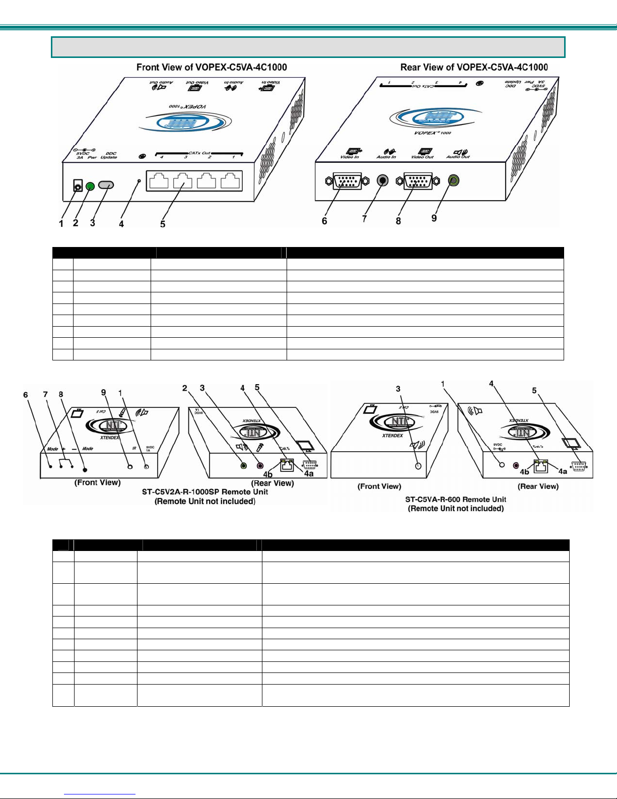
VOPEX Installation..........................................................................................................................................................4
VOPEX-C5VA-xC1000................................................................................................................................................4
Remote Unit Installation..................................................................................................................................................6
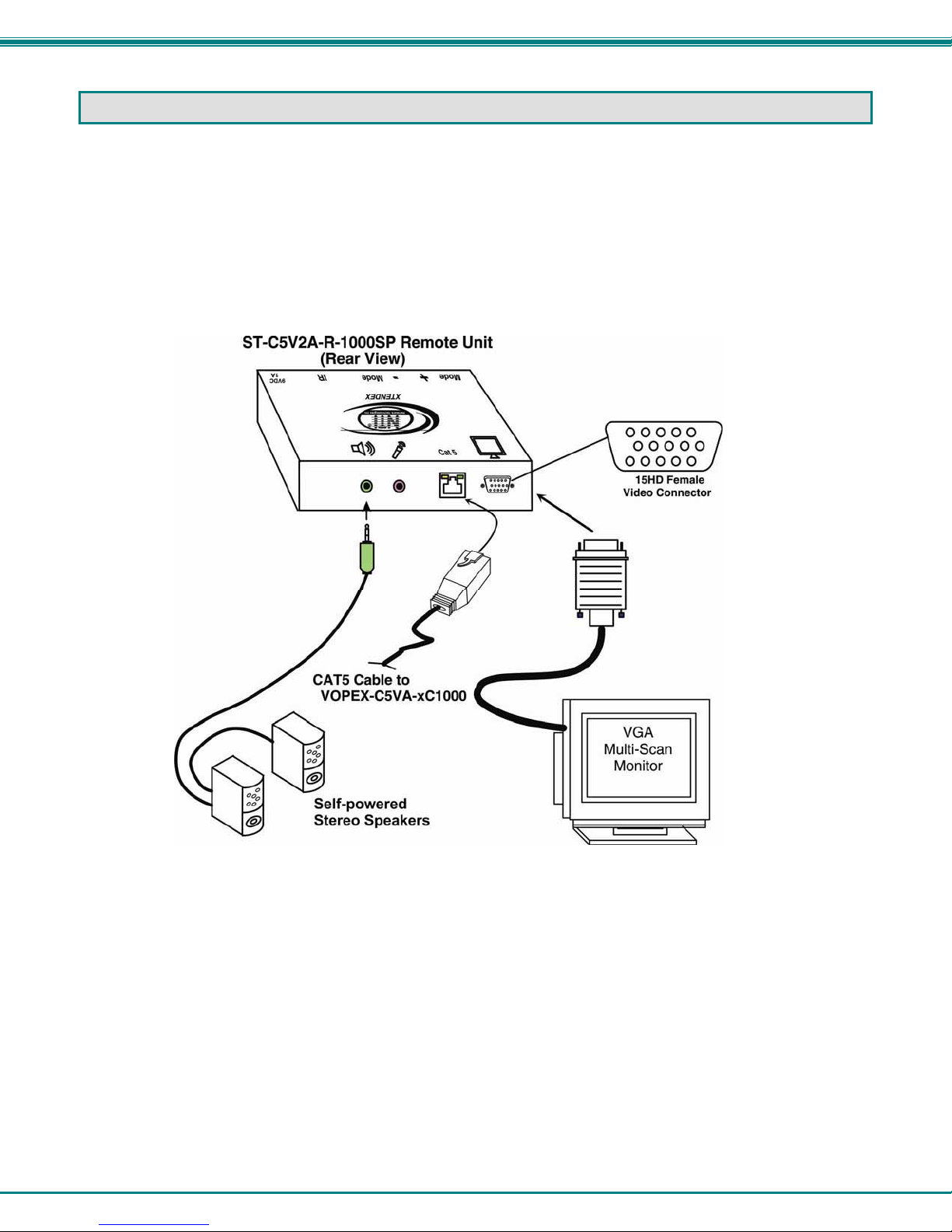
ST-C5V2A-R-1000SP and ST-C5V-R-1000SP Remote Unit......................................................................................6
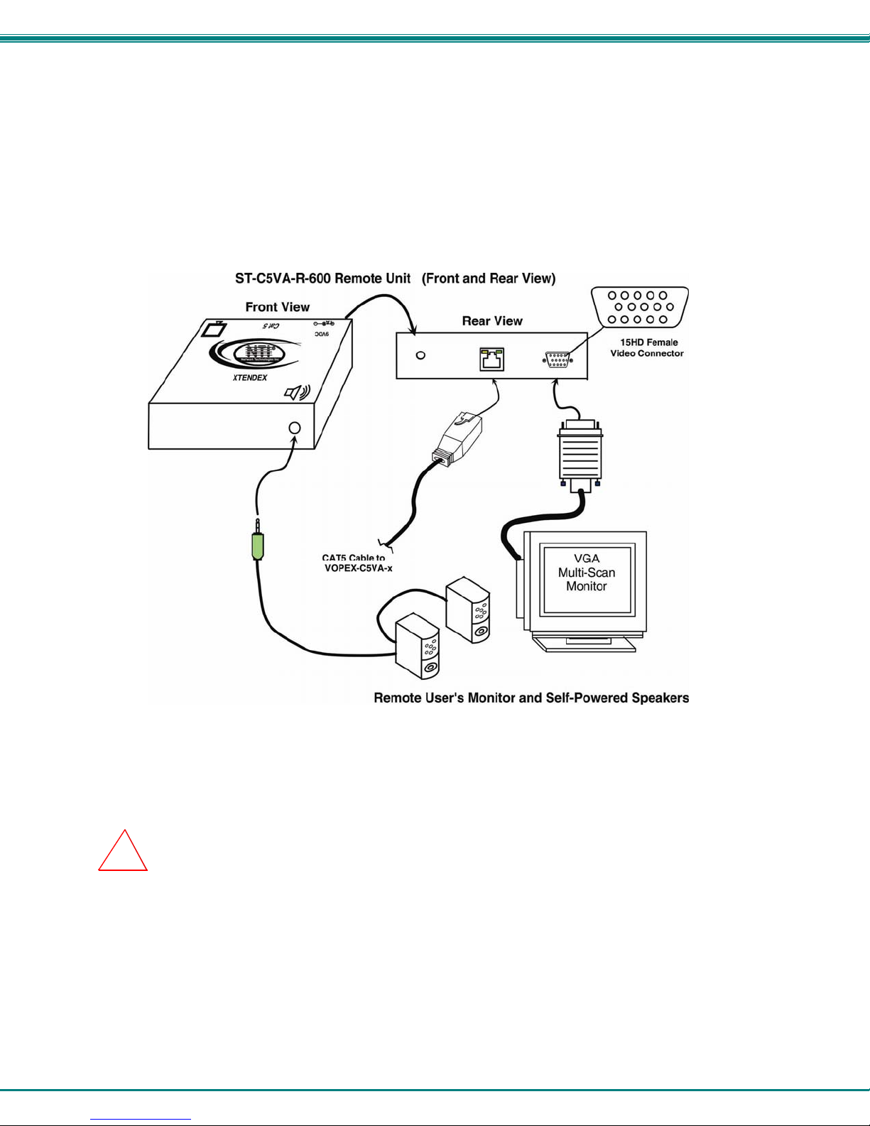
ST-C5VA-R-600 and ST-C5V-R-600 Remote Unit .....................................................................................................7
Connect the CAT5 cable..............................................................................................................................................8
Plug-in and Boot Up........................................................................................................................................................9
Video Quality Adjustment..............................................................................................................................................10
VOPEX-C5VA-xC1000..............................................................................................................................................10
More About DDC .................................................................................................................................................10
Fine Video Quality Adjustment..................................................................................................................................10
ST-C5V-R-1000 Video-Only Extenders..................................................................................................................10
Test Patterns for Color Skew Adjustment...............................................................................................................10
ST-C5V-R-600 Video-Only Extenders....................................................................................................................12
Technical Specifications................................................................................................................................................13
Interconnection Cable Wiring Method...........................................................................................................................14
RJ45 Connector Wiring..............................................................................................................................................14
Troubleshooting.............................................................................................................................................................15
Warranty Information.....................................................................................................................................................15
TABLE OF FIGURES
Figure 1- Connecting a VOPEX to a CPU..........................................................................................................................................4
Figure 2- Make connections to 1000 Foot XTENDEX Remote Unit...................................................................................................6
Figure 3- Make connections to 600 Foot XTENDEX Remote Unit.....................................................................................................7
Figure 4- Connect the CAT5 cable to the Remote Units....................................................................................................................8
Figure 5- Connect an AC adapter to a 1000 Foot Remote Unit.........................................................................................................9
Figure 6- DDC Update button for EDID data update........................................................................................................................10
Figure 7- Video Adjustment buttons.................................................................................................................................................11
Figure 8- Video quality adjustment buttons on XTENDEX Receiver................................................................................................12
Figure 9- View looking into RJ45 female..........................................................................................................................................14

NTI VOPEX SERIES SPLITTER/EXTENDER
1
INTRODUCTION
The VOPEX® Series Cat5 Video/Audio Splitter/Extender (VOPEX) is designed to enable one Video/Audio source to be
viewed and heard in 4 or 8 different remote locations. Remote video and audio devices can be located as much as 1000 feet
away from the source via Category 5 unshielded twisted-pair cable. The VOPEX-C5VA-xC1000 (x=4 or 8 port) also allows a
local video and audio device to be located near the source. Up to 4 or 8 receivers may be connected to the VOPEX.
Note: If the audio support is not present in the Remote Unit(s), please disregard all audio references.
The VOPEX will broadcast up-to-the-minute information to multiple remote monitors in real time. This high-resolution VGA
video splitter (video port expander) is the ideal solution for any application requiring the flexibility to share information with
several locations. Audio functionality using self-powered stereo speakers enhances your presentation.
The VOPEX Series Video/Audio Splitter/Extender is extremely simple to install and has been thoroughly tested to insure
reliable performance. Through the use of Category 5 unshielded twisted-pair cable it is possible to economically increase
the flexibility of a computer/home entertainment system. Here are some of the features and ways this can benefit the user:
•Allows the placement of monitors and self-powered stereo speakers/amplifiers in different remote locations
where only these parts are needed.
•Provides an additional local access port allowing the A/V source to viewed and heard locally.
•Provides crisp and clear resolution up to 2048x1536 using NTI's 1,000' remote units and 1920x1440 using NTI's
600' remote units.
•Video quality adjustment is automatic for varying lengths of CAT5 cable
•Digital transmission of audio signals reduces any loss in quality.
•Compatible with all NTI A/V switches and splitters, enabling the joining of products to create a
system that satisfies all networking needs.
MATERIALS
Materials Included with this kit:
¾VOPEX-C5VA-xC1000 (x=4 or 8 for number of CAT5 ports)
¾120VAC or 240VAC at 50 or 60Hz-5VDC/3A AC Adapter
¾Line cord, country specific
¾CD with a pdf file of this manual
¾VEXT-3 15HD male-female video cable for connecting the VOPEX to the video source
¾SA-3-MM 3.5mm stereo plug-stereo plug cable for connecting the VOPEX to the audio source
Additional materials not supplied but are required:
¾CAT5 unshielded twisted-pair cable(s) terminated with RJ45 connectors wired straight thru- pin 1 to pin 1, etc. (see pg.
14 for proper EIA/TIA 568B wiring method)
¾One or more of any of the following XTENDEX receivers:
Model Maximum CAT5 Cable (in Feet) Supported
ST-C5VA-R-600 600 Video + Audio
ST-C5V-R-600 600 Video Only
ST-C5VAX2-R-600 600 Dual Video + Audio
ST-C5VX2-R-600 600 Dual Video Only
ST-C5V2A-R-1000SP 1000 Video + Audio
ST-C5V-R-1000SP 1000 Video Only
Contact your nearest NTI distributor or NTI directly for all of your KVM needs at 800-RGB-TECH (800-742-8324) in US &
Canada or 330-562-7070 (Worldwide) or at our website at http://www.networktechinc.com and we will be happy to be of
assistance.

NTI VOPEX SERIES SPLITTER/EXTENDER
2
FEATURES AND FUNCTIONS
VOPEX
# LABEL CONNECTOR/LED DESCRIPTION
1 5V 3.0A 1.3x3.5mm Power Jack connection jack for 5VDC AC adapter
2 PWR Green LED illuminates when power has been supplied to the VOPEX
3 DDC Update Gray Button Press to transfer updated EDID data from remote units to CPU
4 Ground Crimp Terminals For attachment of earth ground to VOPEX
5 CATx Out 1-4 RJ45 for connecting CAT5 cables from XTENDEX Receivers
6 Video In 15HD Male for connecting the video source
7 Audio In 3.5mm female stereo audio for connecting the cable from the audio source
8 Video Out 15HD Female for connecting the local user’s monitor
9 Audio Out 3.5mm Female stereo audio for connecting the local user’s self-powered stereo speakers
XTENDEX
# LABEL CONNECTOR/LED DESCRIPTION
1 9V 1.0A 2.1x5.5mm Power Jack connection jack for 9VDC AC adapter
2 Audio Out green 3.5mm female stereo
audio for connecting the remote user’s self-powered stereo speakers
3 Microphone
pink 3.5mm female stereo
audio for connecting a microphone (feature not supported as of this printing)
4 CAT5 RJ45 for connecting CAT5 cable to VOPEX
4a --- Green LED for indicating power to the connector
4b --- Yellow LED for indicating data traffic between the VOPEX and XTENDEX
5 Monitor 15HD Female for connecting the remote user’s monitor
6 Mode Button for switching between skew and video quality adjustment
7 + / - Buttons for fine video quality adjustment
8 Mode Green and Red LED for visual indication of skew or video quality adjustment modes
9 IR IR Jack for connection of an Infrared Sensor for remote control (feature not
supported as of this printing)

NTI VOPEX SERIES SPLITTER/EXTENDER
3
LIMITATIONS
•The audio input of the VOPEX-C5VA-xC1000 is compatible with the following standard CPU audio outputs:
•Line out - typically lime green in color
•Speaker out- typically orange in color
•Headphone out
•The audio outputs of the VOPEX and the XTENDEX Receiver are compatible with self-powered stereo speakers.
PREPARATION FOR INSTALLATION
•Locations should be chosen for the monitors and speakers that also have space to connect the VOPEX and XTENDEX
Remote Units within the distance provided by the cables. If extension cables are needed, contact NTI for the cables
required.
•The CAT5 cables must be run to the locations where the VOPEX and XTENDEX Remote Units will be connected. Be
careful to route the cables away from any sources of magnetic fields or electrical interference that might reduce the
quality of the video signal (i.e. AC motors, welding equipment, etc.). NOTE: If CAT5 cable is already installed in the
wall and there are RJ45 wall outlets, it will be necessary to obtain male-to-male straight through connection cables long
enough to reach from the wall outlets to the connection locations of the VOPEX and XTENDEX Receivers.
•A properly grounded, polarized, and preferably surge-protected 120V or 240V electrical outlet (depending on the AC
adapter being used) must be installed close enough to the connection location of the VOPEX and XTENDEX Receivers,
monitors, stereo speakers, and CPU to plug them into.
•All cables should be installed in such a way that they do not cause stress on their connections to the equipment.
Extended lengths of cable hanging from a connection may interfere with the quality of that connection. Secure cables
as needed to minimize this.
•Properly shut down and disconnect the power from all devices to be separated. If other equipment is involved whose
connections are being interrupted, be sure to refer to the instruction manuals for that equipment for proper disconnection
and re-connection procedures before proceeding.
Note: CAT5 connection cable used between NTI VOPEX and XTENDEX Series Remote or any XTENDEX Series
products should not be run underground, outdoors or between buildings.
WARNING: Outdoor or underground runs of CAT5 cable could be dangerous and will void the warranty.
Up to 600 feet of CAT5 cable can be installed between the VOPEX and any ST-C5V(A)-R-600 or ST-C5V(A)X2-R-600
Remote Unit.
Up to 1000 feet of CAT5 cable can be installed between the VOPEX and any ST-C5V(2A)-R-1000SP Remote Unit.
Use the charts on page 13 to determine what length of cable can be used for the desired resolution.
!

NTI VOPEX SERIES SPLITTER/EXTENDER
4
VOPEX INSTALLATION
Any or all of the 4 models of Remote Units listed on page 1 can be connected to the VOPEX and any time. The features
that are usable will depend on the models that are connected. For example, the DDC Update button will be effective for any
1000 foot Remote Units that are connected, but may not work on the 600 foot Remote Units (depending upon the features
available at the time of manufacture).
VOPEX-C5VA-xC1000
1. Make connections between the VOPEX and the audio and video source(s). (See Fig. 1.)
a) Connect the male15HD cable end of a VEXT-3 to the VGA connector on the back of the
video source.
b) Connect the female 15HD cable end of the VEXT-3 cable to the 15HD male
connector marked "Video" on the VOPEX.
c) Connect one 3.5mm stereo plug end of the SA-3-MM cable into the 3.5mm female audio
connector marked "line out", "spkr", or "headphones" on the audio source.
Notes:
If all 3 connectors are available, use the connector marked "line out".
The "line out" connector is typically lime green and may be marked with this symbol
The "spkr" connector is typically orange, and may be marked with this symbol
The "headphones" connector may be marked with this symbol
d) Connect the other 3.5mm stereo plug end of the SA-3-MM cable into the 3.5mm female stereo
audio connector marked "Audio In" on the VOPEX.
Figure 1- Connecting a VOPEX to a CPU

NTI VOPEX SERIES SPLITTER/EXTENDER
5
2. Connect the local user to the VOPEX.
a) Connect the cable from the local user's VGA monitor to the 15HD female connector
marked "Monitor" on the VOPEX.
b) Connect the cable from the local speakers into the 3.5mm stereo audio connector marked "Audio
Out" on the VOPEX.
3. Connect a CAT5 cable to any one of the “Cat5x” ports on the VOPEX. When properly inserted the cable end
should snap into place.
4. Repeat step 3 for each Remote Unit to be connected to the VOPEX-C5VA-x.
Note: If an RJ45 wall outlet is being used, connect the other end of the extension cable to the
RJ45 wall outlet.
WARNING: Never connect the VOPEX Extender/Splitter to an Ethernet card, Ethernet router, hub or
switch or other Ethernet RJ45 connector of an Ethernet device. Damage to devices connected to the Ethernet
may result.
!

NTI VOPEX SERIES SPLITTER/EXTENDER
6
REMOTE UNIT INSTALLATION
ST-C5V2A-R-1000SP and ST-C5V-R-1000SP Remote Unit
1. Position the Remote Unit such that the CAT5 cable, the monitor cable, device cables, and the AC
adapter power connector can each reach the Remote Unit without putting strain on the cables.
2. Connect the monitor cable to the female 15HD video connector on the Remote Unit.
3. If the Remote Unit has audio support, connect the cable from the remote speakers to the 3.5mm
stereo audio jack with the speaker symbol on the Remote Unit. (See Fig. 7)
Figure 2- Make connections to 1000 Foot XTENDEX Remote Unit
4. Connect CAT5 cable as described on page 8.

NTI VOPEX SERIES SPLITTER/EXTENDER
7
ST-C5VA-R-600 and ST-C5V-R-600 Remote Unit
Note: This section is applicable to both models of Remote Unit except for step 3. When installing ST-C5V-R-600
Remote Units (no audio support), disregard step 3.
1. Position a ST-C5VA-R-600 Remote Unit such that the CAT5 cable, the monitor cable, speaker cable,
and the AC adapter power connector can each reach the Remote Unit comfortably.
2. Connect the remote user's monitor cable to the female 15HD video connector on the Remote Unit.
3. Connect the remote user's speakers to the 3.5mm female stereo connector on the Remote Unit (see
Fig. 3).
Figure 3- Make connections to 600 Foot XTENDEX Remote Unit
Note: If an RJ45 wall outlet is being used, connect the other end of the extension cable to the RJ45
wall outlet.
WARNING: Never connect the ST-C5VA-R-600 Remote Unit to an Ethernet card, Ethernet router, hub or
switch or other Ethernet RJ45 connector of an Ethernet device. Damage to devices connected to the Ethernet
may result.
4. Repeat steps 1-3 for each ST-C5VA-R-600 Remote Unit to be connected to the VOPEX.
5. Connect CAT5 cable as described on page 8.
!

NTI VOPEX SERIES SPLITTER/EXTENDER
8
Connect the CAT5 cable
Make sure the CAT5 cable has been installed in accordance with the
“Preparation for Installation” instructions on page 3. Connect the CAT5 cable to
the “Cat 5” port on each Remote Unit. (See Fig. 4) When properly inserted the
CAT5 cable end should snap into place.
Note: If an RJ45 wall outlet is being used, connect the other end of the
extension cable to the RJ45 wall outlet.
WARNING: Never connect the XTENDEX to an Ethernet card,
Ethernet router, hub or switch or other Ethernet RJ45 connector of an
Ethernet device. Damage to devices connected to the Ethernet may
result.
Figure 4- Connect the CAT5 cable to the Remote Units
Up to 600 feet of CAT5 cable can be installed between the VOPEX and any ST-C5V(A)-R-600 Remote Unit.
Up to 1000 feet of CAT5 cable can be installed between the VOPEX and any ST-C5V(2A)-R-1000SP Remote Unit.
Use the charts on page 13 to determine what length of cable can be used for the desired resolution.
!

NTI VOPEX SERIES SPLITTER/EXTENDER
9
PLUG-IN AND BOOT UP
1. Plug the power cord from each video device and the power supply for each audio device into a power outlet.
2. Connect the 5VDC 3A power connector to the power port on the VOPEX (shown in Fig. 1- Page 5).
3. Connect a 9VDC 1A AC adapter to each XTENDEX Remote Unit. Make sure the power connectors go into each port
all the way.
4. Plug each AC adapter into a power outlet. The green LEDs on the VOPEX and the RJ45 connector of each XTENDEX
Receiver should illuminate, indicating that a proper power connection has been made to them. (See Fig. 5)
Figure 5- Connect an AC adapter to a 1000 Foot Remote Unit
5. Turn ON the audio and video source(s), stereo speakers, and monitors. They should react as if they were
directly connected to each other.
Note: The yellow LED on the RJ45 connector of each XTENDEX Receiver will blink anytime data traffic is passing
between the VOPEX and the XTENDEX Receivers, indicating proper CAT5 cable connection and communication.
(See Fig. 5)

NTI VOPEX SERIES SPLITTER/EXTENDER
10
VIDEO QUALITY ADJUSTMENT
VOPEX-C5VA-xC1000
When powering ON the VOPEX-C5VA-xC1000, video quality adjustment is done automatically to assure the image is as
clear as possible. Once the VOPEX is up and running, an adjustment may need to be made to the resolution setting of the
CPU, due to variations in compatible resolutions in the monitors connected to the Remote Units. To make sure the CPU has
updated EDID data to choose from, press the “DDC Update" button. (See Fig. 6). The VOPEX will compare EDID tables
from each monitor connected to a 1000 Series Remote Unit and supply the compatible resolutions to the CPU as available
options. Once that has been done, select the desired resolution from the available settings in your operating system.
Note: The 600 Series extenders do not support the DDC Update feature as of this printing.
Figure 6- DDC Update button for EDID data update
More About DDC
The recording and DDC transfer of EDID data from the monitor(s) enables the CPU to know what resolution settings are
compatible with the monitor(s) connected. Once this data is provided to the CPU, your graphics card will either
automatically update to the best resolution available (some models of graphic cards, not all), or you will need to choose from
the available settings. Bear in mind, the choices of settings compatible with the monitors are not necessarily all going to be
usable. If the length of CATx cable in your installation is too long for the selected resolution, the image at the Remote Unit
monitor may not be viewable. Be sure to select a resolution setting that your installation will support. For supported
combinations, see the chart on page 13.
Video quality may need to be re-adjusted if any of the following situations occur:
•A CAT5 cable is replaced, for any reason
•A new XTENDEX Remote unit is connected to the system
•CAT5 cable becomes disconnected from the VOPEX or any of the Remote Units
Note: When the cable is longer than 300 feet some colored lines can be seen at the black-to-white transitions. This
is a normal behavior and is caused by the different twisting rates of each pair of wires in the CAT5 cable.
Fine Video Quality Adjustment
ST-C5V(A)-R-1000 Video-Only Extenders
It is possible that on initial startup the image on the monitor will not be as crisp as the image normally is or the colors may
not appear as they normally would. The colors may also be skewed, or out of alignment as they appear on the monitor.
This is due to the frequency characteristics of the CAT5 cable and differences in cable types that can be used (i.e. shielded
vs. unshielded cable and CAT5 vs. CAT6 cable). Models without keyboard support include a “Mode” button for the
following functions:
¾fine adjustment of the general video quality
¾fine adjustment of color skew (alignment of red, green, and blue signals on the monitor)
¾update DDC information between the monitor(s) and CPU
Test Patterns for Color Skew Adjustment
To verify the need for and effect of color skew adjustment using a test pattern specifically designed for
your display setting, browse the CD this manual was found on and click on the “test-pattern-nXm.pdf”
file that matches your current video resolution. Follow the instructions below to make adjustments as
needed.

NTI VOPEX SERIES SPLITTER/EXTENDER
11
Depending upon what mode the XTENDEX is in, the “+” (plus)
and “-“ (minus) buttons can be pressed to make the adjustment.
A “Mode” LED is provided to indicate what characteristic is being
changed.
Figure 7- Video Adjustment buttons
Note: The VOPEX and Remote Units must be connected and communicating in order for the mode button to
function.
The chart below describes the video quality changes that can be made with the Mode button and the associated indication
provided by the Mode LED.
Mode Button
Action LED Indication Press + or – to effect:
At power ON Dark (LED OFF) General Video Quality
First Press Red Red Skew
Second Press Green Green Skew
Third Press Orange Blue Skew
Fourth Press Green Flashing -
slow DDC remote update
(press + or – to update
DDC from remote
monitor)
Fifth Press Green Flashing -
rapid DDC local update
(press + or – to update
DDC from locally
connected monitor)
Sixth Press
(Not useful to this
product.
Microphone
not supported)
Red Flashing-
rapid or slow Active microphone
Flash rapid= remote
Flash slow= local
(press + or – to toggle
which is active)
Seventh Press Dark (LED OFF)- repeat cycle
When adjusting color skew, a momentary press of either the “+” (plus) or “-“ (minus) buttons button will make a minor change
in the image. If either button is pressed and held, the changes made will be gradual and continuous. Ultimately, the image
quality should improve to a satisfactory level. Once the adjustment is made, it should not be necessary to change it again,
as the new settings are stored in memory and become the default settings with each startup.
If the image still lacks definition, configuration adjustments may need to be made to the attached video display equipment.
This is a problem most often seen in LCD displays. Check the manual for the equipment having the poor display and look
for an "auto-adjust" or "auto-configure" feature. Once this is done, you may need to repeat the Video Adjustment
procedure described above to achieve the best image.
Note: After pressing the Mode button,
if there is a pause in button activity
for 30 seconds or more, the feature
will return to a power-ON state with
the LED OFF.

NTI VOPEX SERIES SPLITTER/EXTENDER
12
ST-C5V(X2)-R-600 Video-Only Extenders
Video quality adjustment of the monitor connected to an ST-C5V-R-600 Remote Unit or ST-C5VX2-R-600 is performed
manually at the Remote Unit.
It is possible that on initial startup the image on the monitor will not be as crisp as the image normally is. This is due to the
frequency characteristics of the CAT5 cable. It may be necessary to press the "+" or "-" buttons on the Remote Unit (see
Fig. 8) until the image is crisp and clear. Press the "+" button if the image is not crisp and clear enough. Press the "-"
button if the image has been over-corrected (such that horizontal lines appear to trail or shadow at the edge of an open
window). A momentary press of either button will make a minor change in the image. If either button is pressed and held,
the changes made will be gradual and continuous. Ultimately, the image quality should improve to a satisfactory level.
Once the adjustment is made, it should not be necessary to change it again as the new settings are stored in memory and
become the default settings with each startup.
Note: When the cable is longer than 300 feet some colored lines can be seen at the black-to-white transitions. This
is a normal behavior and is caused by the different twisting rates of each pair of wires in the CAT5 cable.
Figure 8- Video quality adjustment buttons on XTENDEX Receiver

NTI VOPEX SERIES SPLITTER/EXTENDER
13
TECHNICAL SPECIFICATIONS
Characteristic With 600 Foot XTENDEX Remote Units
Connected With 1000 Foot XTENDEX Remote
Units Connected
Video Compatibility SVGA, XGA, VGA VGA,SVGA, XGA, SXGA,UXGA
Video Quality Adjustment
Automatic, for up to 600 feet of CAT5
cable, with manual override
(fine video quality adjustment can only be
performed manually at the Remote Unit
for ST-C5V-R-600)
Automatic, for up to 1000 feet of CAT5
cable, with manual override
(fine video quality adjustment can only be
performed manually at the Remote Unit)
Sync Types Supported Separate and composite TTL Level and
sync on green Separate and composite TTL Level
General (All Models)
Maximum Resolution See charts below and on next page
Video Connectors HD15 male to CPU
HD15 female to monitor
Video Coupling DC
Video Maximum I/O Levels 1.45Vp-p
Input / Output Impedance 75 Ohms
Input Horizontal Frequency Range 15kHz to 130 kHz
Input Vertical Frequency Range 30 Hz to 150 Hz
Audio Connectors 3.5mm female stereo audio connectors
Signal Type Line Level, stereo, unbalanced
Audio Frequency Response 20Hz to 20Khz, + 1dB
Signal-to-noise ratio >76 dBA
Total Harmonic Distortion and Noise 0.017%,F=20-20KHz, RL=2K Ohm, Vout=1 Vrms
Stereo Crosstalk -70 dB @ 1kHz
Audio Maximum I/O Levels 3.1Vp-p
Output Impedance Max 2K Ohms, unbalanced
Interconnect Cable CAT5/5e Solid UTP EIA/TIA 568B wiring w/ male RJ45 connectors
VOPEX-C5V(A)-4/8C1000 Power 120V or 240V at 50 or 60Hz-5VDC/3A via AC Adapter
Remote Unit Power 120V or 240V at 50 or 60Hz-9VDC/1.0A via AC Adapter
AC Adapter Power Connector- VOPEX 1.3X3.5mm connector, center positive
AC Adapter Power Connector- Remote Units 2.1 x 5mm connector, center positive
Operating Temperature Range 32°F to 100°F (0°C to 38°C)
VOPEX Size (In.) WxDxH
VOPEX-C5VA-4C1000
VOPEX-C5VA-8C1000
5.13x3.45x1.08
5.13x3.45x1.68
XTENDEX Remote Unit Size (In.) WxDxH
600 Foot Series
1000 Foot Series
3.25x3.4x1
5.05x3.1x1.235
ST-C5V(2A)-R-1000SP Remote Units
Distances and Maximum Supported Resolutions for CAT5, CAT5e and CAT6 Cables
Unshielded Twisted Pair (UTP) Resolutions Shielded Twisted Pair (STP) Resolutions
UTP CABLE DISTANCE (feet) RESOLUTION STP CABLE DISTANCE (feet) RESOLUTION
CAT5/5e 1000 1920x1200 at 60Hz CAT5/5e 800** 1920x1200 at 60Hz
CAT5/5e/6 800* 1920x1440 at 60Hz CAT5/5e 600 1920x1440 at 60Hz
CAT5/5e/6 600 2048x1536 at 60Hz CAT5/5e 400 2048x1536 at 60Hz
CAT6 400** 1280x1024 at 60Hz
CAT6 300 1600x1200 at 60Hz
CAT6 200 2048x1536 at 60Hz
*The performance of CAT6 unshielded, is not guaranteed
beyond 800 feet.
**The performance of CAT5 and CAT5e shielded cable is not
guaranteed beyond 800 feet (400 feet for CAT6 shielded).

NTI VOPEX SERIES SPLITTER/EXTENDER
14
ST-C5VA-R-600 Remote Units
Distances and Maximum Supported Resolutions for CAT5, CAT5e and CAT6 Cables
CABLE DISTANCE (feet) RESOLUTION
CAT5/CAT5e (UTP) 600 1024x768 at 60Hz
CAT5/CAT5e (UTP) 400 1280x1024 at 60Hz
CAT5/CAT5e (UTP) 300 1600x1200 at 60Hz
CAT5/CAT5e (UTP) 100 1920x1440 at 60Hz
CAT6 (UTP) 300 1024x768 at 60Hz
CAT6 (UTP) 200 1280x1024 at 60Hz
CAT6 (UTP) 100 1920x1440 at 60Hz
INTERCONNECTION CABLE WIRING METHOD
The connection cable between the VOPEX and each XTENDEX Receiver is terminated with either RJ45 connectors or M12
connectors (see installation instruction for you model) and must be wired according to the EIA/TIA 568B industry standard.
Wiring is as per the tables and drawings below.
RJ45 Connector Wiring
Pin Wire Color Pair Function
1 White/Orange 2 T
2 Orange 2 R
3 White/Green 3 T
4 Blue 1 R
5 White/Blue 1 T
6 Green 3 R
7 White/Brown 4 T
8 Brown 4 R
Figure 9- View looking into RJ45 female
Note: CAT5 connection cable used between NTI XTENDEX Series Local and Remote or any XTENDEX Series
products should not be run underground, outdoors or between buildings.
WARNING: Outdoor or underground runs of CAT5 cable could be dangerous and will void the warranty.
T
1
+
R
2
-
T
3
+
R
4
-
T
5
+
R
6
-
T
7
+
R
8
-
Pair 2 Pair 1 Pair 4
Pair 3
!

NTI VOPEX SERIES SPLITTER/EXTENDER
15
TROUBLESHOOTING
Each and every piece of every product produced by Network Technologies Inc is 100% tested to exacting specifications.
We make every effort to insure trouble-free installation and operation of our products. If problems are experienced while
installing this product, please look over the troubleshooting chart below to see if perhaps we can answer any questions that
arise. If the answer is not found in the chart, a solution may be found in the knowledgebase on our website at
http://information.networktechinc.com/jive/kbindex.jspa or please call us directly at (800) 742-8324 (800-RGB-TECH) or
(330) 562-7070 and we will be happy to assist in any way we can.
Problem Cause Solution
VOPEX or XTENDEX
power LED does not
illuminate
•Power supply is not connected or
plugged-in.
•Make sure each outlet is live and the AC adapters are
plugged-in. (one for each Remote and one for the
VOPEX)
•Make sure DC plugs are fully connected
No video on
monitor/display
•One or more video cables is loose
or disconnected.
•No power to the VOPEX or the
XTENDEX Receiver.
•Video Cable was not attached
when CPU was booted.
•CAT5 cable is not connected.
•Check all video cable connections
•Make sure power LEDs are illuminated for local and
remote. If not, see solution for problem above.
•With all the cables properly connected, reboot the CPU.
•Check cable connections. Make sure they are snapped-
in properly and completely and reboot.
The picture on the monitor
is black and white, rather
than color
The video cable was not attached to
the CPU when it was booted. With the cables all properly connected, reboot the CPU.
Monitor sometimes loses
sync, causing it to go
blank for a second or two
•Electrical power system is very
noisy, particularly the ground.
•The CAT5 cable is not properly
connected.
•Make sure the interconnection cable is not near any
power lines.
•Check cable connections. Make sure they are snapped-
in properly and completely.
A constant vertical wobble
appears down the screen •CAT5 cable is too close to a
strong power source.
•Monitor is too close to a power
source or another monitor.
•Reroute CAT5 cable if possible.
•Move the monitor
Video picture is not sharp
or is smeared •All Video Cables are not firmly
seated.
•CAT5 cable is too long.
•Video was not manually adjusted
•Check all connections. Make sure all cables are fully
seated.
•Verify length is within specified limits.
•Adjust video quality at the receiver (See "Video Quality
Adjustment" on page 11.)
No audio •Audio cable is not properly
plugged in
•Speakers are not plugged in
•Check all cable connections
•Verify speakers are powered (if applicable)
WARRANTY INFORMATION
The warranty period on this product (parts and labor) is two (2) years from the date of purchase. Please contact Network
Technologies Inc at (800) 742-8324 (800-RGB-TECH) or (330) 562-7070 or visit our website at
http://www.networktechinc.com for information regarding repairs and/or returns. A return authorization number is required
for all repairs/returns.
Manual 186 Rev. 12/13/12
This manual suits for next models
2
Table of contents
Other NTI Cables And Connectors manuals

NTI
NTI VOPEX-HDS-x User manual

NTI
NTI HD4K18GB-FO MM Series User manual

NTI
NTI SPLITMUX Series User manual

NTI
NTI VOPEX-C5VA/C5V-x(C) User manual

NTI
NTI USB-AA-5M User manual

NTI
NTI XTENDEX Series User manual

NTI
NTI HD4K18GB-FO-xx-MM User manual

NTI
NTI VOPEX Series User manual

NTI
NTI Vopex-2V User manual

NTI
NTI VOPEX Series User manual