NTI XTENDEX ST-C6HD-HDBT-LC User manual

MAN152 Rev Date 6/22/2012
ST-C6HD-HDBT-LC
328 FOOT HDMI, Digital Audio and IR
Extender
Installation and Operation Manual
XTENDEX®Series
ST-C6H
D
-HDBT-
L
C
R
emote and
L
ocal Unit

i
TRADEMARK
XTENDEX is a registered trademark of Network Technologies Inc in the U.S. and other countries.
COPYRIGHT
Copyright © 2008,2012 by Network Technologies Inc. All rights reserved. No part of this publication may be reproduced, stored
in a retrieval system, or transmitted, in any form or by any means, electronic, mechanical, photocopying, recording, or otherwise,
without the prior written consent of Network Technologies Inc, 1275 Danner Drive, Aurora, Ohio 44202.
CHANGES
The material in this guide is for information only and is subject to change without notice. Network Technologies Inc reserves the
right to make changes in the product design without reservation and without notification to its users.
Note: CATx connection cable used between NTI XTENDEX Series Local and Remote or any XTENDEX Series products
should not be run underground, outdoors or between buildings.
WARNING: Outdoor or underground runs of CATx cable could be dangerous and will void the warranty.

ii
TABLE OF CONTENTS
Introduction......................................................................................................................................................................1
Materials..........................................................................................................................................................................2
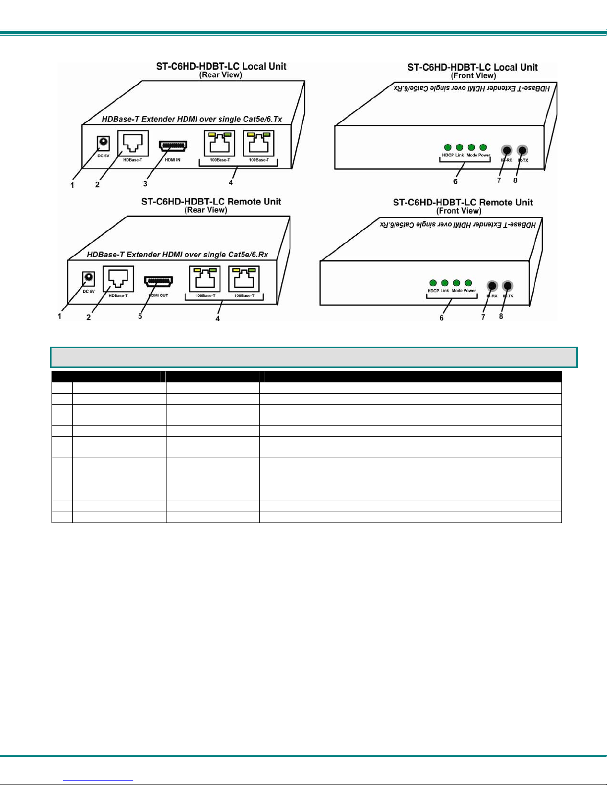
Connectors and LEDs.....................................................................................................................................................3
Limitations .......................................................................................................................................................................4
Preparation for Installation ..............................................................................................................................................4
Installation .......................................................................................................................................................................5
Installing The Local Unit ..............................................................................................................................................5
Installing The Remote Unit ..........................................................................................................................................5
Connect the CATx Cables...........................................................................................................................................6
Plug-in and Boot Up.....................................................................................................................................................6
Infrared Control ...............................................................................................................................................................7
Technical Specifications..................................................................................................................................................8
Interconnection Cable Wiring Method.............................................................................................................................8
Troubleshooting...............................................................................................................................................................9
Warranty Information.......................................................................................................................................................9
TABLE OF FIGURES
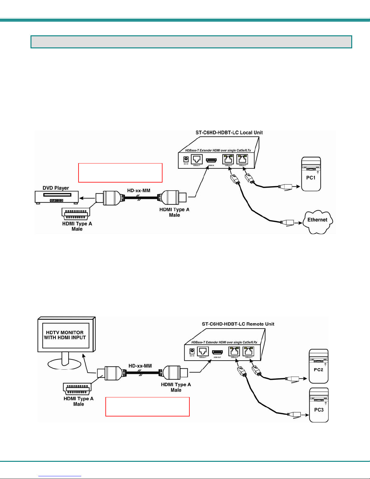
Figure 1- Install the Local Unit to the source......................................................................................................................................5
Figure 2- Connect the extended components to the Remote Unit.....................................................................................................5
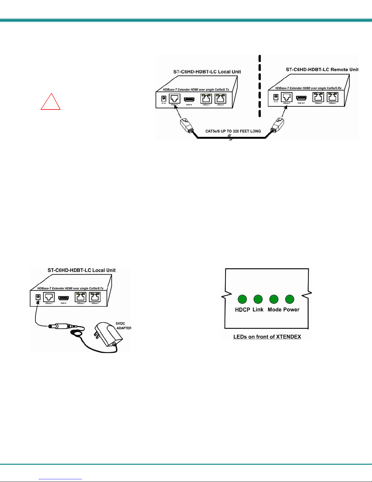
Figure 3- Connect CATx cable...........................................................................................................................................................6
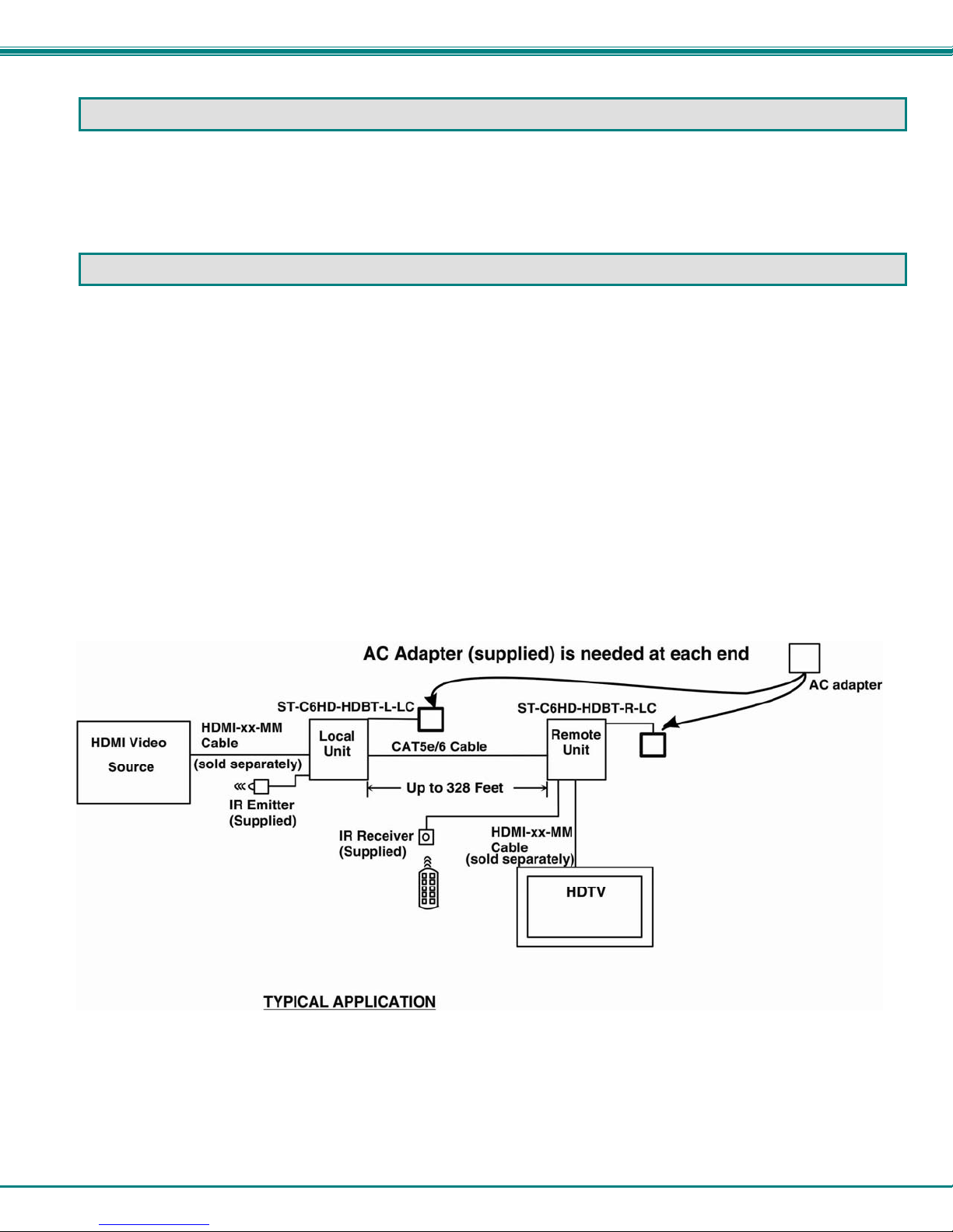
Figure 4- Connect the AC adapters to the Remote Unit and the Local Unit.......................................................................................6
Figure 5- Connect IR Emitter and Receiver.......................................................................................................................................7
Figure 6- View looking into RJ45 female............................................................................................................................................8

NTI XTENDEX 328 Foot HDMI and IR Extender
1
INTRODUCTION
The XTENDEX Series ST-C6HD-HDBT-LC HDMI HDBase-T Extender transmits uncompressed digital HDMI signal, IR, and
Ethernet up to 328 feet over a single CAT5e/6 cable using HDBase-T technology. Each video extender consists of a local unit that
connects to an HDMI source and a remote unit that connects to an HDMI display. The IR transport channel can be forward or
backward per your installation.
The XTENDEX Series Extender is extremely simple to install and has been thoroughly tested to insure reliable performance.
Through the use of CAT5e/6 (CATx) cable it is possible to economically increase the flexibility of an entertainment system. Here
are some of the features and ways this can benefit you:
•Transmits an uncompressed high speed HDMI signal over one CAT5e/6 cable.
•Supports HDTV resolutions to 1080p and computer resolutions to 1920x1200.
•HDMI features supported:
o36-bit Deep Color
ox.v.Color
oDolby TrueHD, DTS-HD Master Audio, Dolby Digital, DTS 7.1 and LPCM
oBandwidth up to 3.4 GHz
o3D
oSupport for CEC (consumer electronic control) compatible devices.
oLip Sync
•HDCP compliant.
•Supports the DDC2B protocol.
•High quality, rugged steel construction with durable powder coat finish.
•Full Infrared Remote (IR) control of HDMI source from remote HDTV using existing source remote control.
•IR transport can be forward or backward per installation.

NTI XTENDEX 328 Foot HDMI and IR Extender
2
MATERIALS
Materials Included with ST-C6HD-HDBT-LC kit:
9NTI XTENDEX Local Unit
9NTI XTENDEX Remote Unit
92-100VAC to 240VAC at 50 or 60Hz-5VDC/0.5A AC Adapter
93 Foot IR-EMITTER
93 Foot IR-RECEIVER
9This manual
Additional materials are required but are not supplied:
¾CAT5e solid UTP ; CAT6 solid UTP twisted-pair cables terminated with RJ45 connectors wired straight thru- pin 1 to pin 1,
etc. (see page 8 for proper EIA/TIA 568 B wiring method)
¾HDMI male-male cable to connect a HDMI source or display (Order NTI # HD-xx-MM where xx=3, 6, 9,14 foot cable).
(Maximum length supported is 15 feet)
Always use the shortest possible cable for best performance.
Contact your nearest NTI distributor or NTI directly for all of your KVM needs at 800-RGB-TECH (800-742-8324) in US & Canada
or 330-562-7070 (Worldwide) or at our website at http://www.networktechinc.com and we will be happy to be of assistance.

NTI XTENDEX 328 Foot HDMI and IR Extender
3
CONNECTORS AND LEDS
# LABEL CONNECTOR DESCRIPTION
1 DC 5V Power Jack connection jack for the AC adapter
2 HDBase-T RJ45 Connector Connector for CAT5e/6 cable between Local and Remote Units
3 HDMI In HDMI female video
connector for connecting an HDMI cable between the Local Unit and the video
source
4 100Base-T RJ45 Connectors For connecting devices or connection to LAN/Internet
5 HDMI Out HDMI female video
connector for connecting the remote display device
6 HDCP
Link
Mode
Power
Green LEDs Indicates HDCP data passing between video source and display
Indicates connection between Local and Remote Unit
Indicates normal operation when flashing
Indicates power has been supplied
7 IR-RX 3.5mm Stereo Jack for connecting the IR Receiver
8 IR-TX 3.5mm Stereo Jack for connecting the IR Transmitter

NTI XTENDEX 328 Foot HDMI and IR Extender
4
LIMITATIONS
•The use of CAT5 or of any stranded cabling will reduce the maximum distance and resolution.
PREPARATION FOR INSTALLATION
•Locations should be chosen for the monitor that also has space to connect the Remote unit within the distance provided by
the cables. If extension cables are needed, contact NTI for the cables required.
•The CATx cables must be run to the locations where the Remote and Local units will be connected. Be careful to route the
cables away from any sources of magnetic fields or electrical interference that might reduce the quality of the video signal
(i.e. AC motors, welding equipment, fluorescent lighting, etc.).
•All cables should be installed in such a way that they do not cause stress on their connections to the equipment. Extended
lengths of cable hanging from a connection may interfere with the quality of that connection. Secure cables as needed to
minimize this.
•Properly shut down and disconnect the power from the video source and monitor to be separated. If other equipment is
involved whose connections are being interrupted, be sure to refer to the instruction manuals for that equipment for proper
disconnection and reconnection procedures before proceeding.
•Be very careful not to obstruct the air vents on each unit in its installed location.

NTI XTENDEX 328 Foot HDMI and IR Extender
5
INSTALLATION
Installing The Local Unit
1. Connect an HD-x-MM (sold separately) or DVI-HD-xx-MM cable (page 2) between the HDMI signal source and the "HDMI In"
connector on the Local Unit.
2. Connect PC(s) or Ethernet connection from LAN to “100Base-T” ports as desired.
Note: Ethernet connection can be made either at the Local Unit or at the Remote Unit ports. Each PC connected to the
ST-C6HD-HDBT-LC will connect to the LAN through this Ethernet connection.
Figure 1- Install the Local Unit to the source
Installing The Remote Unit
1. Connect a HD-xx-MM to the female HDMI video connector labeled "HDMI Out" on the Remote Unit.
2. Connect PC(s) or Ethernet connection from LAN to “100Base-T” ports as desired.
Note: Ethernet connection can be made either at the Local Unit or at the Remote Unit ports. Each PC connected to the
ST-C6HD-HDBT-LC will connect to the LAN through this Ethernet connection.
Figure 2- Connect the extended components to the Remote Unit
The maximum HDMI cable
length supported is 15 feet
The maximum HDMI cable
length supported is 15 feet

NTI XTENDEX 328 Foot HDMI and IR Extender
6
Connect the CATx Cables
Connect the CATx cable between the
“HDBase-T” ports on the Local and Remote
Unit. (See Figure 3) When properly inserted
the cable ends should snap into place.
WARNING: Never connect the
“HDBase-T” port of this XTENDEX to an
Ethernet card, Ethernet router, hub or
switch or other Ethernet RJ45 connector
of an Ethernet device. Damage to
devices connected to the Ethernet may
result.
Figure 3- Connect CATx cable
Plug-in and Boot Up
1. Plug the power cord from the display into the power outlet.
2. Connect an AC adapter power connectors to the “DC 5V” ports on the Remote Unit and Local Units. Plug the AC adapters
into power outlets. The green “Power” LED on each unit should illuminate, indicating that a proper power connection has
been made to them. (See Figure 4)
3. Turn ON the video source and display. The “Link” LED on both the Local and Remote Units should illuminate. The video
source and monitor should each react as if directly connected to each other. If both are HDCP compliant, then the ‘HDCP”
LED on each unit should illuminate.
Note: If the video source is HDCP compliant and the display is not HDCP compliant, no image will be seen on the
display.
Figure 4- Connect the AC adapters to the Remote Unit and the Local Unit
!

NTI XTENDEX 328 Foot HDMI and IR Extender
7
INFRARED CONTROL
The XTENDEX includes ports for connecting an infrared emitter and receiver (included) to work in conjunction with the IR remote
control used to operate the signal source. Connect the receiver to the “IR RX” port on one end of the installation (Remote Unit
or Local Unit) and the emitter to the “IR TX” port on the other end. The IR transport channel can be forward or backward.
Position the end of the receiver such that the signal from the remote control can easily reach the IR sensor. Position the end of
the emitter such that the extended signal can be sent to the signal source.
Figure 5- Connect IR Emitter and Receiver
Note: The IR emitter or IR receiver (not both) can be connected at either end.
Note: The IR Emitter and Receiver work within a frequency range of 30-40kHz. Check the
specifications for the device you are extending to make sure the XTENDEX will work with it.

NTI XTENDEX 328 Foot HDMI and IR Extender
8
TECHNICAL SPECIFICATIONS
Video
Video Compatibility 1920x1200 resolutions/ HDTV resolution up to 1080p @60Hz
Video Connectors HDMI Type A Female
Input Video Signal 5.0 Volts P-P
Video Color Format 36bit Deep color
HDMI Version HDMI 1.4a
DDC Support DDC2b
HDCP Version HDCP 1.2
Audio
Audio Format LPCM,Dolby Digital (AC3)(Plus),DTS 7.1,DSD, Dolby TrueHD,DTS-HD Master Audio
IR
Input/Output 3.5mm Stereo Jack
Signal Type TTL, 0-5VDC
Input Impedance 1.5 kohm
Output Impedance 33 ohm
Maximum Input/Output Level 5.2 Vp-p
Center Carrier Frequency 36kHz
Frequency Range 30-40kHz
General
Interconnect Cable CAT5e solid UTP; CAT6 Solid UTP; EIA/TIA 568 B wiring with male RJ45 connectors
CATx Cable Range 328 ft maximum
Operating Temperature 5-131° F (-15-55° C)
Operating Humidity Range 5 to 90% non-condensing RH
Remote and Local Unit Power 100V to 240VAC at 50 or 60Hz-5VDC/0.5A via AC Adapter
Enclosure type Electro-galvanized steel black powder coated
Size (In.) WxDxH 4.37x2.95x.93
Compliance Certifications CE, RoHS
INTERCONNECTION CABLE WIRING METHOD
The CATx connection cables between the Remote and Local are terminated with RJ45 connectors and must be wired according
to the EIA/TIA 568 B industry standard. Wiring is per the table and drawing below.
Pin Wire Color Pair Function
1 White/Orange 2 T
2 Orange 2 R
3 White/Green 3 T
4 Blue 1 R
5 White/Blue 1 T
6 Green 3 R
7 White/Brown 4 T
8 Brown 4 R
Figure 6- View looking into RJ45 female
T
1
+
R
2
-
T
3
+
R
4
-
T
5
+
R
6
-
T
7
+
R
8
-
Pair 2 Pair 1 Pair 4
Pair 3

NTI XTENDEX 328 Foot HDMI and IR Extender
9
TROUBLESHOOTING
Each and every piece of every product produced by Network Technologies Inc is 100% tested to exacting specifications. We
make every effort to insure trouble-free installation and operation of our products. If problems are experienced while installing this
product, please look over the troubleshooting chart below to see if perhaps we can answer any questions that arise. If the
answer is not found in the chart, a solution may be found in the knowledgebase on our website at
http://information.networktechinc.com/jive/kbindex.jspa or please call us directly at (800) 742-8324 (800-RGB-TECH) or (330)
562-7070 and we will be happy to assist in any way we can.
Problem Cause Solution
Power LED does not
illuminate •Power supply is not connected or
plugged-in. •Make sure outlet is live and AC adapter is plugged-in.
•Make sure 5VDC jack is fully connected
No Video on display •One or more video cables is loose
or disconnected.
•No power to Remote Unit.
•CATx cable is not connected.
•CATx cable is too long
•HDMI cable is too long
•Display is not HDCP compliant but
HDMI source is
•Check all video cable connections
•Make sure “Power” LED is illuminated on local and
remote. If not, see solutions for first problem above.
•With all the cables properly connected, power cycle the
video/audio source. Make sure “LINK” LED on local and
remote is illuminated.
•Make sure they are snapped-in properly and completely
and reboot.
•Switch to shorter cable or lower resolution (maximum
length is 328 feet)
•Use shorter HDMI cable
•Change to HDCP compliant display
Video Picture is noisy •All Video Cables are not firmly
seated.
•CATx cable is too long
•HDMI cable is too long
•The CATx cable is not properly
connected.
•CATx cable is poor quality for the
length of cable used
•CATx cable is installed near noisy
equipment
•Check all connections. Make sure all cables are fully
seated.
•Switch to shorter cable or lower resolution (maximum
length is 328 feet)
•Use shorter HDMI cable
•Check cable connections. Make sure they are snapped-
in properly and completely.
•Install a higher quality CATx cable.
•Relocate run of CATx cable away from other electrical
equipment
WARRANTY INFORMATION
The warranty period on this product (parts and labor) is two (2) years from the date of purchase. Please contact Network
Technologies Inc at (800) 742-8324 (800-RGB-TECH) or (330) 562-7070 or visit our website at
http://www.networktechinc.com/return-policy.html for information regarding repairs and/or returns. A return authorization number
is required for all repairs/returns.
Manual 152 Rev. 6/22/12
Table of contents
Other NTI Extender manuals

NTI
NTI ST-C5HDMI-150 User manual

NTI
NTI ST-C5CMPDA-600 User manual

NTI
NTI ST-WL4K-98 User manual

NTI
NTI USB2-C5-4LC User manual

NTI
NTI XTENDEX ST-C5USBVA-300M User manual

NTI
NTI USB-IP-4LC User manual

NTI
NTI ST-C6USBH-300 User manual

NTI
NTI XTENDEX Series User manual

NTI
NTI XTENDEX Series User manual

NTI
NTI XTENDEX Series User manual

NTI
NTI XTENDEX ST-C5USBV-300 User manual

NTI
NTI XTENDEX Series User manual

NTI
NTI Xtendex ST-C5USB2V2ARST User manual

NTI
NTI ENVIROMUX Series User manual

NTI
NTI Xtendex ST-C5KVM-300 User manual

NTI
NTI ST-C51394-250 User manual

NTI
NTI XTENDEX Series User manual

NTI
NTI USB2-C5-LC User manual

NTI
NTI XTENDEX Series User manual

NTI
NTI XTENDEX ST-C6FOUSBDP4K- LC User manual