nuhoom MANDO 336045 User manual
Other nuhoom Indoor Furnishing manuals

nuhoom
nuhoom RHODES 523039 User manual

nuhoom
nuhoom MANDO 345044 User manual
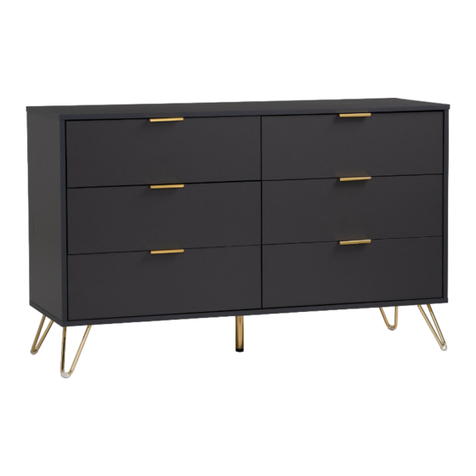
nuhoom
nuhoom VOLOS 344022 User manual
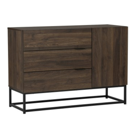
nuhoom
nuhoom CAPRI 343038 User manual

nuhoom
nuhoom MANDO 372048 User manual
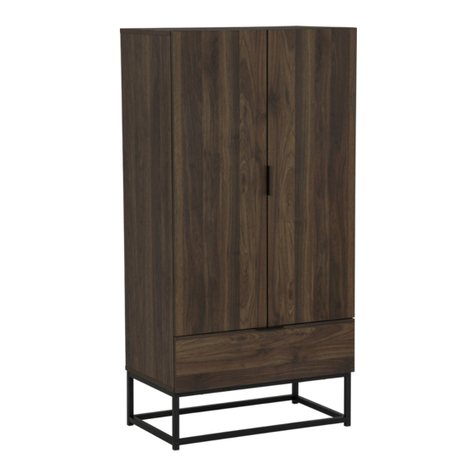
nuhoom
nuhoom CAPRI 372050 User manual
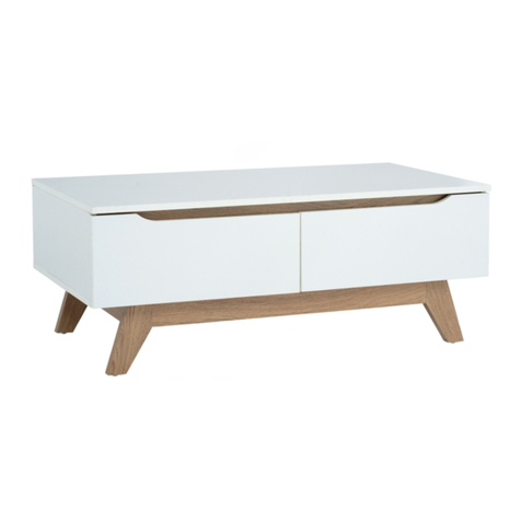
nuhoom
nuhoom MANDO 133081 User manual
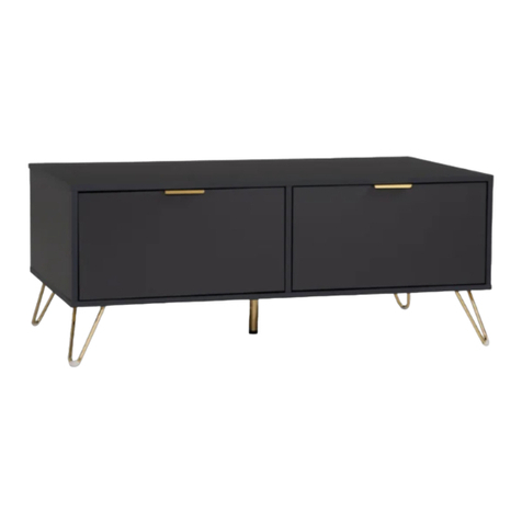
nuhoom
nuhoom VOLOS 133082 User manual

nuhoom
nuhoom VOLOS 336046 User manual
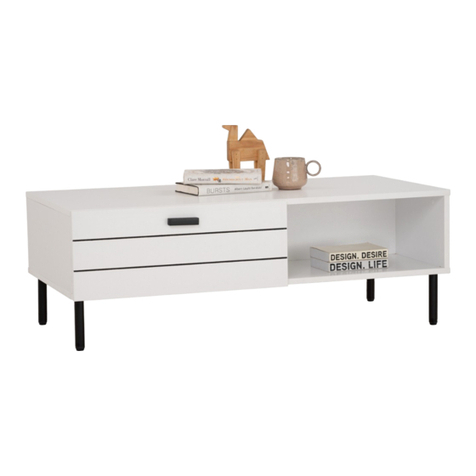
nuhoom
nuhoom KOTKA 133083 User manual
Popular Indoor Furnishing manuals by other brands

Regency
Regency LWMS3015 Assembly instructions

Furniture of America
Furniture of America CM7751C Assembly instructions

Safavieh Furniture
Safavieh Furniture Estella CNS5731 manual

PLACES OF STYLE
PLACES OF STYLE Ovalfuss Assembly instruction

Trasman
Trasman 1138 Bo1 Assembly manual

Costway
Costway JV10856 manual


