NuTone Advantage CV850 User manual

Built-In Central Cleaning System
MODEL: CV850
SYSTEM PLANNING AND LAYOUT . . . . . . . . . . . . . . . . . . . . . .2
Examples . . . . . . . . . . . . . . . . . . . . . . . . . . . . . . . . . . . . . . . . . . . .2
Locating the Power Unit . . . . . . . . . . . . . . . . . . . . . . . . . . . . . . . . .3
Tubing and Wall Inlet Location . . . . . . . . . . . . . . . . . . . . . . . . . . .3
Locating Access Keys in Existing Construction . . . . . . . . . . . . . . .3
INSTALLATION IN NEW CONSTRUCTION . . . . . . . . . . . . . . . .4-8
Wall Inlet Rough-In . . . . . . . . . . . . . . . . . . . . . . . . . . . . . . . . . . . .4
Installing the Tubing . . . . . . . . . . . . . . . . . . . . . . . . . . . . . . . . . . . .5
Wall Inlet Installation
Models CI370 & 360 Wall Inlets . . . . . . . . . . . . . . . . . . . . . . . . .6
Model 330 Wall Inlet . . . . . . . . . . . . . . . . . . . . . . . . . . . . . . . . .6
Model CI390 Wall Inlet (Electrified Inlet) . . . . . . . . . . . . . . . . . .7
POWER UNIT INSTALLATION . . . . . . . . . . . . . . . . . . . . . . . . . . .8
Dimensional Chart . . . . . . . . . . . . . . . . . . . . . . . . . . . . . . . . . . . .8
Mounting . . . . . . . . . . . . . . . . . . . . . . . . . . . . . . . . . . . . . . . . . . .8
Tubing Connections at Power Unit . . . . . . . . . . . . . . . . . . . . . . .8
Wiring . . . . . . . . . . . . . . . . . . . . . . . . . . . . . . . . . . . . . . . . . . . . . .8
INSTALLATION IN EXISTING CONSTRUCTION . . . . . . . . . . .9-10
Wall Inlet Installation
Models CI370 & 360 Wall Inlets . . . . . . . . . . . . . . . . . . . . . . . . .9
Model 330 Wall Inlet . . . . . . . . . . . . . . . . . . . . . . . . . . . . . . . .10
FLOOR INLET INSTALLATION . . . . . . . . . . . . . . . . . . . . . . .10-11
FINAL SYSTEM CHECK . . . . . . . . . . . . . . . . . . . . . . . . . . . . . . . .11
WARRANTY . . . . . . . . . . . . . . . . . . . . . . . . . . . . . . . . . . . . . . . . .12
INSTALLATION
INSTRUCTIONS

2
SYSTEM PLANNING AND LAYOUT
The NuTone Central Cleaning System consists of a Power Unit,
PVC Tubing and Fittings, Wall Inlets, a flexible Hose and various
cleaning Attachments.
The Power Unit is designed to be wall-mounted away from the
living area of the home and connected to the living area by
means of permanently installed in-wall tubing, fittings and inlets.
Generally, an installation will require 3 to 4 inlets and 16 to 20
feet of tubing per inlet. It is suggested that a floor plan be used to
more accurately determine the quantity of materials needed.
As an aid in planning the installation in either new or existing
construction, look at the following examples. You should be able
to adapt the examples shown to your specific home layout.
Here the power unit is mounted
in the garage. The intake and
exhaust tubing, the only exposed
tubing in the installation, runs up
the garage wall and into the attic.
The trunk line runs horizontally
through the attic from the power
unit to the farthest inlet location.
Branch lines spread throughout the
attic, connecting the trunk line to the
inlet tubing. Each inlet tube is
threaded vertically through an inside wall.
Located in hallways, and in large rooms, the inlets are placed to
provide maximum access to all cleaning areas. See Figure 1.
EXHAUST
TRUNK LINE
BRANCH LINE
INLETS
POWER
UNIT INTAKE
INLET LINE
VERTICAL
BRANCH
LINE
ATTIC
TRUNK
LINE
INLET
LINE
INLET
EXHAUST
INTAKE
POWER
UNIT
BASEMENT
TRUNK LINE
FIGURE 2
FIGURE 1
Like the two-story house, the split level installation
commonly calls for a two-level trunk line. Here,
the power unit is located in the garage.
The intake tubing runs exposed up the
garage wall and into the ground level
section's attic. Two branch lines
connect this part of the trunk
line to inlet lines which are
dropped inside interior walls. A
vertical branch line runs to the
upstairs attic, where the trunk
line branches into a T-shape.
This trunk line connects to two
upstairs inlet lines and to one
inlet line which drops through
an upstairs wall and down into
the third-level utility room to service
this entire level. See Figure 3.
EXHAUST
POWER
UNIT
INTAKE
TRUNK
LINE
VERTICAL
BRANCH
LINE
BRANCH
LINES
INLET
LINE
INLET
INLET
BRANCH
LINE
THE RANCH STYLE HOUSE
THE TWO-STORY HOUSE
THE SPLIT-LEVEL HOUSE
A double-trunk line system is commonly used in two-story houses.
In the installation shown at left, the power unit is mounted in the
basement. The intake tubing runs up the basement wall and
connects to the main trunk line, which runs along the unfinished
basement ceiling. Two first-floor inlets are connected to the basement
trunk line by vertical inlet lines run through interior walls. In the center
of the house, a vertical branch line runs from the basement trunk line,
through stacked closets, up into the attic. A second trunk line runs across
the attic and two branch lines connect to inlet lines which are dropped
down through upstairs interior walls. See Figure 2.
FIGURE 3

3
• Locate the power unit away from the general living area in an
accessible location for changing the soil bag and periodically
cleaning the secondary filter.
• When planning, remember the power unit is equipped with
an inlet to service a garage, basement, utility room, etc.,
wherever it is located.
• Locate the power unit within six feet of a grounded electrical
outlet. The power unit requires a 240vAC, 15 amp circuit with
a NEMA 6-15R receptacle.
• Do not locate the power unit close to a source of extreme
heat (i.e., water heater) or in an area with a high ambient
temperature (i.e., attic, furnace room).
• If the power unit is located in a closet or a small utility room,
make sure the area is well-ventilated (i.e., with door louvers).
• Exhausting the power unit to the outside is recommended for
optimal performance but is not required. The exhaust should
not be vented into a wall, a ceiling or a concealed space in
the house. If the exhaust line is vented outside the home,
Model 393 Wall Cap or a roof vent are recommended.
WARNING: Power unit must not be mounted in a high
ambient temperature area such as attic, furnace room, etc.
TUBING AND WALL INLET LOCATIONS
1. Locate inlets on interior walls, choosing central locations
which allow several rooms to be cleaned from a single inlet
using a 30 foot long hose.
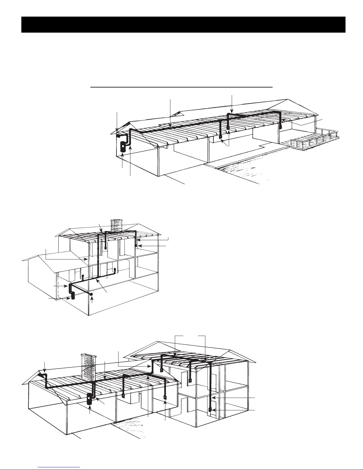
2. The tubing installation should consist of a main trunk line
running from the farthest wall inlet to the power unit
location, with branch lines running to each additional inlet.
Keep all tubing lines as straight as possible and use as few
fittings as possible. Beginning at the area farthest from the
power unit, choose a tentative inlet location. Measure 30
feet from the proposed inlet location to the farthest corner of
the rooms to be cleaned by that inlet to determine if inlet
location is proper.
3. If working from blueprints (or building plans drawn at
1⁄4" = 1 ft. scale), use a 71⁄2" chain as your guide to
determine inlet locations.
4. Move tentative inlet location if necessary. Use the same
procedure to determine each additional inlet location,
always working toward the power unit.
5. Be sure tubing will not interfere with electrical, plumbing or
other mechanical installations.
6. Locate inlets within six feet of an electrical receptacle to
allow use of optional current-carrying hose.
7. Be sure inlets will not be blocked by doors or furniture.
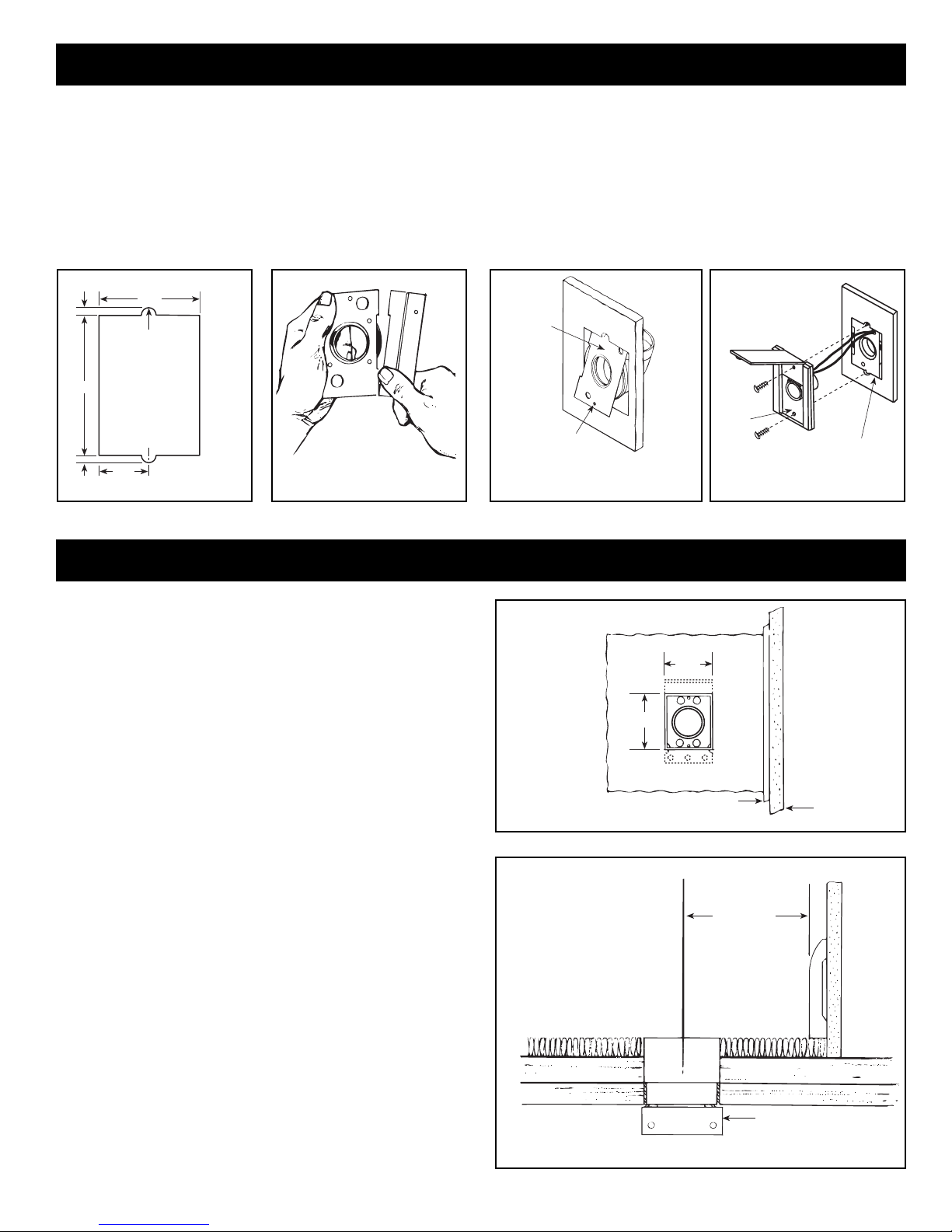
LOCATING THE POWER UNIT
Built-In Appliances. You will often
find a hollow space behind built-in
kitchen appliances. If this space lines
up with an obstruction-free interior wall
above or a closet, this might be a key
to your installation. See Figure 5.
You may also want to consider
running exposed tubing through
cabinets or cupboards.
Cold-Air Return. A cold-air
return often provides a straight
run from basement to other levels
of the house. See Figure 6.
The ductwork is easily cut for
access. Seal around the tube
when completing the installation.
FIGURE 5
FIGURE 6
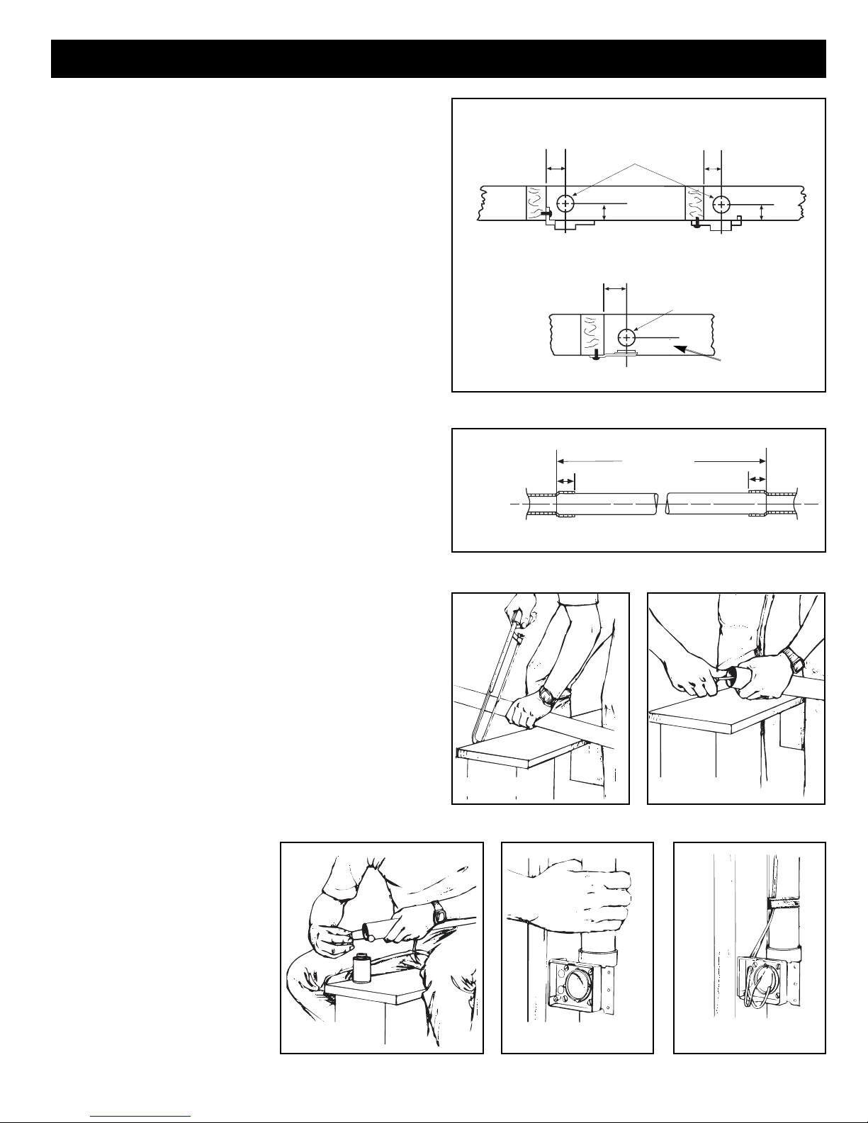
LOCATING ACCESS KEYS IN
EXISTING CONSTRUCTION
Let's say, for example, you have a two-story house and you want
to locate the power unit in the basement. If you can't find interior
walls on both the first and second floors which line up and are free
from obstacles. How do you get from the basement to the attic?
Unless your home is a ranch-style house where a single trunk
line can run directly through the attic or basement, you should first
investigate your house to find the key to running your tubing from
level to level. Look for an accessible area free from obstructions
that will accommodate the 2" tubing.
If you understand how your existing home is constructed, it can
be relatively easy to find access routes to run the tubing. Refer
again to the illustration on page 2 as you consider your home
construction.
Some of the keys you might find in your home are illustrated here.
FIGURE 4
Stacked Closets or Laundry
Chute. Many homes will have
an upstairs closet located
directly above a downstairs
closet. It is easy to run the
tubing from one floor level to
another inside these stacked
closets. In these installations
the tubing is often left exposed
inside the closets. See Figure
4. A laundry chute could also
provide access from basement
to upper floors.
TUBING

4
INSTALLATION IN NEW CONSTRUCTION
Once the locations for wall inlets have been determined, mount
all inlet brackets.
1. Choose the appropriate mounting bracket for the inlet being
installed. (See chart.)
2. To locate bracket on wall stud, measure approximately 18" up
from finished floor level. (Height may vary according to
individual preference.)
MODEL 361 (FOR USE WITH CI370 AND 360 INLETS)
3. Refer to Figure 7. Nail bracket to side of stud so that front
edge of bracket is flush to front of stud. (The bracket may also
be nailed to the front edge of the stud. See face mounting
illustrated. For face mounting, use locating tabs on bracket for
proper alignment.)
4. Refer to Figure 8. Remove cardboard from plaster guard
frame. Using four (4) provided screws, attach the appropriate
flanged fitting and inlet seal to back of inlet.
5. Replace cardboard in plaster guard frame.
MODEL 329 (FOR USE WITH 330 INLETS)
6. When using Model 329, glue elbow to mounting plate. Attach
to stud as shown in Figure 9.
SIDE
MOUNTING FACE
MOUNTING
MODEL 361
23/8"113/16"
FIGURE 7
FIGURE 8
WALL INLET ROUGH-IN
MODEL 329
FIGURE 9
NuTone Inlet Rough-in
330 Series 329
360 Series 361
CI370 Series Indicating Inlet 361
CI390 Series Electrified Inlet CI390RK

5
INSTALLATION IN NEW CONSTRUCTION (continued)
Use the following installation guidelines when installing tubing.
1. Start tubing installation at farthest inlet and work toward the
power unit.
2. Tubing run to the power unit should be as straight as
possible.
3. When assembling sections with elbows and tees, make
sure the curve in the fitting is aligned so that the air flows
toward the power unit.
4. Branch lines should always join the trunk line from above or
from the same level. Never join a branch line from an angle
below the trunk line.
5. Refer to Figure 28 on page 8. Run low voltage wiring
(Model 376-UL) and secure wiring to tubing as tubing is
installed. Model CF-380 Pipe Support can be used to
support long runs of tubing (position near joists) and to clip
wire along tubing. Secure tubing to joists or studs. Leave
approximately 6" of wire for connection to each inlet.
6. Cut a 21⁄2" diameter hole in sole plate, header or stud
directly in line with opening of inlet bracket fitting.
Note Figure 6 for center line dimensions.
7. Refer to Figure 11. Measure length of tubing needed to
connect inlet to trunk line. Allow approximately 3⁄4" of tubing
for inserting into fittings.
8. Refer to Figure 12. Cut tubing, keeping cut square.
9. Refer to Figure 13. Remove burrs from both inside and
outside of tubing.
10. Before cementing, pre-assemble section to inlet fitting,
check for proper length.
11. Refer to Figure 14. Apply PVC cement (Model 379) to
outside of tubing. Coat tubing approximately 1" back. Take
care to keep cement from inside of tube.
12. Refer to Figure 15. Insert tubing into fitting with a twisting
motion to evenly spread cement. Be sure tubing is firmly
seated in fitting.
13. If fittings have been attached to tubing at the end opposite
the inlet bracket, be sure alignment is proper before
cement sets.
14. Refer to Figure 16. Tape wire to tubing to hold in place
and insert through hole in inlet bracket.
15. Connect each inlet line and branch line into main trunk line.
Complete low voltage wiring as main trunk line is continued
back to power unit.
INSTALLING THE TUBING
SIDE
MOUNTING FACE
MOUNTING
MODEL 361 MOUNTING
21/2" DIA. HOLE
THROUGH SOLE PLATE
23/8"113/16"
MODEL 329 MOUNTING
2"
FACE
MOUNTING
113/16"
113/16"
21/2" DIA. HOLE
THROUGH SOLE PLATE
113/16"
FIGURE 10
FIGURE 11
INCLUDE FITTING
RECESS IN
MEASUREMENT
TUBING MEASUREMENT
PVC TUBING
FITTING FITTING
3/4"
3/4"
FIGURE 12 FIGURE 13
FIGURE 14 FIGURE 15 FIGURE 16
2" - 382S
25⁄8" - 382
Caution: When tubing is run
through the wall stud, sole plate,
headers - or anywhere that
building materials will be
attached - place a nail plate
(Model 378) over that area
(on both sides if necessary)
to prevent nails from piercing
tubing.

6
INSTALLATION IN NEW CONSTRUCTION (continued)
FIGURE 19
FIGURE 21
MODEL 365
DOUBLE FLANGED
TEE WALL
INLET
MOUNTING
BRACKET
SHORTEN
WALL
FIGURE 17
FIGURE 22
Your CV850 Power Unit is designed especially for model CI370
Series Indicating Inlets. These inlets include a LED to remind you
after 25 hours of operation that it is time to change the filter bag in
your power unit. Any other NuTone inlets may
be used as well.
MODEL CI370 WALL INLET (361 Rough-In)
1. Remove the cardboard plaster guard.
2. Refer to Figure 17. For some drywall or panel construction, the
plaster frame will extend beyond the finished wall. In this case,
remove plaster frame from mounting bracket by removing
mounting screws.
NOTE: When using the Model 361 inlet bracket on walls thinner
than 1⁄2", use a 1⁄4" spacer (not furnished) between the wall and the
inlet bracket. See Figure 20. Spacer may be made from plywood,
Masonite™, etc. Contact cement may be used to hold spacer in
place during assembly. Configuration of spacer may vary
depending upon installation.
3. Refer to Figure 18. Connect the red striped wire of the 2-
conductor low voltage cable to the unused terminal screw on
the inlet. Connect the remaining wire to the black pigtail wire.
Cap off both wires using wire nut (supplied).
NOTE: The LED indicator light used in the CI370 is polarity
sensitive. If the 2-conductor cable used to connect the inlet to the
power unit does not have a polarity marking and the CI370 is
wired backwards, no damage will result; however, the indicator will
light RED instead of GREEN when the hose is inserted into the
inlet. To correct this condition, simply reverse the 2-conductor
connections at the CI370 inlet.
4. Guide excess wire back through the hole in inlet bracket and
flanged fitting
5. Refer to Figure 19. Place inlet into mounting bracket and
secure.
NOTE: when wall inlets are installed in walls that are less
than 1⁄2" thick or when inlets are installed back-to-back in a
wall, the tube of the wall inlet may extend into elbow area of
the flanged fitting and cause blockage. Shorten the wall inlet
tube to prevent this condition. Refer to Figure 21.
For extra thick walls, use Model 399 Extension Sleeve to connect
inlet to the flanged fitting.
MODEL 360 WALL INLET (361 Rough-in)
1. Follow steps 1-2 as above.
2. Refer to figure 22. Connect 2-conductor low voltage wire to
terminal screws on back of wall inlet.
3. Follow steps 4-5 as above.
MODEL 330 WALL INLET (329 Rough-in)
See Figure 23.
1. Connect 2-conductor low voltage wire to terminal screws on
back of wall inlet.
2. Align inlet mounting holes with holes in mounting plate.
3. Place inlet into mounting plate and secure with two provided
screws.
MOUNTING
PLATE
INLET
FIGURE 23
WALL INLET INSTALLATION
21/4"31/4"
1/4"
INLET MOUNTING
BRACKET
SPACER WALL LESS THAN
1/2" THICK.
PLASTER
GUARD
HOLE
FIGURE 20
FIGURE 18
SCREW
TERMINAL
RED
STRIPED
WIRE
BLACK
PIG TAIL
WIRE
NUT

7
INSTALLATION IN NEW CONSTRUCTION (continued)
1. See Figure 24. Fasten the mounting plate to a stud within
three studs (48") of an electrical outlet box. Measure and
mark the wire 10" from the plug (A). Feed the wire through
the top hole in the mounting plate (just above the circular
opening). Snap the molded plug into the mounting plate as
pictured (B). This will keep it secure and out of harm’s way
during drywalling and finishing. Line up the wire at the
previously measured 10" mark with the strain of relief
channel on the back of the mounting plate. Secure it in
place with the supplied wire tie (C).
2. Run the inlet wire to the adjacent electric box. If you must
run wire through a stud, drill directly through the center of
the stud (D).
3. See Figure 25. Place the exposed ends of the two wires
into the electrical box through a strain relief channel (E).
Tighten the strain relief channel (do not overtighten) on the
white sheathing leaving 1/2" of this sheathing exposed
inside of the outlet box.
Fold the 6" of black and white wire into the outlet box.
Leave the wires to be connected by the electrician when
plug receptacles are being installed. (Attention: Power
tools such as routers are not recommended for use with
the inlet installation, as removal of drywall with these
devices may cause damage to the mounting plate and/or
inlet plug).
4. Once drywall and finishing processes have been
completed, remove molded plug from mounting plate (with
the aid of a slot screwdriver) and snap it into the wing slot
at the back of the inlet (F). (Please note: molded plug fits
one way only, with the narrow opening at the top). Insert
inlet into the mounting plate and secure inlet to mounting
plate with screws provided.
NOTE: All electrical devices such as the electrified inlet
should be reported to the construction electrician for listing
on the inspection report for building inspection purposes.
NOTE: Plumb inlet to tubing using NuTone Model 382-S 90°
Ell fitting.
CI-390 ELECTRAVALVE™ ELECTRIFIED INLET INSTALLATION (CI-390RK Rough-In)
(Not available in Canada)
D
E
FIGURE 24
FIGURE 25

8
1. The CV850 is designed with dual independent exhaust. Separate
exhaust lines are recommended.
2. Using rubber couplings and hose clamps to connect intake and
exhaust tubing.
3. Connect intake tubing to intake tube on power unit.
4. Connect mufflers and exhaust tubing to upper exhaust tubes on
the power unit.
5. Make sure all tubing connections are air tight.
6. The exhaust should not be vented into a wall, ceiling or concealed
space in the house. Exterior vented exhaust lines should be term-
inated using Model 393 Wall Caps or appropriate louvered
exhaust vents.
DIMENSIONAL CHART
DIMENSION CV850
A36
1
⁄
4
"
B10
1
⁄
2
"
C 12"
D15
3
⁄
4
"
E6
1
⁄
2
"
POWER UNIT INSTALLATION
FIGURE 26
LOWER
SLOT
111/2"
MOUNTING
BRACKET
TOP KEYHOLE SLOT
"E"
INTAKE
FIGURE 27 FIGURE 28
TUBING CONNECTIONS AT POWER UNIT
MOUNTING See Figure 26. Also refer to page 3.
1. Locate power unit within six feet of a grounded electrical outlet.
2. Drill
3
⁄
16
" diameter pilot holes for the two (2) mounting screws in a wall
stud or strong support. See Figure 27.
3. Tighten mounting screws. Leave approximately
1
⁄
8
" to
3
⁄
16
" clearance
between head of screw and wall.
4. Hang power unit onto mounting screws. Make sure top keyhole slot
and lower slot in mounting bracket are engaged behind mounting
screws. Pull down to secure.
5. Remove lower canister from power unit. Make sure bag is properly
installed in power unit. Remove extra bag and homeowner’s manual.
Securely replace canister.
WIRING See Figure 28.
Grounding Instructions – This appliance must be grounded. If it
should malfunction or break down, grounding provides a path of least
resistance for electric current, to reduce the risk of electric shock. This
appliance is equipped with a cord having an equipment-grounding
conductor and grounding plug. The plug must be plugged into an
appropriate outlet that is properly installed and grounded in accordance
with all local codes and ordinances.
Danger – Improper connection of the equipment-grounding
conductor can result in a risk of electric shock. Check with a qualified
electrician or service person if you are in doubt as to whether the outlet
is properly grounded. Do not modify the plug provided with the
appliance – if it will not fit the outlet, have a proper outlet installed by a
qualified electrician.
This appliance is for use on a nominal 240VAC, 15 amp circuit with
NEMA 6-15R receptacle. Make sure that the appliance is connected to
an outlet having the same configuration as the plug. No adapter should
be used with this appliance.
1. Connect low voltage wire (18 gauge, 2-conductor, Model 376-UL) to
crimp connectors located on outside of the power unit.
2. The power unit is equipped with a six foot grounded cord.
Plug cord into 240VAC, 15 amp grounded receptacle.
MINIMUM WALL CLEARANCE DIMENSIONS
EXHAUST
INTAKE
TOP VIEW
“D”
12" 18"
12" MINIMUM TO CEILING
FRONT VIEW
INTAKE
EXHAUST
18" MINIMUM ABOVE FLOOR
“A”
OVERALL
HEIGHT
“B”
TOP OF
UNIT TO
TOP
KEYHOLE
SLOT “C”
NOTE: INLET LEADS TO BE
CONNECTED TO POWER UNIT
TERMINALS USING THE 1/4"
PUSH-ON CONNECTORS ON
POWER UNIT.
WIRING
POWER
CORD
PUSH-ON
CONNECTORS
INLET
LEADS
INLET INLET INLET
TO
OTHER
INLETS
MODEL 376-UL (18/2) WIRE
240VAC ELECTRICAL
OUTLET POWER
UNIT
Note: The Power Unit utilizes
two (2) mufflers that may be
positioned up, down or
horizontally

9
Use the following procedures for installation in existing construction.
Starting from farthest wall inlet location, install each inlet as described
below. Working back toward power unit, connect each inlet line and
branch line into main trunk line. See page 5. Complete low voltage wiring
as main trunk line is continued back to power unit. Mount power unit and
complete wiring. See page 8.
1. See Figure 29. A small ‘pilot’ or ‘locating’ hole can be drilled behind
baseboard toe strip to determine proper location of 21⁄2" diameter tubing
hole in sole plate.
2. Measure the total thickness of the wall, including baseboard. One half of
this wall thickness measured from the pilot hole (dimension ‘X’) will
determine the proper location of the 21⁄2" tubing hole in the sole plate.
3. Once desired inlet locations have been determined, cut a 21⁄2" hole in
sole plate directly in line with proposed inlet location. Check through
tubing hole to be sure no obstruction exists.
4. Be sure tubing hole is centered in sole plate and directly in line with
proposed wall inlet cutout.
BASEBOARD
TOE STRIP
PILOT HOLE
“X”
SOLE PLATE
FIGURE 29
NOTE: If 330 Wall Inlet is being used refer to Model 330 Wall Inlet
Installation on next page.
5. If area is clear, cut an inlet opening in the wall approximately 18" above the floor.
Make sure wall opening and 21⁄2" tube hole line up (Figure 30).
6. Cut a length of tubing that will extend from inlet opening to a point below floor level
(or above ceiling level in attic installation). Tape low voltage wire to tube and insert tube
through predrilled hole to a level opposite the wall opening.
7. Apply cement to tube and install flanged wall fitting. Make sure fitting is well seated
and sealed (Figure 31).
8. Remove plaster frame from mounting bracket. Pull low voltage wire through hole in
bracket and insert bracket into cutout. Secure bracket to flanged fitting with four screws
provided. Be sure seal is secure between flange fitting and
mounting bracket (Figure 32).
9. Attach the low voltage wires to terminal screws on back of wall
inlet (Figure 33). If using 361 Rough-in with CI370 Series Inlets,
refer to instructions on page 6, step 3, shown in Figure 18.
10. Insert wall inlet into bracket and secure with the two screws
provided (Figure 34).
21/2"
29/16"
31/16"
18"
FIGURE 30
FIGURE 32
FIGURE 33 FIGURE 34
LOW
VOLTAGE
WIRING
FLANGED
FITTING
FIGURE 31
INSTALLATION IN EXISTING CONSTRUCTION
NOTE: If the wall for mounting the Model 360 inlet is less
than 1⁄2", a spacer must be used. See Figure 20 on page 6 as
a guide.
WALL INLET INSTALLATION
MODEL CI370 or 360 SERIES INLETS (361 Rough-In)

10
INSTALLATION IN EXISTING CONSTRUCTION (continued)
MOUNTING
PLATE
MOUNTING
HOLE (2)
ELBOW
FIGURE 37
MOUNTING
PLATE
INLET
FIGURE 38
1. Make cutout according to dimensions in Figure 35.
2. Refer to Figure 36. Break off nail plate at scored line.
3. Refer to Figure 37. Glue elbow to mounting plate, place
assembly into cutout, and attach elbow to tubing inside
the wall.
4. Make sure mounting holes are exactly at top and bottom.
13/8"
1/4"
3/8" DIA.
3/8" DIA.
1/4"23/4"
37/8"
FIGURE 35 FIGURE 36
MODEL 330N WALL INLET INSTALLATION (329 Rough-in)
5. Connect 2-conductor low voltage wire to terminal screws on
back of wall inlet.
6. Refer to Figure 38. Align inlet mounting holes with mounting
plate holes, place inlet into mounting plate, and secure with
provided screws. NOTE: If 382-S shorter radius elbow is
used, it may be necessary to use the short mounting screw to
avoid interference with elbow.
FLOOR INLET INSTALLATION IN NEW & EXISTING CONSTRUCTION
1. Refer to Figures 39 and 40. After floor inlet location has been
selected, cut a 31⁄16" x 29⁄16" square hole in floor. Center line of
inlet must be located at least 21⁄2" from wall to allow cover to
be opened when hose is inserted.
2. Determine direction of tubing and attach appropriate flanged
fitting to mounting bracket with four (4) screws supplied. Be
sure mounting bracket flange does not interfere with
tubing and seal is securely in place.
3. Refer to Figure 41. Position bracket with frame and flanged
fitting assembly into cutout from below and secure to sub
floor.
4. Refer to Figure 42. Large end of Model 399 extension sleeve
should be cut to length to allow proper seating of inlet against
floor or carpet.
5. Refer to Figure 43. Pull low-voltage 2-conductor wire through
mounting bracket and attach to terminal screws on back of
floor inlet. Cement extension sleeve to Model CI370 or 360
inlet. Insert extension sleeve through vinyl gasket in mounting
bracket and firmly seat into flanged fitting.
6. For convenience of operation, floor inlet should be installed to
open back toward wall.
7. Refer to Figure 41. Secure floor inlet in place with two screws.
MOLDING WALL
TOP VIEW
29/16"
31/16"
FIGURE 39
21/2" MIN.
APPROX.
SIDE VIEW
MOUNTING BRACKET
FLANGE
FIGURE 40
MODEL CI370 OR 360 SERIES INLETS (361 Rough-in)

11
FLOOR INLET INSTALLATION
FLOOR
SUB-FLOOR
29/16"31/16"
INLET
EXTENSION
FLOOR
INLET
FRAME
MOUNTING
BRACKET
SEAL
FLANGED
FITTING
FIGURE 41
CUT TO
LENGTH
EXTENSION
SLEEVE
FLANGED
FITTING
MOUNTING
BRACKET
FLANGE
FIGURE 42
WALL
INLET
EXTENSION SLEEVE
BRACKETFLANGED FITTING
TUBING
FIGURE 43
FINAL SYSTEM CHECK
Be sure all inlets are closed and soil bag is in place. Check
switch on power unit for manual on/off operation. Check that
indicator light on side of power unit is lit and is in green mode.
Check each wall inlet to be sure contacts activate power unit
when hose is inserted and switched on, if applicable. If using
CI370 Indicating Inlet, be sure LED on inlet is green when hose
is inserted/switched on. If Central Cleaning hose is not available
at the time, a short piece of wire can be used to short contacts in
wall inlet to activate power unit. Check each wall inlet and tubing
connection for air leaks. Check power unit for leaks around inlet
tube and dirt receptacle.
Make sure the filter bag is properly installed in the power unit
according to directions printed on the bag or in homeowner’s
manual. Remove the extra bag and owner's manual from the
power unit dirt receptacle. It may be convenient to store them
with the cleaning tools and accessories.
Now it’s time to enjoy the benefits of a NuTone Central Cleaning
System.
INLET

NuTone Power Units are covered by NuTone 2 Year warranty.
All other Central Cleaning products are warranted for one year from date of purchase.
Product specifications subject to change without notice.
Printed in U.S.A., Rev. 4/01, Part No. 88367
4820 Red Bank Road, Cincinnati, Ohio 45227
1140 Tristar Drive, Mississauga, Ontario, Canada L5T 1H9
www.nutone.com
®
Two Year Limited Warranty
WARRANTY OWNER: NuTone warrants to the original consumer purchaser of its products that such products will be free from defects in materials or workmanship for a period
of two (2) years from the date of original purchase. THERE ARE NO OTHER WARRANTIES, EXPRESS OR IMPLIED, INCLUDING, BUT NOT LIMITED TO, IMPLIED
WARRANTIES OF MERCHANTABILITY OR FITNESS FOR A PARTICULAR PURPOSE.
During this two year period, NuTone will, at its option, repair or replace, without charge, any product or part which is found to be defective under normal use and service.
THIS WARRANTY DOES NOT EXTEND TO FLUORESCENT LAMP STARTERS OR TUBES, FILTERS, DUCT, ROOF CAPS, WALL CAPS AND OTHER ACCESSORIES
FOR DUCTING. This warranty does not cover (a) normal maintenance and service or (b) any products or parts which have been subject to misuse, negligence, accident,
improper maintenance or repair (other than by NuTone), faulty installation or installation contrary to recommended installation instructions.
The duration of any implied warranty is limited to the one year period as specified for the express warranty. Some states do not allow limitation on how long an implied warranty
lasts, so the above limitation may not apply to you.
NUTONE’S OBLIGATION TO REPAIR OR REPLACE, AT NUTONE’S OPTION, SHALL BE THE PURCHASER’S SOLE AND EXCLUSIVE REMEDY UNDER THIS
WARRANTY. NUTONE SHALL NOT BE LIABLE FOR INCIDENTAL, CONSEQUENTIAL OR SPECIAL DAMAGES ARISING OUT OF OR IN CONNECTION WITH
PRODUCT USE OR PERFORMANCE. Some states do not allow the exclusion or limitation of incidental or consequential damages, so the above limitation or exclusion may
not apply to you. This warranty gives you specific legal rights, and you may also have other rights, which vary from state to state. This warranty supersedes all prior warranties.
WARRANTY SERVICE: To qualify for warranty service, you must (a) notify NuTone at the address stated below or telephone 1/800-543-8687, (b) give the model
number and part identification and (c) describe the nature of any defect in the product or part. At the time of requesting warranty service, you must present
evidence of the original purchase date.
Date of Installation Builder or Installer
Model No. and Product Description
IF YOU NEED ASSISTANCE OR SERVICE:
For the location of your nearest NuTone Independent Authorized Service Center:
Residents of the contiguous United States Dial Free 1-800-543-8687
Please be prepared to provide:
Product model number • Date and Proof of purchase • The nature of the difficulty
Residents of Alaska or Hawaii should write to: NuTone Inc. Attn: Department of National Field Service, 4820 Red Bank Road, Cincinnati Ohio 45227-1599.
Residents of Canada should write to: Broan-NuTone Canada, 1140 Tristar Drive, Mississauga, Ontario, Canada L5T 1H9.
Rev. 03/2001

Système Central d’Aspiration Intégré
MODELE: CV850
PLANIFICATION ET DISPOSITION DU SYSTEME . . . . . . . . . . .2
Exemples . . . . . . . . . . . . . . . . . . . . . . . . . . . . . . . . . . . . . . . . . . . .2
Emplacement du Groupe d’Aspiration . . . . . . . . . . . . . . . . . . . . . .3
Tuyauterie et Emplacement des Prises Murales . . . . . . . . . . . . . .3
Emplacement des Points d’Accès dans une
Construction Existante . . . . . . . . . . . . . . . . . . . . . . . . . . . . . . . . . .3
INSTALLATION DANS UNE NOUVELLE CONSTRUCTION . . .4-8
Encastrement de Prise Murale . . . . . . . . . . . . . . . . . . . . . . . . . . .4
Installation de la Tuyauterie . . . . . . . . . . . . . . . . . . . . . . . . . . . . . .5
Installation des Prises Murales
Modèles CI370 et 360 Prises d’Aspiration Murales . . . . . . . . . .6
Modèle 330 Prise Murale . . . . . . . . . . . . . . . . . . . . . . . . . . . . . .6
Modèle CI390 Prise Murale (Electrifiée) . . . . . . . . . . . . . . . . . .7
INSTALLATION DU GROUPE D’ASPIRATION . . . . . . . . . . . . . .8
Tableau des Dimensions . . . . . . . . . . . . . . . . . . . . . . . . . . . . . . . .8
Montage . . . . . . . . . . . . . . . . . . . . . . . . . . . . . . . . . . . . . . . . . . . . .8
Raccords de la Tuyauterie au niveau du Groupe d’Aspiration . . .8
Câblage . . . . . . . . . . . . . . . . . . . . . . . . . . . . . . . . . . . . . . . . . . . . .8
INSTALLATION DANS UNE CONSTRUCTION EXISTANTE .9-10
Installation des Prises Murales
Modèles CI370 et 360 Prises Murales . . . . . . . . . . . . . . . . . . . .9
Modèle 330 Prise Murale . . . . . . . . . . . . . . . . . . . . . . . . . . . . .10
INSTALLATION DES PRISES AU SOL . . . . . . . . . . . . . . . . .10-11
VERIFICATION FINALE DU SYSTEME . . . . . . . . . . . . . . . . . . . .11
GUARANTIE . . . . . . . . . . . . . . . . . . . . . . . . . . . . . . . . . . . . . . . . .12
INSTRUCTIONS
D’INSTALLATION

14
PLANIFICATION ET DISPOSITION DU SYSTEME
Le système central d'aspiration intégré de NuTone comprend un groupe
d'aspiration, une tuyauterie et des raccords en PVC, des prises
d'aspiration murales, un tuyau souple et de différents accessoires de
nettoyage.
Le Groupe d'Aspiration est conçu pour un montage mural éloigné de la
zone d'habitation de la maison mais connecté à celle-ci grâce à une
tuyauterie, des raccords et des prises installés de façon permanente dans
les murs.
Généralement une installation requiert de 3 à 4 prises avec 5 à 6 mètres
de tuyauterie par prise d'aspiration. Il est suggéré qu'un plan soit utilisé
pour mieux déterminer la quantité du matériel qui sera nécessaire.
Comme une aide dans la planification d'une installation dans une
construction nouvelle ou déjà existante, voyez les exemples suivants.
Vous devriez pouvoir adapter les exemples montrés à la disposition
spécifique de votre maison.
Dans cet exemple, le groupe
d'aspiration est monté dans le garage.
Les tuyaux d'admission et d'évacuation, les
seuls exposés de l'installation, montent le
long du mur du garage jusqu’au grenier.
La ligne principale parcourt
horizontallement le grenier en partant du
groupe d'aspiration jusqu'à l'emplacement
de la prise d'aspiration la plus éloignée. Les
lignes secondaires s'étendent à travers le
grenier, pour raccorder la ligne principale
aux tuyaux d’admission. Chaque tube
d'aspiration est installé verticallement dans
un mur intérieur. Situées dans les couloirs, et dans de grandes
pièces, les prises d'aspiration sont placées de façon à vous procurer un accès
maximum aux zones à nettoyer. Voyez la figure 1.
EXHAUST
TRUNK LINE
BRANCH LINE
INLETS
POWER
UNIT INTAKE
INLET LINE
VERTICAL
BRANCH
LINE
ATTIC
TRUNK
LINE
INLET
LINE
INLET
EXHAUST
INTAKE
POWER
UNIT
BASEMENT
TRUNK LINE
FIGURE 2
FIGURE 1
Tout comme la maison à un étage, l'installation dans une maison
à plusieurs niveaux, nécessite communément une ligne principale
à deux niveaux. Dans cet exemple, le groupe d'aspiration est
monté dans le garage. La tuyauterie d'admission exposée
monte le long du mur du garage jusqu'au grenier
du rez-de-chaussé. Deux lignes secondaires
raccordent cette partie de la ligne
principale aux lignes de prise qui
descendent à l'intérieur des murs
intérieurs. Une ligne secondaire
verticale passe dans le grenier du
premier étage, où la ligne principale
adopte la forme d'un "T". Cette
ligne principale se raccorde à
deux lignes de prise du
premier étage et a une ligne qui
descend à travers le mur jusqu'à la
buanderie pour desservir entièrement
ce niveau. Voyez la figure 3.
EXHAUST
POWER
UNIT
INTAKE
TRUNK
LINE
VERTICAL
BRANCH
LINE
BRANCH
LINES
INLET
LINE
INLET
INLET
BRANCH
LINE
LA MAISON DU STYLE "RANCH"
LA MAISON A UN ETAGE
LA MAISON A PLUSIEURS NIVEAUX
Un système de double ligne principale est communément utilisé pour les maisons
à un étage. Dans l'installation montrée à gauche,
le groupe d'aspiration est installé dans le sous-sol. Le tuyau d'admission
remonte le long d'un mur du sous-sol et se raccorde à la ligne principale qui
est installée au plafond non fini du sous-sol.
Deux prises au rez-de-chaussée sont connectées à la ligne principale du sous-sol
grâce à des lignes verticales d'admission installées dans des murs intérieurs. Dans le
centre de la maison, une ligne secondaire verticale parcourt de la ligne principale du
sous-sol à travers les placards superposés jusqu'au grenier. Une seconde ligne
principale traverse le grenier et deux lignes secondaires se raccordent à deux lignes
de prise qui descendent à travers les murs intérieurs du premier étage.
Voyez la figure 2.
FIGURE 3
EVACUATION
GROUPE
D’ASPIRATION
ADMISSION
LIGNE
SECONDAIRE
LIGNE
PRINCIPALE
PRISES
LIGNE DE
PRISE
PRISE
EVACUATION
ADMISSION
LIGNE
PRINCIPALE
DU SOUS-SOL
LIGNE
PRINCIPALE
DU GRENIER
GROUPE
D’ASPIRATION
LIGNE
SECONDAIRE
VERTICALE
LIGNE DE
PRISE
LIGNE DE
PRISE
EVACUATION
GROUPE
D’ASPIRATION
ADMISSION
LIGNE
SECONDAIRE
VERTICALE
LIGNES
SECONDAIRES
LIGNE
SECONDAIRE PRISE
LIGNE
PRINCIPALE
PRISE

15
• Installez le groupe d'aspiration éloigné de la zone d'habitation dans
un lieu facile d'accès pour changer le sac à poussière et nettoyer
périodiquement le filtre secondaire.
• Lors de votre planification, rappelez-vous que le groupe d'aspiration
est équipé d'une prise pour vous servir dans le garage, le sous-sol, la
buanderie, etc., où qu'il soit localisé.
• Installez le groupe d’aspiration à moins de 1,8 m d’une prise
électrique mise à la terre. Le groupe d’aspiration exige une source
de courant de 120 volts CA de 15 ampères avec une prise classé
6-15R par NEMA,
• Ne placez pas le groupe d'aspiration à proximité d'une source de
chaleur (par exemple, un chauffe-eau) ou dans un lieu avec une
température ambiante élevée (par exemple, le grenier, la pièce où se
trouve la chaudiere).
• Si vous installez le groupe d'aspiration dans un placard ou une petite
buanderie, faites en sorte que la pièce soit bien aérée (par exemple,
dotée d'une porte à persiennes).
• L'évacuation extérieure du groupe d'aspiration est recommandée en
vue d'une performance optimale mais elle n'est pas requise.
L'évacuation ne doit pas se faire dans le mur, un plafond ou un
espace clos de la maison. Pour une évacuation extérieure, un
chaperon mural modèle 393 ou un ventilateur de toit est
recommandé.
ATTENTION: Le groupe d'aspiration ne doit pas être monté dans
un lieu où la température est élevée tel que le grenier ou la pièce
dans laquelle se trouve la chaudière, etc.
TUYAUTERIE ET EMPLACEMENT DES
PRISES MURALES
1. Placez les prises d'aspiration murales aux murs intérieurs, en
choisissant des emplacements centraux qui permettront d'aspirer
plusieurs pièces à partir d'une seule prise et en utilisant un boyau de
9,14 m de long.
2. L'installation de la tuyauterie devrait consister en une ligne
principale partant de la prise murale la plus éloignée jusqu'à
l'emplacement du groupe d'aspiration, avec des lignes secondaires
raccordant chaque prise additionelle. En commençant par la zone la
plus éloignée du groupe d'aspiration, choisissez un emplacement
provisoire de la prise. Mesurez 9,14 m de l'emplacement provisoire
de la prise au coin le plus éloigné des pièces qui seront aspirées de
cette prise pour determiner si son emplacement est correct.
3. Si vous travailler à partir d'un plan (ou des plans de construction à
une échelle de 0,64 cm = 30,48 cm), utilisez une chaîne de 19,05
cm comme guide pour déterminer l'emplacement des prises.
4. Changez l'emplacement provisoire des prises si nécessaire. Utilisez
la même procédure pour déterminer l'emplacement des prises
supplémentaires, en vous dirigeant toujours vers le groupe
d'aspiration.
5. Soyez certain que la tuyauterie n'interfère pas avec des installations
électriques, de plomberie ou d'autres installations mécaniques.
6. Placez les prises à une distance maximum de 1,8 m de la prise pour
permettre l'utilisation d'un boyau à courant électrique fourni en
option.
7. Soyez sûr que les prises ne seront pas bloquées par une porte ou
un meuble.
EMPLACEMENT DU GROUPE D’ASPIRATION
Equipement de cuisine intégré. Vous
trouverez souvent un espace vide derrière
votre équipement de cuisine intégré. Si cet
espace s'aligne avec un mur intérieur
sans obstruction de l'étage supérieur ou
avec un placard, cela pourrait être le point
clé de votre installation. Voyez la figure 5.
Vous pourriez également envisager
d'installer la tuyauterie non intégrée à
travers les armoires ou les cabinets de
cuisine.
Le conduit de reprise d'air froid.
Un conduit de reprise d'air froid
fournit souvent un parcours direct du
sous-sol aux autres niveaux de la
maison. Voyez la figure 6. Il est facile
de découper les conduits pour y faire
passer les tuyaux. Il suffit de sceller
l'extérieur du tuyau en terminant
l'installation.
FIGURE 5
FIGURE 6
EMPLACEMENT DES POINTS D'ACCES
DANS UNE CONTRUCTION EXISTANTE
Disons, par exemple, que vous avez une maison à un étage et que
vous voulez installer le groupe d'aspiration au sous-sol. Si vous ne
pouvez pas trouver de murs intérieurs au rez-de-chaussée ou au
premier étage qui s'alignent et sont sans obstacles, comment passez-
vous du sous-sol au grenier?
A moins que votre maison ne soit du style "Ranch", au quel cas une seule
ligne principale peut être installée directement dans le sous-sol ou le
grenier, vous devez d'abord inspecter votre résidence pour déceler les
points d'accès d'un étage à l'autre pour les tuyaux. Vous devez rechercher
une zone libre de tout obstacle où vous pourrez faire passer un tuyau de
2". Si vous comprenez comment votre maison existante est construite,
cela peut être relativement facile de trouver les points d'accès pour
installer la tuyauterie. Consultez encore une fois l'illustration de la page 2
en considérant la construction de votre maison.
Certains des points d’accès que vous pourriez trouver dans votre maison
sont illustrés ci-dessous.
FIGURE 4
Placards superposés et conduit
de chute à linge. Dans certaines
résidences, un placard est situé
directement au-dessus d’un
placard au rez-de-chaussée. Il est
alors facile de faire passer le tuyau
d'un étage à l'autre en passant par
ces placards superposés. Dans de
tels cas, le tuyau passe souvent
directement dans le placard, sans
être intégré au mur. Voyez la
figure 4. Un conduit de chute à
linge peut également procurer un
accès du sous-sol aux autres
niveaux de la maison.
Tuyau

16
INSTALLATION DANS UNE NOUVELLE CONSTRUCTION
Une fois l'emplacement des prises murales déterminé, mettez en
place tous les supports de prise.
1. Choisissez les supports de fixation appropriés pour la prise à
installer. (Voyez le tableau).
2. Pour positionner le support sur le montant, mesurez
approximativement 45,7 cm au-dessus du niveau du sol fini.
(La hauteur peut varier suivant vos préférences).
MODELE 361 (CONVIENT AUX PRISES CI370 ET 360)
3. Voyez la figure 7. Clouez le support sur le côté du montant de façon
à ce que l'avant du support soit dans l'alignement avec l'avant du
montant. (Le support peut également être cloué sur l'avant du
montant. Voyez l'illustration du montage de face. Pour le montage de
face, utilisez les pattes d'alignement des supports pour un
alignement correct.)
4. Voyez la figure 8. Enlevez le carton du cadre protecteur. Utilisez les
quatres (4) vis qui vous sont fournies, pour attacher le raccord à
bride approprié ainsi que le joint à l'arrière de la prise.
5. Replacez le carton dans le cadre protecteur.
MODELE 329 (CONVIENT AUX PRISES 330)
6. Lors de l'utilisation du Modèle 329, collez le coude à la plaque de
montage. Attachez-le au montant comme il est indiqué à la figure 9.
SIDE
MOUNTING FACE
MOUNTING
MODEL 361
23/8"113/16"
FIGURE 7
FIGURE 8
ENCASTREMENT DE PRISE MURALE
MODEL 329
FIGURE 9
Prises NuTone Encastrement
Série 330 329
Série 360 361
Série CI370 Prise avec voyant lumineux 361
Série CI390 Prise Electrifiée CI390RK
INSTALLATION
DE CÔTÉ
INSTALLATION
DE FACE
6,03 cm 4,60 cm

17
INSTALLATION DANS UNE NOUVELLE CONSTRUCTION (suite)
Suivez les lignes directrices ci-dessous lors de la mise en place de la
tuyauterie.
1. Commencez l'installation de la tuyauterie par la prise la plus éloignée
et avancez vers le groupe d'aspiration.
2. La tuyauterie qui rejoint le groupe d'aspiration devrait être la plus
droite possibe.
3. Lors de l'assemblage des sections avec les coudes et les raccords
en "T", soyez sûr que la courbe du raccord est alignée de façon à ce
que l'air se dirige vers le groupe d'aspiration.
4. Les lignes secondaires devraient toujours se raccorder à la ligne
principale par le dessus ou au même niveau que celle-ci. Ne
connectez jamais une ligne secondaire avec un angle inférieur à la
ligne principale.
5. Voyez la figure 28 de la page 8. Faites passer le câblage de basse
tension (Modèle 376-UL) et fixez-le à la tuyauterie à mesure que
vous installez celle-ci. Le modèle CF-380 de support de tuyau peut
être utilisé pour soutenir de longues sections de tuyau (placez-le à
côté des solives) et pour tenir le câblage le long de la tuyauterie.
Fixez la tuyauterie aux solives ou montants. Prévoyez
approximativement 15,24 cm de câblage pour le raccordement à
chaque prise.
6. Découpez un trou de 6,35 cm de diamètre dans la plaque d'assise,
collecteur ou le montant directement en ligne avec l'ouverture du
raccord du support de prise. Voyez la figure 6 pour les dimensions
de la ligne centrale.
7. Voyez la figure 11. Mesurez la longueur du tuyau nécessaire pour
raccorder la prise à la ligne principale. Accordez approximativement
1,905 cm de tuyauterie pour insertion dans les raccords.
8. Voyez la figure 12. Coupez le tuyau, en faisant une découpe droite.
9. Voyez la figure 13. Enlevez la barbure à l'intérieur et l'extérieur du
tuyau.
10. Avant de coller, pré-assemblez la section jusqu'au raccord de la prise
pour vérifier que la longueur soit correcte.
11. Voyez la figure 14. Appliquez la colle PCV (Modèle 379) à l'extérieur
du tuyau. Couvrez le tube à 2,54 cm du bout du tuyau. Faites
attention de ne pas mettre de colle à l'intérieur du tuyau
12. Voyez la figure 15. Insérez le tuyau dans le raccord en le faisant
tourner pour étaler uniformément la colle. Soyez sûr que le tuyau soit
solidement en place.
13. Si les raccords ont été attachés au tuyau au bout opposé du support
de prise, soyez sûr que l'alignement est correct avant la prise de la
colle.
14. Voyez la figure 16. Attachez le câblage avec du scotch pour le
maintenir en place et faites-le passer par le trou du support de prise.
15. Raccordez toutes les lignes de prise et lignes secondaires à la ligne
principale. Complétez le câblage de basse tension à mesure que
vous avancez vers le groupe d'aspiration.
INSTALLATION DE LA TUYAUTERIE
SIDE
MOUNTING FACE
MOUNTING
MODEL 361 MOUNTING
21/2" DIA. HOLE
THROUGH SOLE PLATE
23/8"113/16"
MODEL 329 MOUNTING
2"
FACE
MOUNTING
113/16"
113/16"
21/2" DIA. HOLE
THROUGH SOLE PLATE
113/16"
FIGURE 10
FIGURE 11
INCLUDE FITTING
RECESS IN
MEASUREMENT
TUBING MEASUREMENT
PVC TUBING
FITTING FITTING
3/4"
3/4"
FIGURE 12 FIGURE 13
FIGURE 14 FIGURE 15 FIGURE 16
5,08 cm- 382S
6,67 cm - 382
Attention: Lorsqu’un tuyau passe à
travers un montant, une plaque
d'assise, des collecteurs ou à tout
autre endroit où vous pourriez fixer
des matériaux - installez une plaque
protectrice (Modèle 378) à cet endroit
(des deux côtés au besoin) pour
empêcher les clous de percer le
tuyau.
INSTALLATION
DE CÔTÉ
INSTALLATION
DE FACE
INSTALLATION MODÈLE 361
ORIFICE DE 6,35 cm DE DIAMÈTRE
À TRAVERS LA PLAQUE D’ASSISE
INSTALLATION
DE FACE
ORIFICE DE 6,36 cm DE
DIAMÈTRE À TRAVERS LA
PLAQUE D’ASSISE
INSTALLATION MODÈLE 329
TUYAU DE PVC
RACCORD RACCORD
TENIR COMPTE DES
RACCORDS DANS
LES MESURES
MESURE DU TUYAU
1,905 cm 1,905 cm
5,08
cm
6,03 cm
4,6 cm
4,6 cm
4,6 cm

18
INSTALLATION DANS UNE NOUVELLE CONSTRUCTION (suite)
FIGURE 19
FIGURE 21
MODEL 365
DOUBLE FLANGED
TEE WALL
INLET
MOUNTING
BRACKET
SHORTEN
WALL
FIGURE 17
FIGURE 22
Votre groupe d'aspiration CV850 est spécialement conçu pour le
modèle CI 370 de série de prises dotées d'un voyant lumineux. Ces prises
incluent un DEL pour vous rappeler que, après chaque 25 heures
d'utilisation, il est temps de changer le sac de votre groupe d'aspiration.
Toutes les autres prises de NuTone peuvent être tout aussi bien utilisées.
MODELE CI370 PRISE MURALE (ENCASTREMENT 361)
1. Enlevez le carton du cadre protecteur.
2. Voyez la figure 17. Pour certaines cloisons sèches ou constructions à
panneaux, le cadre va s'etendre au-delà du mur fini. Dans ce cas-là,
retirez le cadre du support de montage en enlevant les vis de montage.
NOTA: Quand le modèle 361 de support de prise est utilisé pour des murs
d’une épaisseur inférieure à 1,27 cm, utilisez une entretoise de 0,64 cm
(non fournie) entre le mur et le support de prise. Voyez la figure 20.
L'entretoise peut être faite de bois contreplaqué, Masonite™, etc. De
l'adhésif de contact peut être utilisé pour maintenir l'entretoise en place
pendant l'assemblage. La configuration de l'entretoise peut varier suivant
l'installation.
3. Voyez la figure 18. Connectez le fil à rayures rouges du câble de
basse tension à deux âmes à la vis de borne non utilisée de la prise.
Connectez le fil qui reste à la queue de cochon noire. Couvrez les deux
fils en utilisant un capuchon isolant (fourni).
NOTA: Le voyant lumineux DEL utilisé dans le modèle CI370 est
polairement logique. Si le câble à deux âmes utilisé pour connecter la
prise au groupe d'aspiration n'a pas les polarités marquées et que le
modèle CI370 est câblé à l'envers, il n'y aura aucun dommage; toutefois,
l'indicateur fournira une lumière ROUGE plutôt que VERTE lorsque le
boyau sera inséré dans la prise. Pour corriger cette imperfection, inversez
simplement les deux raccords à deux âmes à la prise du modèle CI370.
4. Faites passer l'excédent de câble en arrière à travers le trou du support
de la prise et le raccord à bride.
5. Voyez la figure 19. Placez la prise dans le support de montage et fixez-la.
NOTA: Lorsque les prises murales sont installées dans les murs
d’une épaisseur inférieure à 1,27 cm ou lorsque les prises sont
installées dos-à-dos dans un mur, le tube de la prise pourrait se
mettre en contact avec le coude du raccord à bride et causer des
blocages. Raccourcissez le tube de la prise murale pour éviter ceci.
Voyez la figure 21.
Pour des murs très épais, utilisez des manchons-allonge modèle 399 pour
connecter les prises au raccord à bride.
MODELE 360 DE PRISE MURALE (ENCASTREMENT 361)
1. Suivez les étapes 1-2 comme au-dessus.
2. Voyez la figure 22. Connectez le câble de basse tension à deux âmes
aux vis de borne à l'arrière de la prise murale.
3. Suivez les étapes 4-5 comme ci-dessus.
MODELE 330 DE PRISE MURALE (ENCASTREMENT 329)
Voyez la figure 23
1. Connectez le câble de basse tension à deux âmes aux vis de borne à
l'arrière de la prise murale.
2. Alignez les orifices de montage avec les orifices de la plaque de
montage.
3. Insérez la prise dans la plaque de montage et fixez-la à l'aide des deux
vis qui vous sont procurées.
MOUNTING
PLATE
INLET
FIGURE 23
INSTALLATION DES PRISES MURALES
21/4"31/4"
1/4"
INLET MOUNTING
BRACKET
SPACER WALL LESS THAN
1/2" THICK.
PLASTER
GUARD
HOLE
FIGURE 20
FIGURE 18
VIS DE BORNE
FIL À
RAYURES
ROUGES
QUEUE DE
COCHON NOIRE
CAPUCHON
ISOLANT
SUPPORT DE MONTAGE
DE LA PRISE
ENTRETOISE MUR D’EPAISSEUR
INFERIEURE À 1,27 CM
ORIFICE DU
CADRE
PROTECTEUR
MODÈLE 365
T À DOUBLE BRIDES
MUR PARTIE
ENLEVÉE SUPPORT DE
MONTAGE
PRISE PLAQUE DE
MONTAGE
PRISE
MURALE
5,72
cm
0,64
cm
8,26 cm

19
INSTALLATION DANS UNE NOUVELLE CONSTRUCTION (suite)
1. Voyez la figure 24. Attachez la plaque de montage à un montant à
une distance maximum de trois montants (1,22 m) d'un coffret de
sortie électrique. Mesurez et marquez le câble à 25,4 cm de la
prise (A). Avancez le câble à travers le trou du haut de la plaque
de montage juste au-dessus de l'ouverture circulaire. Enclenchez
la prise moulée dans la plaque de montage comme illustré (B).
Ceci le fixera en place et en sûreté durant le montage des
cloisons et les finitions. Alignez le câble sur la marque de 25,4 cm
auparavant mesurée avec le réducteur de tension situé à l'arrière
de la plaque de montage. Fixez-le avec le lien fourni (C).
2. Faites passer le câble de la prise jusqu'au coffret électrique
adjacent. Si vous devez faire passer le câble à travers le montant,
percez un trou directement à travers le centre du montant (D).
3. Voyez la figure 25. Placez les bouts exposés des deux câbles
dans le coffret électrique à travers le réducteur de tension(E).
Serrez le réducteur de tension (ne le serrez pas trop) sur la gaine
blanche laissant 1,27 cm de cette gaine exposé à l'intérieur du
coffret.
Incorporez le câble de 15,24 cm noir et blanc dans la boîte de sortie.
Laissez les câbles être connectés par un électricien lors de
l'installation des récepteurs de prises. (Attention: l'utilisation d'outils
motorisés tels que la guimbarde n'est pas recommandée pour
l'installation de la prise, vu que le retrait des cloisons avec ces
appareils pourrait causer des dommages à la plaque de montage
et/ou la prise).
4. Une fois que le montage des cloisons et les dernières étapes de
finition ont été complétés, retirez la prise moulée de la plaque de
montage (à l'aide d'un tournevis à tête plate) et enclenchez-la
dans la fente à l'arrière de la prise (F). (Notez s'il vous plaît: la
prise moulée ne s'emboîte que d'une seule façon, avec
l'ouverture étroite en haut). Insérez la prise dans la plaque de
montage et fixez-la à la plaque de montage avec les vis qui vous
sont procurées.
NOTA: Tous les appareils électriques tels que les prises électrifiées
devraient être signalés à l'électricien de construction pour les lister
sur le rapport d'inspection dans le but d'une inspection de
construction.
NOTA: Mettez la prise en ligne avec la tuyauterie en utilisant le
raccord de coude Modèle 382-S 90° de NuTone.
INSTALLATION DE LA PRISE ELECTRIFIEE ELECTRAVALVE™ CI--390
( ENCASTREMENT CI-390RK)
(NON DISPONIBLE AU CANADA)
D
E
FIGURE 24
FIGURE 25
Vue de
derrier

20
1. Le CV850 est conçu avec une double évacuation indépendante. Des
conduites d'évacuation séparées sont conseillées.
2. Au moyen de raccords de caoutchouc et de bride de tuyau, raccordez les
tuyaux d'admission et d'évacuation à l'aspirateur.
3.Raccordez la tuyauterie d'admission au tuyau d'admission du groupe
d'aspiration.
4. Raccordez les silencieux et la tuyauterie d'évacuation aux tuyaux
d'évacuation supérieurs du groupe d'aspiration.
5. Assurez-vous que tous les raccords de tuyauterie sont hermétiques.
6. L'évacuation ne devrait pas se faire dans un mur, un plafond ou un espace
clos de la maison. Pour une évacuation extérieure, un chaperon mural
modèle 393 ou un ventilateur de toit est recommandé.
TABLEAU DES DIMENSIONS
DIMENSION CV850
A 92,1 cm
B 26,6 cm
C 30,5 cm
D 40 cm
E 16,5 cm
INSTALLATION DU GROUPE D'ASPIRATION
FIGURE 26
LOWER
SLOT
111/2"
MOUNTING
BRACKET
TOP KEYHOLE SLOT
"E"
INTAKE
FIGURE 27 FIGURE 28
RACCORDS DE LA TUYAUTERIE AU NIVEAU DU
GROUPE D’ASPIRATION
MONTAGE Voyez la figure 26. Voyez également la page 3.
1. Placez le groupe d'aspiration à moins de 1,5 m d'une prise de courant mise à la
terre.
2. Percez des trous de guidage de 0,48 cm de diamètre pour les deux (2) vis de
montage dans un montant ou dans une pièce de bois de soutien. Voyez la
figure 27.
3. Vissez les vis de montage. Laissez approximativement de 0,32 cm à 0,48 cm
d'espace entre la tête de la vis et le mur.
4 .Suspendez le groupe d'aspiration aux vis de montage. Assurez-vous que l'orifice
en forme de trou de serrure et l’encoche du support de montage soient bien
engagés derrière la tête de la vis. Tirez vers le bas pour le mettre en place
5. Retirez le réservoir inférieur du groupe d'aspiration. Assurez-vous que le sac est
correctement installé dans le groupe d'aspiration. Retirez le sac supplémentaire
et votre mode d’emploi. Remettez le réservoir solidement en place.
CABLAGE Voyez la figure 28.
Instructions de mise à la terre Cet appareil doit être mis à la terre. En cas
de défaillance ou de panne, la mise à la terre constitue une voie de moindre
résistance pour le courant électrique, ce qui réduit le risque d'un choc électrique.
Cet appareil est doté d'un cordon comprenant un conducteur et une fiche de
mise à la terre. La fiche doit être branchée dans une prise de courant
correctement installée et mise à la terre, conformément aux codes et aux
règlements en vigueur.
Danger – Une mauvaise connection de ce conducteur de mise à la terre peut
constituer un risque de choc électrique. Vérifiez auprès d'un électricien qualifié
ou d'une personne chargée d'entretien si vous avez un doute pour la mise à la
terre de la prise de courant. Ne modifiez pas la fiche procurée avec l'appareil - si
vous n'arrivez pas à l'insérer dans la prise, demandez à un électricien qualifié
d'installer une prise appropriée.
Cet appareil doit être branché sur une prise nominale de 240 V CA, circuit de
15 Ampères classée par NEMA. Assurez-vous que l'appareil est connecté à
une prise ayant la même configuration que la fiche. Aucun adaptateur ne devrait
être utilisé pour cet appareil.
1. Connectez le câble de basse tension (Calibre 18, à deux âmes, Modèle 376-
UL) aux pinces du connecteur situées à l'extérieur du groupe d'aspiration.
2. Le groupe d'aspiration est équipé d'un cordon de terre de 1,83 m. Branchez-
le dans la prise 240 V CA de terre de 15 Ampères.
ESPACE AU MUR MINIMUM
EVACUATION
ADMISSION
VUE DE DESSUS
“D”
30,5 cm 45,7 cm
A 30,5 cm MINIMUM DU PLAFOND
VUE DE FACE
45,7 cm MINIMUM AU-DESSUS DU PLANCHER
“C”
NOTA: LES FILS DE LA PRISE
DOIVENT ÊTRE RACCORDÉS
AUX BORNES DE L’APPAREIL
AU MOYEN DES
CONNECTEURS PAR CLIP DE
1/4 PO DE CE DERNIER
CABLAGE
CORDON
ELECTRIQUE
CONNECTEURS
PAR CLIP
FILS DE
PRISE
PRISE PRISE PRISE
VERS D’
AUTRES
PRISES
FIL MODELE 376-UL (18/2)
PRISE DE COURANT
240 VOLTS GROUPE
NOTA: LE GROUPE D'ASPIRATION
UTILISE DEUX (2) SILENCIEUX QUI
PEUVENT ETRE DISPOSES EN
HAUT, BAS OU HORIZONTALEMENT
ADMISS-
ION
EVACU-
ATION
“A”
HAUTER
GLOBALE
“B”
ENTRE LE
DESSUS DE
L'APPAREIL ET
L'ORIFICE
D'INSTALLATION
SUPERIEURE
ORIFICE D’INSTALLATION SUPERIEURE
ADMISSION
SUPPORT DE
MONTAGE ENCOCHE
29,2 cm
Other manuals for Advantage CV850
1
Table of contents
Languages:
Other NuTone Central Vacuum System manuals

NuTone
NuTone PP5501 User manual

NuTone
NuTone CV353 Operating instructions

NuTone
NuTone CI395V ADVANTAGE User manual

NuTone
NuTone CV353 User manual

NuTone
NuTone CK230 User manual

NuTone
NuTone CV-352 User manual

NuTone
NuTone Advantage CV850 User manual

NuTone
NuTone VX3000C User manual

NuTone
NuTone CH235 HOSE User manual

NuTone
NuTone CV554 User manual