nvent ERICO Early Streamer Emission System 1000 User manual

IP9032_A Page | 1 © 2022 nVent All Rights Reserved
nVent ERICO Early Streamer
Emission System 1000
Installation, Operation and Maintenance Manual

IP9032_A Page | 2 © 2022 nVent All Rights Reserved
Contents
Introduction .....................................................................................................................................................3
Operation .....................................................................................................................................................3
Radius of protection:...................................................................................................................................6
Separation distance.....................................................................................................................................6
nVent ERICO System 1000 Installation..........................................................................................................7
Safety Instructions: .................................................................................................................................7
ESE Air Terminals........................................................................................................................................8
304L series...............................................................................................................................................8
316L series...............................................................................................................................................8
316L RT series (for remote tester)..........................................................................................................8
Guying System ..........................................................................................................................................11
Mast: Bases & Assemblies .......................................................................................................................12
Mast Bases.............................................................................................................................................12
ER 304 Series Preconfigured Mast Assemblies ..................................................................................14
SIM 304L Series Preconfigured Mast Assemblies...............................................................................15
SIM 316L Series Preconfigured Mast Assemblies...............................................................................16
FRP and Aluminum Series Preconfigured Mast Assemblies..............................................................17
Free Standing Masts..................................................................................................................................18
ISOnV Preconfigured Mast Assemblies ...............................................................................................19
Resistance of natural downconductors...................................................................................................22
Number of downconductors.....................................................................................................................22
Lightning Event Counters.........................................................................................................................23
Types of Lightning Event Counters......................................................................................................23
Grounding System ........................................................................................................................................24
Other Grounding Considerations.............................................................................................................24
Lowering Ground Resistance...................................................................................................................26
Insulation of Grounding Systems.............................................................................................................26
Bonding the Lightning Protection Ground to Other Service Grounds...................................................27
Conductor to Grounding System Connection.........................................................................................27
Special Applications .....................................................................................................................................28
Hazardous Applications - ATEX ...............................................................................................................28
Protection of buildings for levels of protection I+ and I++ .....................................................................28
Tall Buildings.............................................................................................................................................28
Protection of Substations .........................................................................................................................29
Maintenance...................................................................................................................................................29
nVent ERICO ESE Air Terminal Testing Procedure.................................................................................30
ESE Air Terminal Testers......................................................................................................................30
Manual tester SI-TESTER and pole SITESTERPOLE...........................................................................31
Remote Tester SIREMOTETESTER ......................................................................................................31

IP9032_A Page | 3 © 2022 nVent All Rights Reserved
Introduction
Due to ongoing research into the phenomena of lightning and lightning protection technology and product
improvement, nVent ERICO reserves the right to alter any information and specifications contained herein at any
time without notice. Users should check with nVent ERICO to ensure they have the latest edition of this manual.
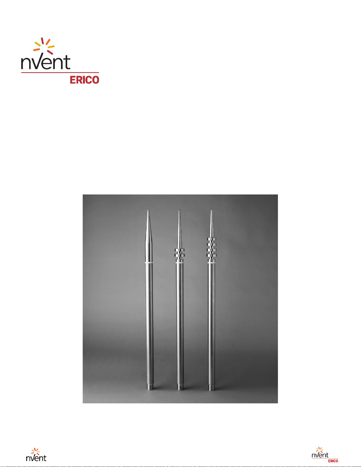
During thunderstorm conditions, when the lightning down leader is approaching ground level, an upward leader
may be created by any surface. In the case of a passive lightning rod, the upward leader propagates only after
a long period of charge reorganization. In the case of the ESE i-Series, the initiation time of an upward leader
is significantly reduced. The ESE i-Series generates controlled magnitude and frequency pulses at the tip of
the ESE terminal during high static fields prior to a lightning discharge. This enables creation of an upward
leader from the ESE air terminal that propagates toward the thundercloud downward leader.
PURCHASER ACKNOWLEDGES THAT LIGHTENING IS A NATURAL EVENT WITH STATISTICAL
VARIATION IN BEHAVIOR AND 100% PROTECTION IS NOT OFFERED AND CANNOT BE PROVIDED.
The design methods for the placement of nVent ERICO System 1000 ESE air terminals on structures are based
on the calculations using formulas published in the Standard NF C 17-102. The French standard NF C 17-102
is the guiding document for ESE lightning protection systems. The NF C 17-102 standard and this manual shall
be used as the main references for the System 1000 installation. Please note that the French Standard NF C
17-102 is used in other countries under different names of the local standard. Some examples include: Argentina
IRAM 2426, Spain UNE 21186, Macedonia MKS N.B4 810,Portugal NP 4426, Romania I-20, Slovakia STN 34
1391.
IN ALL CASES THE INSTALLER AND THE AUTHORITY HAVING JURISDICTION OVER THE SITE ARE
RESPONSIBLE FOR THE INSTALLATION OF THE ERICO SYSTEM 1000 ESE AS WELL AS ENSURING
THAT THE INSTALLATION COMPLIES TO THE LATEST NF C 17-102 AND IEC EN 62651-2 STANDARDS.
IMPROPER INSTALLATION, MISUSE, MISAPPLICATION OR OTHER FAILURE TO COMPLETELY FOLLOW
ERICO’S INSTRUCTIONS AND WARNINGS MAY CAUSE PRODUCT MALFUNCTION, PROPERTY DAMAGE,
SERIOUS BODILY INJURY AND DEATH. NVENT EXCLUDES ALL OTHER LIABILITY EXCEPT SUCH
LIABILITY THAT IS DIRECTLY ATTRIBUTABLE TO THE GROSS NEGLIGENCE OF NVENTS EMPLOYEES.
SHOULD NVENT BE FOUND LIABLE BY A COURT OF COMPETENT JURISDICTION ITS LIABILITY SHALL
IN NO EVENT EXCEED THE TOTAL PURCHASE PRICE PAID UNDER THE CONTRACT. NVENT SHALL IN
NO EVENT BE RESPONSIBLE FOR ANY LOSS OF BUSINESS OR PROFITS, DOWNTIME OR DELAY,
LABOR, REPAIR OR MATERIAL COSTS OR ANY SIMILAR OR DISSIMILAR CONSEQUENTIAL LOSS OR
DAMAGE INCURRED BY PURCHASER. ALL OTHER TERMS AND CONDITIONS FOR THIS PRODUCT ARE
AS SET OUT IN NVENT ERICOS QUOTATION DOCUMENTS AND TERMS AND CONDITIONS OF SALE.
Operation
The ESE air terminal contains a passive charging circuit that operates automatically. The air terminal becomes
active only during thunderstorms. It does not require external power or component replacement during normal
operation.
Warning: Do not attempt to install the nVent ERICO System 1000 during periods of lightning activity.
This Installation, Operation and Maintenance Manual assumes that in all cases, the System 1000 is designed
by nVent ERICO Engineering or other qualified representative with specific experience in Standard NF C 17-
102. It is understood that a design is formulated using data provided by the customer as to site layout and
measurements and in accordance with all relevant standards.
NVENT DISCLAIMS LIABILITY FOR LOSS OR DAMAGE THAT MAY ARISE DUE TO THE INSTALLATION
OF PRODUCTS WHERE ACTUAL SITE CONDITIONS VARY FROM THOSE PROVIDED TO NVENTIT IS
THE RESPONSIBILITY OF THE CUSTOMER TO ENSURE THAT THE INSTALLATION OF THE PRODUCTS
DOES NOT DEVIATE FROM THE DESIGN PROVIDED BY NVENT OR OTHER QUALIFIED

IP9032_A Page | 4 © 2022 nVent All Rights Reserved
REPRESENTATIVE. THIS MANUAL IS NOT INTENDED AND SHOULD NOT BE USED AS A DESIGN GUIDE.
ANY DESIGN OR STANDARD INFORMATION BELOW IS INTENDED FOR REFERENCE ONLY AS SITE
CONDITIONS WILL VARY.
For a successful installation, the system design shall assure that:
1. The grounding system’s configurations should be designed as a result of soil resistivity analysis. The
required grounding system resistance shall be less than 10 Ω.
2. Downconductors shall comply with IEC EN 62651-2 and the path to ground should be as short as
possible.
3. Downconductor shall be secured using three fixings, at minimum, per meter (approximately every one
foot).
4. The design practices are outlined in the Standard NF C 17-102 and determine air terminal placement,
mast height and protection level calculations.
5. It is essential to adhere to local standards and regulations for relevant local down conductor and
grounding requirements.

IP9032_A Page | 5 © 2022 nVent All Rights Reserved
nVent ERICO System 1000: NFC 17-102 Standard Principles
nVent ERICO System 1000 components are intended for use in ESE-type lightning protection systems that
comply with the NFC 17-102 standard.
“This standard is applicable to Early Streamer Emission lightning protection systems provided to protect facilities
and open areas against direct lightning impact. This ESE System shall be tested, selected and installed
according to the latest revision of the standard.”
Radius of protection: Standard formulas
According to NFC 17-102:2011, the standard protection radius (Rp) of the ESE i-Series is linked to ΔT (below),
the protection levels I, II, III or IV (as calculated in EN 62305-2) and the height (h) of the ESE i-Series above
the structure or feature to be protected (defined by NFC 17-102 as a minimum 2 m).
Where 2 m ≤ h ≤ 5 m, then Rp can be calculated from
Where h≥5 m, then Rp can be calculated from
Rp (h) in meters, is the protection radius at a given height h
hin meters is the height of the ESEAT tip over the horizontal plane through the furthest point of the object to
be protected
rin meters is: 20 m for protection level I
30 m for protection level II
45 m for protection level III
60 m for protection level IV
Δ(m) Δ = ΔT (µs) x 106
Field experience has proved that Δ is equal to the efficiency obtained during the ESEAT evaluation
tests
Figure 1

IP9032_A Page | 6 © 2022 nVent All Rights Reserved
Radius of protection:
LEVEL I
LEVEL II
LEVEL III
LEVEL IV
Rp for 99%, D = 20 m
Rp for 97%, D = 30 m
Rp for 91%, D = 45 m)
Rp for 84%, D = 60 m
h
(m)
SI25i
SI40i
SI45i
SI60i
SI25i
SI40i
SI45i
SI60i
SI25i
SI40i
SI45i
SI60i
SI25i
SI40i
SI45i
SI60i
2
17.0
23.2
25.3
31.4
19.6
26.2
28.3
34.6
23.0
30.0
32.2
38.8
25.9
33.4
35.8
42.7
3
25.5
34.9
37.9
47.1
29.4
39.2
42.4
51.9
34.5
45.0
48.4
58.2
38.9
50.1
53.7
64.0
4
33.9
46.5
50.6
62.9
39.2
52.3
56.6
69.2
46.0
60.0
64.5
77.7
51.8
66.8
71.6
85.3
5
42.4
58.1
63.2
78.6
49.0
65.4
70.7
86.5
57.4
75.0
80.6
97.1
64.8
83.5
89.4
106.7
10
43.9
59.2
64.3
79.4
51.3
67.2
72.4
87.8
60.8
77.6
83.0
99.1
68.9
86.7
92.5
109.2
15
44.7
59.8
64.8
79.9
53.0
68.4
73.5
88.8
63.4
79.6
84.9
100.7
72.3
89.4
95.0
111.3
20
45.0
60.0
65.0
80.0
54.1
69.3
74.4
89.5
65.5
81.3
86.5
102.0
75.1
91.8
97.2
113.2
30
43.8
59.1
64.2
79.3
55.0
70.0
75.0
90.0
68.4
83.7
88.8
104.0
79.6
95.5
100.7
116.3
40
40.2
56.5
61.8
77.4
54.0
69.2
74.3
89.4
69.8
84.9
89.9
104.9
82.7
98.0
103.1
118.4
50
33.3
51.8
57.5
74.1
51.1
67.0
72.2
87.7
69.8
84.8
89.8
104.9
84.4
99.5
104.5
119.6
60
20.1
44.5
51.0
69.1
45.9
63.1
68.6
84.8
68.3
83.6
88.7
103.9
85.0
100.0
105.0
120.0
Note: Values in meters. 5 m of the terminal is the referenced radius of protection.
The level of protection should be determined by IEC EN 62305-2 Risk Assessment
Table 1
Separation distance
The separation distance must be calculated using IEC EN 62305-3 in order to avoid a dangerous spark. It may
be necessary to add extra dowconductors or use an insulated downconductor.

IP9032_A Page | 7 © 2022 nVent All Rights Reserved
nVent ERICO System 1000 Installation
Safety Instructions:
1. All governing codes and regulations and those required by the job site must be observed. Always use
appropriate safety equipment such as eye protection, hard hat, fall protection harness and gloves as
appropriate to the application.
2. The System 1000 products are manufactured by nVent ERICO.
Local distributors should be the user’s first point of contact with supply, delivery, installation, limited
warranty and checking of the system for compliance with the manufacturer’s instructions.
Warning:
1. nVent ERICO products shall be installed and used only as indicated in nVent ERICO product instruction
sheets and this manual. Instruction sheets are available at www.nVent.com and from your nVent ERICO
customer service representative.
2. nVent ERICO products must never be used for a purpose other than the purpose for which they were
designed or in a manner that exceeds specified load ratings.
3. All instructions must be completely followed to ensure proper and safe installation and performance.
4. Improper installation, misuse, misapplication or other failure to completely follow ERICO’s instructions
and warnings may cause product malfunction, property damage, serious bodily injury and death.
Installation Configurations Recommended by nVent ERICO
1. nVent ERICO does not warranty the installation of the nVent ERICO System 1000, only the components.
2. Recommendations from nVent ERICO Engineering are listed in nVent ERICO Lightning Protection Mast
Wind Ratings manuals, one for North America and one for Worldwide use.
3. Mast installations that do not meet the installation prints included in the nVent ERICO Mast Wind Loading
Ratings manuals shall automatically void the product warranty.
4. Based on these guides, nVent ERICO Engineering can provide forces exerted on the brackets and guy
wires, by certain maximum wind speeds. These recommendations help the structural engineer to select
the proper hardware to support the installation.
5. nVent ERICO documented wind load ratings are available upon request. If the lower section of the mast
is conductive, it must be electrically bonded to the nearest conductive structural point.
Recommended Order of Installation
1. Complete installation of a grounding system.
2. Complete installation of downconductor(s).
3. Termination of the downconductor(s) to the grounding system.
4. Terminate the top of the downconductor(s) to the nVent ERICO Early Streamer Terminal.
5. Verify the ESE terminal and attach the terminal to the top of the mast.
6. Raise the mast into position and secure.
7. The nVent ERICO System 1000 must be at least two meters higher than any point or object on the
structure it is intended to protect.
8. The resistance of the lightning protection grounding system must be less than 10 ohms. This should be
measured without downconductor(s) connected and without interconnection to other grounding systems.

IP9032_A Page | 8 © 2022 nVent All Rights Reserved
ESE Air Terminals
nVent ERICO ESE air terminals are rated for ∆T 25µs, 40µs, 45µ and 60µs triggering time. The
function of the rings at the top of the terminals is to easily distinguish the rated efficiency. No ring
corresponds to ∆T 25µs, two rings to ∆T 40µs or 45µs and four rings to ∆T 60µs. Do not install
nVent ERICO ESE air terminals without checking the correct trigger rating based on the lightning
protection system design.
304L series
Part Number
Triggered
Advance, ∆T
Stainless
Steel Material
UL
certification
file
SI25i
25 µs
304L (EN
1.4306)
UL E507847
SI40i
40 µs
304L (EN
1.4306)
SI45i
45 µs
304L (EN
1.4306)
SI60i
60 µs
304L (EN
1.4306)
UL E507847
Note: UL (NF C17-102) OVHC.E507847 Table 2
316L series
Part Number
Triggered Advance, ∆T
Stainless Steel Material
SI60i316
60 µs
316L (EN 1.4404)
Table 3
316L RT series (for remote tester)
Part Number
Triggered
Advance,
∆T
Stainless
Steel
Material
Accessories
included
SI60i316RT
60 µs
316L (EN
1.4404)
Base connector
SI60I316RT-
KIT
60 µs
316L (EN
1.4404)
SIREMOTETESTER
Table 4

IP9032_A Page | 9 © 2022 nVent All Rights Reserved
Raising of Masts
Ensure that:
1. There are no overhead AC power lines.
2. There is nothing overhead that will obstruct the lift.
3. There is enough manpower available to conduct the lift safely.
4. There is only ONE person in control of the lift.
5. Everyone involved in the lift knows what has been planned and how the lift is to be performed.
6. The mast is securely footed and cannot move out of control during the lift.
7. Any guying has been properly secured at the mast anchor points.
8. The downconductor has been correctly terminated and the structure bonding cable has been attached to
the termination.
9. The downconductor cannot bedamaged atthe base ofthe mast while lifting; maintain a minimum bending
radius of 20 cm (8 in.).
10. The mast can be easily and safely secured at the base and guying points immediately after it has been
lifted into position.
11. Any extra rigging that is required for the lift is removed only after the mast is in place. It may be necessary
to use a gin pole arrangement to assist when lifting the mast, especially if the mast is over 5 m (20 feet)
in height or is being lifted from a sloped surface. A typical arrangement is shown in Figure 2. When using
a crane to lift the mast into position, ensure that:
a. The crane has enough weight and height capacity to perform the job safely.
b. There is nothing overhead that will obstruct the lift.
c. Any guying has been properly secured at the mast anchor points.
d. The nVent ERICO SI ESE air terminal is NOT used as a slinging point.
e. When slinging the mast, ensure that the slings or harnesses cannot foul or bend the mast and /
or the nVent ERICO ESE air terminal.
f. The downconductor cannot be damaged as a result of dragging over rough or sharp surfaces
during the lift.
When ready to raise the guyed mast, check the following:
1. Guys to the mast anchor points are properly secured.
2. Ensure the guys are not twisted, kinked or damaged in any way.
3. Ensure that each guy can be easily secured at the anchors when the mast has been raised.
4. Turnbuckles or rigging screws are recommended at the base anchor points of the guys to enable easy
vertical alignment of the mast and correct tensioning of the guys.
5. If using turnbuckles, ensure that they are wired securely with nichrome wire. Remember to always
consistently plan the lift before attempting it.
6. If the mast is to be raised by hand, ensure that it can be safely and easily managed manually. It is
recommended that a crane or other suitable equipment be used for anything over 6 m (20 feet) in height,
to minimize the possibility of the mast becoming bent or damaged.
7. It is very important to keep the mast straight during the lift.

IP9032_A Page | 10 © 2022 nVent All Rights Reserved
Figure 2
Figure 3

IP9032_A Page | 11 © 2022 nVent All Rights Reserved
Guying System
4 & 7 Meters and Custom (X length) Guy Kits
The guying material is a lightweight plastic coated fiberglass rope, which is non-conductive and must be used
with any section of FRP insulated mast material.
Guy Kit Specifications:
Part Numbers
Mast elevation
at 45º
Guy Diameter
Guy Length
Guy Tensile
Strength
GUYKIT4MGRIP
(701305)
4m (13 ½ft.)
4mm (5/32 in.)
6 m (20 ½ft.)
430 Kg (946 lb.)
GUYKIT7MGRIP
(701315)
7m (24 ½ft.)
5mm (3/16 in.)
10 m (34 ft.)
560 Kg (1232 lb.)
Table 5
If a customized guy kit has been supplied, then the actual guy length can be determined from the following:
Guy Length = 1.41 X, where X = the vertical height between the upper and lower guying points and the
assumed angle from horizontal is 45.
IMPORTANT RECOMMENDATIONS:
•When guying any mast, it is advised that the guying angle be no greater than 60° from horizontal.
•For SIM mast, we recommend to use GUYRING28. Guy wire thimbles will be secured to the guy ring.
•It is recommended that 8mm (5/16 in.) diameter stainless steel guying saddles are used for the base guy
anchors.
•If these are to beanchored toa concrete surface, then 6mm (¼ in.) diameter x40mm (1½ in.) depth(minimum)
masonry anchors or similar should be used.
•Each of the Guying Kits comes with six stainless steel thimbles to relieve stress on the guys at the anchor
points. These thimbles MUST be used when guying.
•When using shackles (5mm (3/16 in.) minimum), ensure that the shackle pins are secured with nichrome wire
to stop any chance of them loosening.
When securing the fiberglass guys, use the guying grips supplied in the Guying Kit, carefully following the
following instructions:
When securing guys, ensure that:
•Minimum of 3 grips are used per guy end.
•Grips spaced at a minimum of 30mm (1½ in.) on guys.
•Grips are correctly orientated - Grip base (saddle) on the ‘Live’ side of the guy and ‘U-bolt’ over the ‘Dead’
side or tail of the guy.
•No more than 60cN.m (5 lbf.in.) of torque is applied to the grips.
Thimble
Fibreglass "Dead" End
"Live" End
Saddle Base on "Live" Side
30mm (1.5in.)
Minimum Spacing
Between Saddles
30mm (1.5in.)
ECORE019.CDR
30/03/99
Figure 3

IP9032_A Page | 12 © 2022 nVent All Rights Reserved
Mast: Bases & Assemblies
The selection of the mast configuration is a mandatory requirement:
1. Elevate the terminal to the required height as determined by the design process, minimum height of 2 m
(6.6 feet) above the highest point or object on the structure.
2. The mast should be securely attached to the selected mounting point(s).
3. The mast should be guyed if applicable.
4. The hereafter assemblies are for common cases. For fastening the mast assembly to the structure it is
advisable that guidance from a local structural engineer that will follow the specific installation and local
regulations.
The ESE air terminal can be mounted with a cantilever or guyed mast assembly. nVent ERICO has instruction
prints detailing pre-configured mast assemblies that achieve terminal heights between 2m (6.6 feet) and 8m
(26.0 feet) above roof level. Wind loading calculations are available for each configuration upon request. Note:
It is the responsibility of the installation contractor to ensure the mast assembly is installed in a way that is
structurally sound. This requires a specific review of the installation and the site, which might include additional
considerations such as wind loading, ice loading, and/or vibration. It is the responsibility of the installer to have
the design reviewed by a registered professional engineer before being installed.
The below tables show installation print numbers for the desired mast series and terminal height. These detailed
installation sheets can be found at www.nVent.com. The pre-configured assemblies defined in these installation
prints are available for reference when designing and/or installing a lightning protection system. However, they
are not to be used in place of a completed lightning protection system design by qualified engineer.
Mast Bases
nVent ERICO supplies several types of bases to suit:
1. nVent ERICO brand of aluminum base with internal mast spigots.
2. Aluminum masts welded directly onto the required length of mast.
3. Stainless steel base with the mast spigots.

IP9032_A Page | 13 © 2022 nVent All Rights Reserved
PN
D
A
HS
WEIGHT
MBMAST3M
(502040)
MBMAST4M
(701340)
MBMAST5M
(701350)
MBMAST6M
(701360)
US all models
9.0” (228.6 mm)
Europe all
models
230.0 mm (9.05”)
US all models
7.0” (177.8 mm)
Europe all models
180.0 mm (7.09”)
US all models
0.5” (12.7 mm)
Europe all models
13 mm (0.51”)
8.6 Kg 19.0 lb
10.7 Kg 23.5 lb
13.6 Kg 30.0 lb
15.2 Kg 33.5 lb
SIMBASE2840
SIMBASE2840316
200 mm (7.87“)
170.0 mm (6.7”)
11.0 mm (0.43”)
1.23 Kg 2.71 lb
1.23 Kg 2.71 lb
ER2BASESS
ER3BASESS
9” (228.6 mm)
7” (177.8 mm)
1/2” (12.7 mm)
5.2 Kg 11.5 lb
5.6 Kg 12.4 lb
Table 6

IP9032_A Page | 14 © 2022 nVent All Rights Reserved
ER 304 Series Preconfigured Mast Assemblies
Example Mast Assembly: ER Cantilever 4m
Figure 4
ER Guyed Mast
Instruction IP
IP79116
IP79117
IP79118
IP79119
IP79120
IP79121
IP79122
Mast Height (m)
2m
3m
4m
5m
6m
7m
8m
INTCPTSIIER1
1
1
INTCPTSIIER2
1
1
1
1
1
ER11000SS
1
ER12000SS
1
ER22000SS
1
1
1
ER23000SS
1
1
1
1
ER32000SS
1
ER33000SS
1
1
1
1
ER2BASESS
1
1
ER3BASESS
1
1
1
1
1
GUYKIT4MGRIP
1
1
1
1
GUYKIT7MGRIP
1
1
1
1
CABTIESS
4
6
8
10
12
14
16

IP9032_A Page | 15 © 2022 nVent All Rights Reserved
ER Cantilever Mast
Instruction
IP79106
IP79107
IP79108
IP79109
Mast Height
3m
4m
6m
7m
H Above Roof
2m
3m
4m
5m
INTCPTSIIER1
1
INTCPTSIIER2
1
1
1
ER11000SS
1
ER22000SS
1
ER23000SS
1
1
1
ER32000SS
1
ER33000SS
1
1
CABTIESS
6
8
10
14
ALOF1GS
2
2
3
3
Table 7
SIM 304L Series Preconfigured Mast Assemblies
Example Mast Assembly: SIM Guyed & Cantilever
Figure 5

IP9032_A Page | 16 © 2022 nVent All Rights Reserved
Table 8
SIM 316L Series Preconfigured Mast Assemblies
SIM Guyed Mast in SS 316L
SIM Cantilever Mast in SS 316L
Instruction
IP852
8 p1
IP8528
p4
IP8528
p5
IP8528
p6
Instruction
IP8504
IP8504
p1
IP8504
p2
IP8504
p3
IP8504
p4
Mast Height (m)
2m
6m
7m
8m
Mast Height
2m
5m
5m
7m
8m
GUYKIT28
1
1
1
H above roof
2m
3m
4m
5m
6m
SIM28A2316
1
1
1
1
SIM28A2316
1
1
1
1
1
SIM33B2316
1
SIM33B2316
1
1
SIM33B3316
1
1
SIM33B3316
1
1
SIM40C2316
1
1
SIM40C2316
1
1
SIM40C3316
1
SIM40C3316
1
SIMBASE2840316
1
1
1
1
CABTIESS
6
9
12
14
17
GUYKIT4MGRIP
1
ALOF1GS
2
2
2
3
3
GUYKIT7MGRIP
1
1
TMCSS316
1
1
1
1
1
CABTIESS
7
18
21
24
TMCSS316
1
1
1
1
Table 9
SIM Guyed Mast in SS 304L
SIM Cantilever Mast in SS 304L
Instruction
IP8528
p1
IP8528
p2
IP8528
p3
IP8528
p4
IP8528
p5
IP8528
p6
Instruction
IP8504
IP8504
p1
IP8504
p2
IP8504
p3
IP8504
p4
Mast Height (m)
2m
4m
5m
6m
7m
8m
Mast
Height
2m
5m
5m
7m
8m
GUYKIT28
1
1
1
1
1
H above
roof
2m
3m
4m
5m
6m
SIM28A2
1
1
1
1
1
1
SIM28A2
1
1
1
1
1
SIM33B2
1
1
SIM33B2
1
1
SIM33B3
1
1
1
SIM33B3
1
1
SIM40C2
1
1
SIM40C2
1
1
SIM40C3
1
SIM40C3
1
SIMBASE2840
1
1
1
1
1
1
CABTIESS
6
9
12
14
17
GUYKIT4MGRIP
1
1
1
TMCSS
2
2
2
2
2
GUYKIT7MGRIP
1
1
ALOF1GS
2
2
2
3
3
CABTIESS
7
12
15
18
21
24
BASEADAPTER40
1
1
TMCSS
2
2
2
2
2
2

IP9032_A Page | 17 © 2022 nVent All Rights Reserved
FRP and Aluminum Series Preconfigured Mast Assemblies
ERICORE Guyed Mast in fiber
ERICORE Cantilever Mast in fiber
Instruction
IP8588
p1
IP8588
p2
IP8588
p3
IP8588
p4
Instruction
IP8590
p1
IP8590
p2
IP8590
p3
Mast Height (m)
5m
6m
7m
8m
Mast Height
5m
6m
8m
INTCPTSIIERICOR
1
1
1
1
H above roof
4m
5m
6m
INTCPTADBUTTSII
1
1
1
1
INTCPTSIIERICOR
1
1
1
FRP2MBLACK
1
1
1
1
INTCPTADBUTTSII
1
1
1
ERICORETRMOS
1
1
1
1
FRP2MBLACK
1
1
1
ERICORE/LTKIT/A
1
1
1
1
ERICORETRMOS
1
1
1
ILCOUPL
1
1
1
1
ERICORE/LTKIT/A
1
1
1
MBMAST3M
1
ILCOUPL
1
1
1
MBMAST4M
1
ALUM3M
1
MBMAST5M
1
ALUM4M
1
MBMAST6M
1
ALUM6M
1
GUYKIT4MGRIP
1
1
7000250S4
2
2
3
GUYKIT7MGRIP
1
1
CABTIESS
9
12
18
CABTIESS
9
12
15
18
CONSADE25
3 per meter of ERICORE
CONSADE25
3 per meter of ERICORE
CONSADFX
2 per CONSADE25
CONSADFX
2 per CONSADE25
Note: These mast configurations are only intended for use with nVent ERICO Ericore Conductor.
Table 10

IP9032_A Page | 18 © 2022 nVent All Rights Reserved
Free Standing Masts
nVent ERICO System 1000 can be adapted to free standing masts using guidance from a structural
engineer. Two examples are depicted in in Figures 6 and 7.
Figure 6
Figure 7

IP9032_A Page | 19 © 2022 nVent All Rights Reserved
ISOnV Preconfigured Mast Assemblies
Figure 8 Figure 9
ISOnV STAND
Mast in fiber
ISOnV
Cantilever
Mast in fiber
Instruction
IP852
9
IP853
1
IP853
5
IP853
0
IP853
4
IP853
6
Instruction
IP853
8
IP854
0
IP854
7
IP855
1
Terminal Height
4.3m
4.5m
5.9m
6.9m
7.1m
7.2m
Terminal
Height
4.1m
5.4m
5.4m
6.7m
ISONVESE
1
1
1
1
1
1
H above roof
3.5m
4.6m
4.5m
5.5m
ISOMASTASSY
1
1
1
1
1
1
ISONVESE
1
1
1
1
ISONVMASTA11
1
1
ISOMASTAS
SY
1
1
1
1
ISONVMASTA24
1
ISONVMAST
11
1
ISONVMASTA37
1
1
1
ISONVMAST
24
1
1
ISONVSTAND10
1
1
1
ISONVMAST
37
1
ISONVSTAND15
1
1
ISONVBKT15
2
2
3
3
ISONVSTAND25
1
LPTIESS25
4
8
8
12
ISONVBLOCKSE
T2
4
4
ISONVBLOCKSE
T4
4
4
ISONVBLOCKSE
T5
4
4
LPTIESS25
4
4
8
12
12
12
Table 10

IP9032_A Page | 20 © 2022 nVent All Rights Reserved
IMPORTANT:
•These tables are only indicative per one downconductor. For a correct design, the maximum
length of downconductor(s) must be calculated according to the separation distance. The system
can accept maximum of five downconductors per one terminal.
•ISOnV-type fixings and connections are not included and must meet nVent ERICO installations
recommendations. The mast configurations identified in the this section are compatible with all
nVent ERICO ESE air terminals.
•For isolated ISOnV Systems, please ask nVent ERICO for a design.
Downconductors
Below table shows the minimum requirements for the downconductors in a qualified LP system.
Commonly used downconductors include:
Tapes : tinned copper 30x2 and bare red copper 25x3
Insulated cables : cables ISOnV and ERICORE
Round copper, stranded : stranded smooth weave LPC126R or stranded copper
Round conductors, Ø8mm : solid copper or solid aluminum
For specific part numbers and attributes please refer to www.nvent.com.
Table of contents
Other nvent Protection Device manuals
Popular Protection Device manuals by other brands

SW Stahl PROFI Tools
SW Stahl PROFI Tools 11201L Instructions for use

Hubbell
Hubbell SPIKESHIELD HBL3P120B Installation instruction

Siemens
Siemens SIPROTEC 7RW80 manual

Engelbert Strauss
Engelbert Strauss 75.76.461 Instructions for use

GE Multilin
GE Multilin 745 Communications guide

ABB
ABB RET615 Product guide