Nyos OPUS 300 User manual

OPUS® 300
INSTRUCTIONS

2
VIDEO INSTRUCTIONS
AQUARIUM ASSEMBLY
VIDEO INSTRUCTIONS
EQUIPMENT INSTALLATION
VIDEO INSTRUCTIONS
STARTING THE TANK
VIDEO INSTRUCTIONS
ADDING LIVE STOCK

CONGRATULATIONS
Congratulations on your new Nyos®OPUS®Aquarium.
Before putting the product into operation, please read the
instructions carefully.
CONTENTS
SAFETY INSTRUCTIONS .............................................................. 4
ASSEMBLY.................................................................................. 6
FUNCTIONALITY AND EQUIPMENT REQUIRED............... ............. 17
STARTING THE TANK................................................................. 20
MAINTENANCE AND CARE......................................................... 23
EXPLODED DRAWING ................................................................ 26
PARTS LIST .............................................................................. 27
3
EN

SAFETY INSTRUCTIONS
4
(Fig. 1)

SAFETY INSTRUCTIONS
• Read the instructions carefully and fully prior to putting
the aquarium into operation and store it in a safe place.
• When using electrical equipment in or in close proximity
to the aquarium, observe the instructions of the respec-
tive manufacturer.
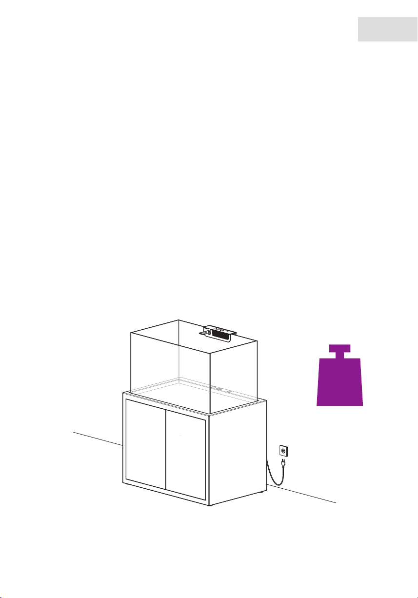
• With all electrical equipment, the cable must form a drip
loop so that no water is able to flow along the cable in
the direction of the socket. The drip loop must be positi-
oned above the respective water level (Fig. 1).
• This product is approved exclusively for use indoors and
only for aquarium applications.
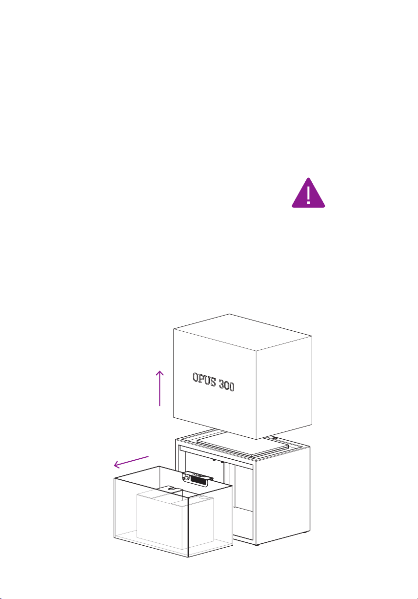
• Do not move the aquarium when filled, or attempt to lift it.
• Even when the aquarium is empty, never lift it by the
overflow box.
• Before putting hands in the water, disconnect all electri-
cal equipment from the power supply.
• This product is not intended for use by persons (including
children) with limited physical, sensory or mental capabi-
lities, unless they are supervised by a person responsible
for their safety, or have received instruction from such
a person on how to use the product. Children must be
supervised to ensure they do not play with the product.
5
EN

ASSEMBLY
VIDEO INSTRUCTIONS FOR
AQUARIUM ASSEMBLY
ASSEMBLY INSTRUCTIONS:
• At least 2 persons with sufficient physical strength are
required for assembly
• Tools required: Phillips screwdriver, scissors for silicone
cord
• Ready an underlay for intermediate placement of the
aquarium (e.g. carpet, towel)
• Do not use blades to remove the protective film or open
boxes, because these can scratch the aquarium, cabinet
or doors
STEP 1: SELECTION OF THE INSTALLATION SITE
• The floor on which the OPUS®300 is installed must be
level.
• The floor on which the OPUS®300 is installed must be
sufficiently load-bearing. The OPUS®300 has a base
surface of approx. 98x66 cm (38.6 x 26 in) and a weight
of approx. 500kg (1,100 lbs) when filled. In case of doubt,
consult a structural engineer in this regard.
• The aquarium should not be exposed to direct sunlight
because this can result in undesirable algae forming.
• The room should exhibit a normal room temperature of
approx. 20 – 24 °C (68-75°F).
• Do not install next to a radiator or an air conditioning
system.
6

ASSEMBLY
• Ensure sufficient and regular ventilation of the room.
• In order to guarantee sufficient space for cables and
ventilation of the cabinet, the rear side of the OPUS®300
should exhibit a distance of approx. 8 cm (3 in) from the
wall.
• For reasons of accessibility, the OPUS®300 should exhi-
bit a distance of approx. 60 cm (24 in) from neighbouring
walls or furniture on both the right and left side.
• Make sure the floor covering around the aquarium is
appropriately waterproof.
• Do not place any objects that could corrode due to salt
water, or that could be damaged by water, close to the
aquarium.
7
EN
approx.
500 kg
1,100 lbs
60 cm / 24 in
60 cm / 24 in
8 cm / 3 in

ASSEMBLY
STEP 2: UNPACKING
• The box can be lifted off and removed in one piece.
• Now prepare the underlay for intermediate placement of
the aquarium (e.g. carpet, sheet, hand towel).
• Carefullylifttheaquariumoutofthecabinetwiththe
helpofasecondperson.Whendoingso,makesurethe
aquariumremainsstraightandlevelwhenliftedout,to
avoiddamagetothecabinet.Set the aquarium down on
the prepared underlay and remove the protective film
from the aquarium.
• Remove the sump, refill tank, boxes and accessory parts
from the aquarium.
• Remove the doors on the cabinet and set them aside
initially.
8

ASSEMBLY
STEP 3: POSITIONING THE CABINET, AQUARIUM AND SUMP
• Align the cabinet horizontally at the final installation site
by unscrewing the feet.
• Carefullyplacetheaquariumonthecabinetwiththehelp
ofatleastonefurtherperson.Align the aquarium cent-
rally so that the gap between the cabinet and aquarium is
evenly sized on all sides. No underlay is required between
the aquarium and the cabinet.
• Unpack the sump and remove the cover panels from the
sump. Position the sump and black foam underlay cent-
rally in the cabinet. The Auto Top Off system (part no. 24)
must be on the front left side here.
9
EN

ASSEMBLY
STEP 4: PREPARING THE SUMP
• The transparent acrylic panel with the two PVC threaded
connections is fastened at the rear right on the sump
with the two transparent plastic screws (Fig. 2).
• Install the filter sock in the sump at the rear right (Fig. 3).
10
(Fig. 2)
(Fig. 3)

ASSEMBLY
STEP 5: INSTALLING THE PIPEWORK
• Perform a general check before installing the pipes to
ensure all O-rings are in the correct place.
• Start with the straight pipes (Fig. 4). Guide these in from
below through the holes in the cabinet, and then screw
tight in the overflow box (hand-tight, do not over-wind,
tool is not required). The pipe with the largest diameter
sits in the middle, the two narrower pipes are identical
and are fitted adjacent on the left and right.
• Connect the angled PVC pipes for the return pump,
overflow and emergency overflow with the threaded
connections. The angled PVC pipe with the black valve is
positioned in the centre (Fig. 5 – 7).
11
EN
(Fig. 4)
(Fig. 5)
(Fig. 6)
(Fig. 7)

ASSEMBLY
STEP 6: INSTALLING THE REFILL TANK
• The refill tank belongs in the left chamber of the sump
(return chamber). We recommend that the Auto Top Off
system be installed only after the aquarium has been
filled with seawater (see page 22, step 4).
• The cover panels can now be laid on the left and right
chamber of the sump.
12

ASSEMBLY
STEP 7: INSTALLING THE PUMP OUTLET
• An outlet port is located in the overflow box for the pump
outlet. This can be simply fitted on the pump outlet in the
aquarium.
13
EN

ASSEMBLY
STEP 8: FITTING THE DOORS
• First attach the hinges to the doors using the pre-drilled
holes and the screws provided (part number 29) (Fig. 8).
• Now attach the doors with hinges to the cabinet using
the pre-drilled holes and the screws provided (part num-
ber 29). A second person should hold the doors (Fig. 9).
• It is possible to align and straighten the doors using the
screws on the hinges.
14
(Fig. 8)
(Fig. 9)

ASSEMBLY
STEP 9: INSTALLING THE CABINET LIGHTING
• The LED lighting can be fastened in the cabinet at the
top right or top left (see sketch). Before fastening, check
that it switches on when the door is opened and off when
the door is closed.
15
EN

ASSEMBLY
STEP 10: FITTING THE SILICONE CORD
• The silicone cord provided is evenly pressed into the gap
between the aquarium and cabinet.
• Start on the rear side of the aquarium, roughly in the
centre beneath the overflow box.
• Fitthesiliconecordwithalittleexcessmaterialatthe
cornersoftheaquarium,sothatthecornersarecomple-
telyfilled.
• When the complete gap is filled all the way round, cut off
the surplus silicone cord.
16

FUNCTIONALITY AND EQUIPMENT REQUIRED
PIPEWORK, VALVE AND OVERFLOW BOX:
• The water from the display tank runs via the overflow box
into the main outflow pipe and then into the rear right
chamber of the sump.
• The second narrow outflow pipe in the overflow box is an
emergency outflow and is only used if the main outflow
pipe is blocked.
• The valve on the main outflow controls the water flow to
the sump and ensures that the outflow noise is kept to a
minimum.
SUMP:
1. A bubble trap is located in the right rear chamber of the
sump.
2. The water subsequently flows via a filter sock, which
filters dirt particles out of the water.
3. At the front right in the sump is a reserve chamber, in
which a media bag for active carbon, zeolite or similar
can be placed for example.
4. The middle chamber is the skimmer chamber with a
constant water level. It is also possible to install further
filters here, such as a media reactor (Nyos®TORQ®) for
example.
5. If necessary, it is also possible to install a filter sponge
as an additional bubble trap in the narrow chamber bet-
ween the skimmer chamber and return chamber.
17
EN

FUNCTIONALITY AND EQUIPMENT REQUIRED
6. In the chamber, far left, the water is fed back into the
display tank via the return pump. Because the water level
in the return chamber varies, compensation for the water
lost through evaporation takes place via the Auto Top Off
system.
18

FUNCTIONALITY AND EQUIPMENT REQUIRED
AUTO TOP OFF SYSTEM:
• Water that evaporates in all areas of the system can
only be detected through a drop in the water level in the
return chamber. The Auto Top Off system therefore only
adds water to the return chamber.
• Because sea salt does not evaporate, only use fresh wa-
ter (RODI Water) as compensation for water lost through
evaporation.
OVERVIEW OF FURTHER TECHNICAL COMPONENTS
REQUIRED:
There are many options for successfully operating a reef
aquarium. The following components are recommended on
the basis of our experience:
INFORMATION ON THE RETURN PUMP:
• The maximum pump capacity of the Nyos®OPUS®300
return pump must not exceed 2,000 l/h (530 gph). If this
is exceeded, the display tank could overflow!
Komponente Empfehlung für OPUS®300 Einsatzort
Skimmer Nyos®QUANTUM®120 Skimmer chamber of the sump
Return pump
Nyos®Viper 2.0 oder
EcoTech Marine Vectra S
Return chamber of the sump
Lighting 2 x Ecotech Marine XR 15W Display tank
Flow 2 x Ecotech Marine Vortech MP10wQD Display tank
Media reactor Nyos®TORQ®Skimmer chamber of the sump
19
EN

STARTING THE TANK
VIDEO INSTRUCTIONS FOR PUTTING
INTO OPERATION
STEP 1: REEF CONSTRUCTION AND SAND:
• We recommend to arrange the aqua scape whilst dry,
before filling the aquarium with seawater. This is sig-
nificantly easier than arranging the reef construction
underwater.
• When the aqua scape is finished, the sand can be added.
STEP 2: FILLING WITH SEAWATER
• Before filling for the first time, make sure all technical
components (skimmer, return pump, etc.) are installed in
compliance with the manufacturer’s safety instructions.
• The Auto Top Off system is only required once the aqua-
rium is in operation. We therefore recommend that the
refill tank be initially removed.
• Check the correct installation of the pipework once more.
First fully connect the valve by turning clockwise. Fill the
overflow box with a little water to test the leak-tightness
of the threaded connections on the overflow box.
• Fully open the valve before filling the main tank by tur-
ning it counterclockwise.
• Now start to fill the display tank with seawater.
20
Table of contents
Other Nyos Aquarium manuals